Page 25 of 44

80D-25
MR-413-X44-80D000$900_eng.mif
V1
LIGHTING
Fault finding - Fault Finding Chart80D
ALP 2
CONTINUED
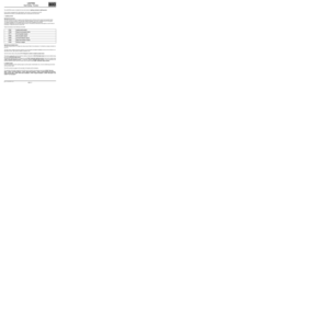
If + 12 V not found, check the rear fog lights relay:
Check the insulation, continuity and the absence of interference resistance on the following connections:
Right-hand rear fog light:
●Connection code 9P between components 172 and 1016.
Left-hand rear fog light:
●Connection code 9P between components 173 and 1016.
Check between the relay/fuse box and the fog light relay:
●Connection code BP16 between components 230 and 1016.
●Connection code 9P between components 230 and 1016.
If the connection or connections are faulty and there is a repair procedure (see Technical Note 6015A, Electrical
wiring repair, Wiring: Precautions for repair), repair the wiring, otherwise replace it.
Check between the horn and lights switch and the passenger compartment fuse and relay box:
●Connection code 9J between components 209 and 1016.
●Connection code BP59 between components 209 and 1016.
●Connection code BP11 between components 209 and 1016.
●Connection code MAN or MAM between components 209 and earth MAN or earth MAM (depending on the
driving layout, right- or left hand drive).
If the connection or connections are faulty and there is a repair procedure (see Technical Note 6015A, Electrical
wiring repair, Wiring: Precautions for repair), repair the wiring, otherwise replace it.
Check for + 12 V on connections BP59 and BP11 of component 209. Check for earth on connection MAN
(for right-hand drive vehicles) or MAM (for left-hand drive vehicles) of component 209.
If the connection or connections are faulty and there is a repair procedure (see Technical Note 6015A, Electrical
wiring repair, Wiring: Precautions for repair), repair the wiring, otherwise replace it.
If the supplies, earth and connections are correct, replace the horn and lights switch.
If the fault is still present, contact the Techline.
AFTER REPAIRCarry out a complete check with the diagnostic tool.
Page 26 of 44

80D-26
MR-413-X44-80D000$900_eng.mif
V1
LIGHTING
Fault finding - Fault Finding Chart80D
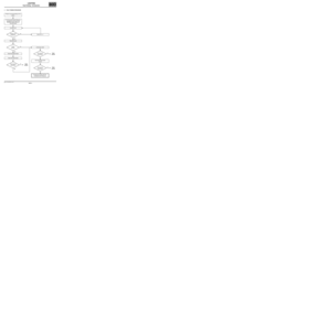
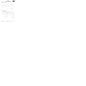
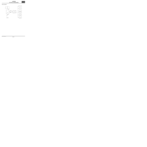
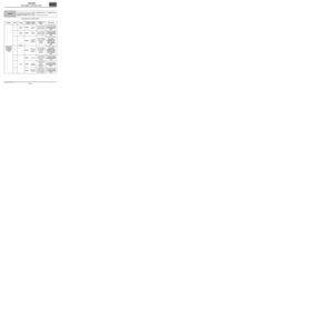
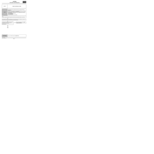
ALP 3 NO RIGHT hand DIRECTION INDICATOR
NOTESOnly refer to the customer complaints after performing a complete check using the
diagnostic tool.
Check the operation of status ET084 Right hand direction indicator request and
command AC023 Right hand direction indicator in the UCH. If there is a
malfunction on status ET084 "Right-hand indicator request" and command AC023
"Right-hand indicator", refer to the interpretation of status ET084 "Right-hand
indicator request" and of command AC023 "Right-hand indicator".
Check the condition of the bulbs and the cleanliness
of their contacts.
Are the bulbs and the contacts on the board
in good condition?
YES
Apply the fault procedure for DF012 Right-hand
direction indicator circuit (see 87B, Passenger
compartment connection unit, interpretation of
faults).
NOClean the contacts and replace any bulbs in
poor condition.
AFTER REPAIRCarry out a complete check with the diagnostic tool.
UCH_V44_ALP3
Page 27 of 44

80D-27
MR-413-X44-80D000$900_eng.mif
V1
LIGHTING
Fault finding - Fault Finding Chart80D
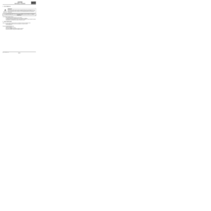
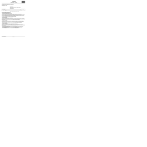
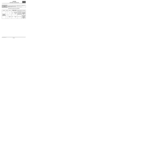
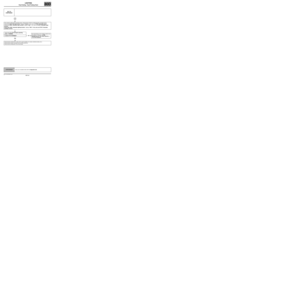
ALP 4 No left hand direction indicator
NOTESOnly refer to the customer complaints after performing a complete check using the
diagnostic tool.
Check, as a priority, the operation of status ET083 Left hand direction indicator and
command AC022 Left hand direction indicator in the UCH. If there is a malfunction
on status ET085 "Left-hand indicator request" and command AC022 "Left-hand
indicator", refer to the interpretation of status ET085 "Left-hand indicator request"
and of command AC022 "Left-hand indicator".
Check the condition of the bulbs and the cleanliness
of their contacts.
Are the bulbs and the contacts on the board
in good condition?
YES
Apply the procedure for processing fault DF013 Left-
hand direction indicator circuit (see 87B,
Passenger compartment connection unit,
interpretation of faults).
NOClean the contacts and replace any bulbs in
poor condition.
AFTER REPAIRCarry out a complete check with the diagnostic tool.
UCH_V44_ALP4
Page 28 of 44
:
If the vehicle lighting is not contro")
80D-28
MR-413-X44-80D000$900_eng.mif
V1
LIGHTING
Fault finding - Fault Finding Chart80D
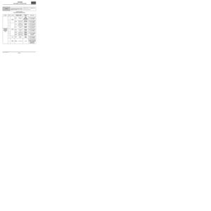
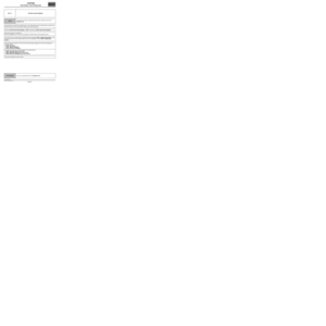
If the vehicle lighting is controlled by the UCH (with rain/light sensor):
If the vehicle lighting is not controlled by the UCH (no rain/light sensor):
ALP 5 No side lights
NOTESOnly check this customer complaint after performing a complete check with the
diagnostic tool.
Check, as a priority, the operation of status ET081 Lighting stalk position and
command AC055 Side lights in the UCH. If there is a malfunction on status ET081
"Lighting stalk position" and command AC055 "Side lights", refer to the
interpretation of status ET081 "Lighting stalk position" and of command AC055
"Side lights".
Carry out a multiplex network test. If the multiplex
network contains faults (see 88B, Multiplexing).
Check the condition of the bulbs and the cleanliness
of their contacts.
Are the bulbs and their contacts in good
condition?
YES
Replace the light concerned.
Check that fuses F13 (30 A), F42 (10 A) and F43 (10 A) are sound and correctly fitted in the passenger
compartment fuse and relay box.
Replace the fuse if necessary.
Check the condition and connection of the light connector concerned (bent, oxidised, broken tabs).
If the connection is faulty and there is a repair procedure (see Technical Note 6015A, Electrical wiring repair,
Wiring: Precautions for repair), repair the wiring, otherwise replace it.
Check the condition and connection of the horn and lights switch connector (tabs broken, bent, oxidised).
If the connection is faulty and there is a repair procedure (see Technical Note 6015A, Electrical wiring repair,
Wiring: Precautions for repair), repair the wiring, otherwise replace it.
NOClean the contacts and replace any bulbs in
poor condition.
AFTER REPAIRCarry out a complete check with the diagnostic tool.
UCH_V44_ALP5
Page 29 of 44
 on connection LPD of components 184 and")
80D-29
MR-413-X44-80D000$900_eng.mif
V1
LIGHTING
Fault finding - Fault Finding Chart80D
ALP 5
CONTINUED 1
Check for + 12 V (when there is a side lights request) on connection LPD of components 184 and 172 and
connection LPG on components 185 and 173. Check for an earth on connection MAR of component 184 and
connection MAS on component 185.
If the connection or connections are faulty and there is a repair procedure (see Technical Note 6015A, Electrical
wiring repair, Wiring: Precautions for repair), repair the wiring, otherwise replace it.
Side lights check:
Check the insulation, continuity and the absence of interference resistance on the following connections:
Right-hand front side light:
●Connection code LPD between components 184 and 1016.
●Connection code MAR between component 184 and earth MAR.
Left-hand front side light:
●Connection code LPG between components 185 and 1016.
●Connection code MAS between components 185 and earth MAS.
Rear right-hand side light:
●Connection code LPD between components 172 and 1016.
●Connection code MF between components 172 and earth MF.
Rear left-hand side light:
●Connection code LPG between components 173 and 1016.
●Connection code MG between components 173 and earth MG.
If the connection or connections are faulty and there is a repair procedure (see Technical Note 6015A, Electrical
wiring repair, Wiring: Precautions for repair), repair the wiring, otherwise replace it.
Check for + 12 V on connections BP59 and BP11 of component 209. Check for earth on connection MAN
(for right-hand drive vehicles) or MAM (for left-hand drive vehicles) of component 209.
If the connection or connections are faulty and there is a repair procedure (see Technical Note 6015A, Electrical
wiring repair, Wiring: Precautions for repair), repair the wiring, otherwise replace it.
AFTER REPAIRCarry out a complete check with the diagnostic tool.
Page 30 of 44
 and the passenger compartment fuse an")
80D-30
MR-413-X44-80D000$900_eng.mif
V1
LIGHTING
Fault finding - Fault Finding Chart80D
ALP 5
CONTINUED 2
Check between the horn and lights switch (component 209) and the passenger compartment fuse and
relay box (component 1016):
Check the insulation, continuity and the absence of interference resistance on the following connection:
●Connection code L between components 209 and 1016.
●Connection code BP59 between components 209 and 1016.
●Connection code MAN or MAM between components 209 and earth MAN or earth MAM (depending on the
driving layout, right- or left hand drive).
Check between the engine relay/fuse box (component 597) and the passenger compartment fuse and relay
box (component 1016):
●Connection code BP11 between components 597 and 1016.
●Connection code BP13 between components 597 and 1016.
If the connection or connections are faulty and there is a repair procedure (see Technical Note 6015A, Electrical
wiring repair, Wiring: Precautions for repair), repair the wiring, otherwise replace it.
If the supplies, earth and connections are correct, replace the horn and lights switch.
If the fault is still present, contact the Techline.
AFTER REPAIRCarry out a complete check with the diagnostic tool.
Page 31 of 44
:
If the vehicle lighting is not contro")
80D-31
MR-413-X44-80D000$900_eng.mif
V1
LIGHTING
Fault finding - Fault Finding Chart80D
If the vehicle lighting is controlled by the UCH (with rain/light sensor):
If the vehicle lighting is not controlled by the UCH (no rain/light sensor):
ALP 6 No dipped headlights
NOTESOnly check this customer complaint after performing a complete check with the
diagnostic tool.
Check, as a priority, the operation of status ET081 Lighting stalk position and
command AC054 Dipped headlights in the UCH. If there is a malfunction on status
ET081 "Lighting stalk position" and command AC054 "Dipped headlights", refer
to the interpretation of status ET081 "Lighting stalk position" and of command
AC054 "Dipped headlights".
Carry out a multiplex network test. If the multiplex
network contains faults (see 88B, Multiplexing).
Check the condition of the bulbs and the cleanliness
of their contacts.
Are the bulbs and their contacts in good
condition?
YES
Replace the light concerned.
Check that fuses F13 (30 A), F34 (15 A) and F35 (15 A) are sound and correctly fitted in the passenger
compartment fuse and relay box.
Replace the fuse if necessary.
Check the condition and connection of the light connector concerned (bent, oxidised, broken tabs).
If the connection is faulty and there is a repair procedure (see Technical Note 6015A, Electrical wiring repair,
Wiring: Precautions for repair), repair the wiring, otherwise replace it.
NOClean the contacts and replace any bulbs in
poor condition.
AFTER REPAIRCarry out a complete check with the diagnostic tool.
UCH_V44_ALP6
Page 32 of 44

80D-32
MR-413-X44-80D000$900_eng.mif
V1
LIGHTING
Fault finding - Fault Finding Chart80D
ALP 6
CONTINUED 1
Check the condition and connection of the horn and lights switch connector (tabs broken, bent, oxidised).
If the connection is faulty and there is a repair procedure (see Technical Note 6015A, Electrical wiring repair,
Wiring: Precautions for repair), repair the wiring, otherwise replace it.
Check for + 12 V (when there is a dipped headlights request) on connection CPD of component 226 and
connection CPG on the connection of component 227. Check for an earth on connection MAR of component 226
and on connection MAS on component 227. Check the supply to connection LPD on component 172 and the
supply to connection LPG on component 173.
Dipped headlights check:
Check the insulation, continuity and the absence of interference resistance on the following connections:
Right-hand front dipped headlight:
●Connection code CPD between components 226 and 1016.
●Connection code MAR between components 226 and earth MAR.
Left-hand front dipped headlight:
●Connection code CPG between components 227 and 1016.
●Connection code MAS between components 227 and earth MAS.
If the connection or connections are faulty and there is a repair procedure (see Technical Note 6015A, Electrical
wiring repair, Wiring: Precautions for repair), repair the wiring, otherwise replace it.
Check for + 12 V on connections BP59 and BP11 of component 209. Check for earth on the connection. Check
for earth on connection MAN (for right-hand drive vehicles) or MAM (for left-hand drive vehicles) of
component 209.
If the connection or connections are faulty and there is a repair procedure (see Technical Note 6015A, Electrical
wiring repair, Wiring: Precautions for repair), repair the wiring, otherwise replace it.
AFTER REPAIRCarry out a complete check with the diagnostic tool.