Page 215 of 269

13B-215V6 MR-413-X44-13B000$190.mif
DIESEL INJECTION
Fault finding – Tests13B
DCM 1.2 Injection
Program No.: 4D
Vdiag No.: 48, 4C, 50,
54, 58, 5C
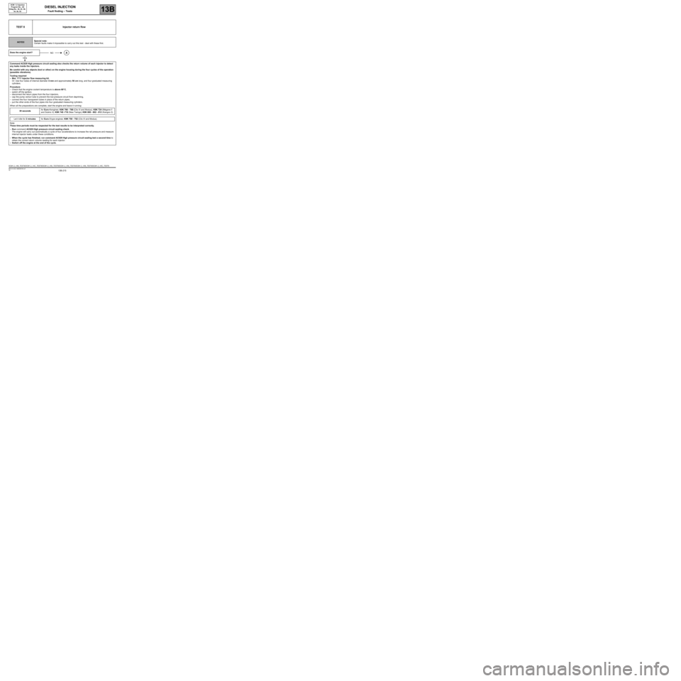
TEST 8 Injector return flow
NOTESSpecial note:
Certain faults make it impossible to carry out this test - deal with these first.
Does the engine start?
Command AC029 High pressure circuit sealing also checks the return volume of each injector to detect
any leaks inside the injectors.
Be careful with any objects (tool or other) on the engine housing during the four cycles of the operation
(possible vibrations).
Tooling required
–Mot. 1711 Injector flow measuring kit.
Or: Use four tubes of internal diameter 4 mm and approximately 50 cm long, and four graduated measuring
cylinders.
Procedure
–Check that the engine coolant temperature is above 60
°C,
–switch off the ignition,
–disconnect the return pipes from the four injectors,
–cap the pump venturi tube to prevent the low-pressure circuit from depriming,
–connect the four transparent tubes in place of the return pipes,
–put the other ends of the four pipes into four graduated measuring cylinders.
When all the preparations are complete, start the engine and leave it running:
30 secondsfor Euro 4 engines: K9K 766 - 768 (Clio III and Modus); K9K 724 (Mégane II
and Scénic II); K9K 740 -718 (New Twingo); K9K 800 - 802 - 812 (Kangoo 2).
Let it idle for 2 minutesfor Euro 3 type engines: K9K 750 - 752 (Clio III and Modus).
Note:
These time periods must be respected for the test results to be interpreted correctly.
–Run command AC029 High pressure circuit sealing check.
The engine will carry out automatically a cycle of four accelerations to increase the rail pressure and measure
internal injector leaks under these conditions.
–When the cycle has finished, run command AC029 High pressure circuit sealing test a second time to
obtain the correct return volume reading for each injector.
–Switch off the engine at the end of the cycle.
NOA
YES
DCM1.2_V48_TEST8/DCM1.2_V4C_TEST8/DCM1.2_V50_TEST8/DCM1.2_V54_TEST8/DCM1.2_V58_TEST8/DCM1.2_V5C_TEST8
Page 222 of 269

13B-222V6 MR-413-X44-13B000$190.mif
DIESEL INJECTION
Fault finding – Tests13B
DCM 1.2 Injection
Program No.: 4D
Vdiag No.: 48, 4C, 50,
54, 58, 5C
TEST 10
CONTINUED 3
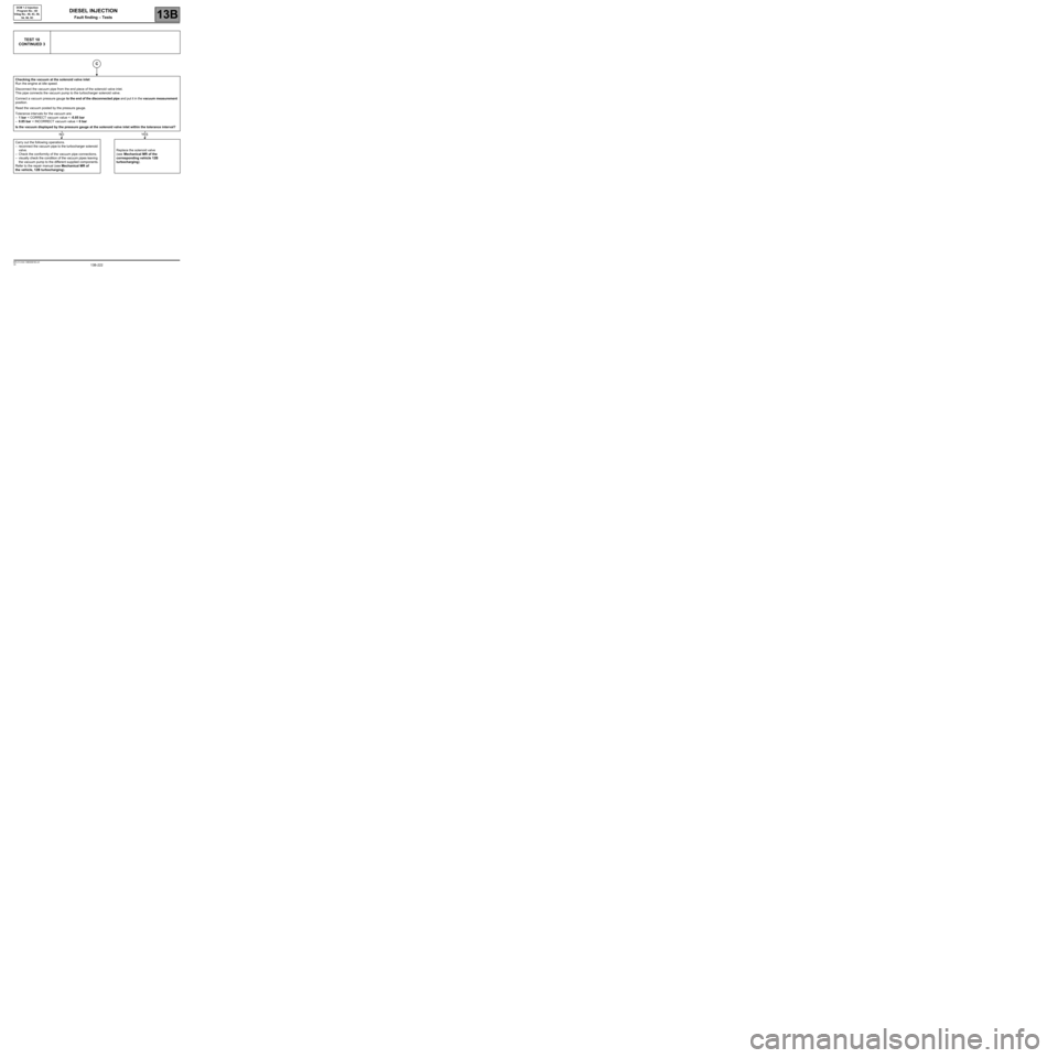
Checking the vacuum at the solenoid valve inlet
Run the engine at idle speed.
Disconnect the vacuum pipe from the end piece of the solenoid valve inlet.
This pipe connects the vacuum pump to the turbocharger solenoid valve.
Connect a vacuum pressure gauge to the end of the disconnected pipe and put it in the vacuum measurement
position.
Read the vacuum posted by the pressure gauge.
Tolerance intervals for the vacuum are:
–1 bar < CORRECT vacuum value < -0.85 bar
–0.85 bar < INCORRECT vacuum value < 0 bar
Is the vacuum displayed by the pressure gauge at the solenoid valve inlet within the tolerance interval?
Carry out the following operations.
–reconnect the vacuum pipe to the turbocharger solenoid
valve.
–Check the conformity of the vacuum pipe connections.
–visually check the condition of the vacuum pipes leaving
the vacuum pump to the different supplied components.
Refer to the repair manual (see Mechanical MR of
the vehicle, 12B turbocharging).Replace the solenoid valve
(see Mechanical MR of the
corresponding vehicle 12B
turbocharging).
C
NOYES
Page 225 of 269

13B-225V6 MR-413-X44-13B000$190.mif
DIESEL INJECTION
Fault finding – Tests13B
DCM 1.2 Injection
Program No.: 4D
Vdiag No.: 48, 4C, 50,
54, 58, 5C
TEST 12 Turbocharger
IMPORTANT
Perform these checks without removing the turbocharger and with the vehicle ignition switched off.
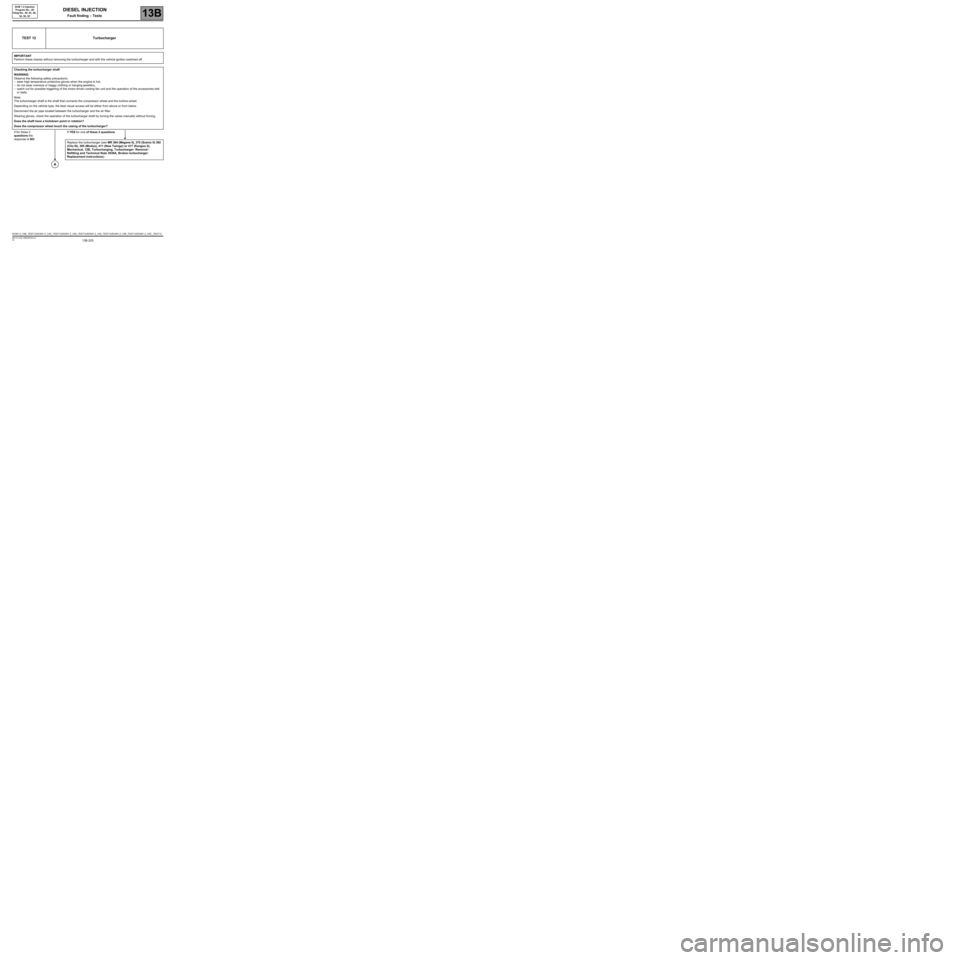
Checking the turbocharger shaft
WARNING
Observe the following safety precautions:
–wear high temperature protective gloves when the engine is hot,
–do not wear oversize or baggy clothing or hanging jewellery,
–watch out for possible triggering of the motor-driven cooling fan unit and the operation of the accessories belt
or belts.
Note:
The turbocharger shaft is the shaft that connects the compressor wheel and the turbine wheel.
Depending on the vehicle type, the best visual access will be either from above or from below.
Disconnect the air pipe located between the turbocharger and the air filter.
Wearing gloves, check the operation of the turbocharger shaft by turning the vanes manually without forcing.
Does the shaft have a kickdown point in rotation?
Does the compressor wheel touch the casing of the turbocharger?
If for these 2
questions the
response is NOIf YES for one of these 2 questions
Replace the turbocharger (see MR 364 (Mégane II), 370 (Scénic II) 392
(Clio III), 385 (Modus), 411 (New Twingo) or 417 (Kangoo II),
Mechanical, 12B, Turbocharging, Turbocharger: Removal -
Refitting and Technical Note 3938A, Broken turbocharger:
Replacement instructions).
A
DCM1.2_V48_TEST12/DCM1.2_V4C_TEST12/DCM1.2_V50_TEST12/DCM1.2_V54_TEST12/DCM1.2_V58_TEST12/DCM1.2_V5C_TEST12
Page 268 of 269

13B-268V6 MR-413-X44-13B000$210.mif
DIESEL INJECTION
Fault finding – Fault finding charts13B
DCM 1.2 Injection
Program No.: 4D
Vdiag No.: 48, 4C, 50,
54, 58, 5C
ALP18 Oil leaks from the turbocharger
NOTESBefore dealing with this customer complaint, check that there are no faults,
and the conformity (or otherwise) of the parameters and statuses using
the diagnostic tool.
If the customer complaint is not eliminated, perform the following checks.
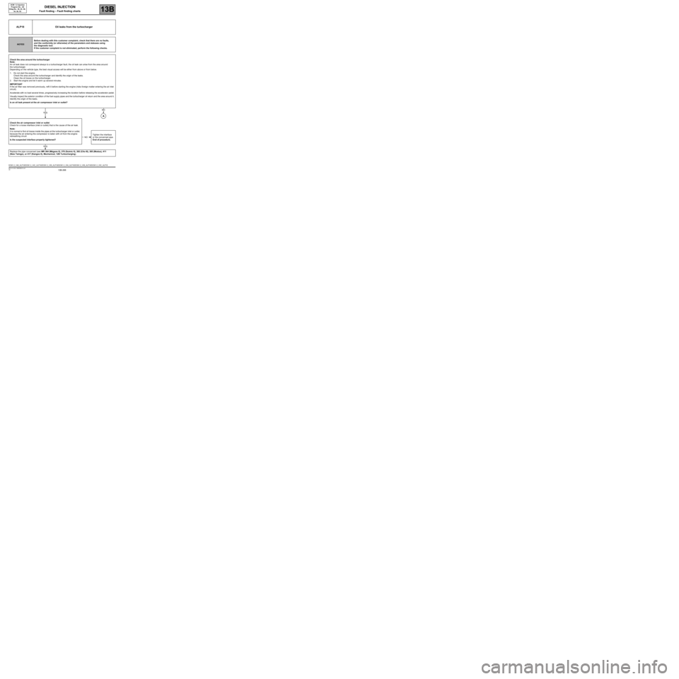
Check the area around the turbocharger
Note:
An oil leak does not correspond always to a turbocharger fault, the oil leak can arise from the area around
the turbocharger.
Depending on the vehicle type, the best visual access will be either from above or from below.
1. Do not start the engine.
Check the area around the turbocharger and identify the origin of the leaks.
Clean the oil traces on the turbocharger.
2. Start the engine and let it warm up several minutes.
IMPORTANT
If the air filter was removed previously, refit it before starting the engine (risks foreign matter entering the air inlet
circuit).
Accelerate with no load several times, progressively increasing the duration before releasing the accelerator pedal.
Visually inspect the exterior condition of the fuel supply pipes and the turbocharger oil return and the area around it.
Identify the origin of the leaks.
Is an oil leak present at the air compressor inlet or outlet?
Check the air compressor inlet or outlet
Check for a loose interface (inlet or outlet) that is the cause of the air leak.
Note:
It is normal to find oil traces inside the pipes at the turbocharger inlet or outlet,
because the air entering the compressor is laden with oil from the engine
rebreathing circuit.
Is the suspected interface properly tightened?Tighten the interface
or the concerned pipe.
End of procedure.
Replace the pipe concerned (see MR 364 (Mégane II), 370 (Scénic II), 392 (Clio III), 385 (Modus), 411
(New Twingo), or 417 (Kangoo II), Mechanical, 12B Turbocharging).
YES
NO
A
NO
YES
DCM1.2_V48_ALP18/DCM1.2_V4C_ALP18/DCM1.2_V50_ALP18/DCM1.2_V54_ALP18/DCM1.2_V58_ALP18/DCM1.2_V5C_ALP18