2009 RENAULT TWINGO oil type
[x] Cancel search: oil typePage 260 of 652

11A-143
TOP AND FRONT OF ENGINE
Camshaft seal, timing end: Removal - Refitting
K4M
11A
REFITTING
I - REFITTING PREPARATION OPERATION
aUse SURFACE CLEANER (see Vehicle: Parts
and consumables for the repair) (04B, Consuma-
bles - Products) to clean and degrease:
-the seal mating face of each camshaft,
-the cylinder head seal housings.
aparts always to be replaced: Camshaft seal on
timing end.
II - REFITTING OPERATION
a1 - Refitting the exhaust side seal
aPosition the protector fitted with a new seal (7) on
the camshaft (taking care not to touch the seal).
aScrew the stud (8) of the (Mot. 1632) onto the cam-
shaft. WARNING
Do not scrape the joint faces of the aluminium,
any damage caused to the joint face will result in
a risk of leaks.
WARNING
The joint faces must be clean, dr y and free from
grease (avoid finger marks).
18687
Note:
Always hold the camshaft seal with the protector
(5) when handling, as this type of camshaft seal
is very FRAGILE. Touching the camshaft seal (6)
is strictly forbidden in order to avoid any oil leaks
once the camshaft seal is fitted on the engine.
105531
126219
Page 298 of 652

12A-33
FUEL MIXTURE
Inlet distributor: Removal - Refitting
D4F, and 772
12A
REMOVAL
I - REMOVAL PREPARATION OPERATION
aRemove the air filter unit (see 12A, Fuel mixture,
Air filter unit: Removal - Refitting, page 12A-13) .
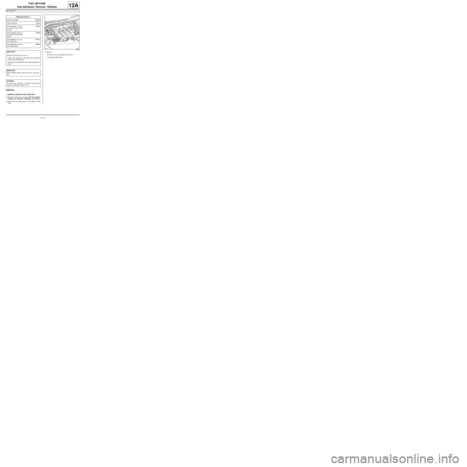
aUnclip the fuel supply pipe on the engine oil filler
neck.aRemove:
-the bolt (1) from the engine oil filler neck,
-the engine oil filler neck. Tightening torquesm
throttle valve bolts10 N.m
injector rail bolts7 N.m
inlet distributor nuts on
the rocker cover (initial
torque)8 N.m
inlet distributor bolts on
the cylinder head (initial
torque)3 N.m
inlet distributor nuts on
the rocker cover17 N.m
inlet distributor bolts on
the cylinder head9 N.m
IMPORTANT
During this oper ation, be sure to:
-refrain from smoking or bringing red hot objects
close to the working area,
-be careful of fuel splashes when disconnecting the
union.
IMPORTANT
Wear leaktight gloves (Nitrile type) for this opera-
tion.
WARNING
To avoid any corrosion or damage, protect the
areas on which fuel is likely to run.
120299
Page 302 of 652

12A-37
FUEL MIXTURE
Inlet distributor: Removal - Refitting
D4F, and 780 or 782
12A
REMOVAL
I - REMOVAL PREPARATION OPERATION
aRemove the throttle valve (see 12A, Fuel mixture,
Throttle valve: Removal - Refitting, page 12A-20)
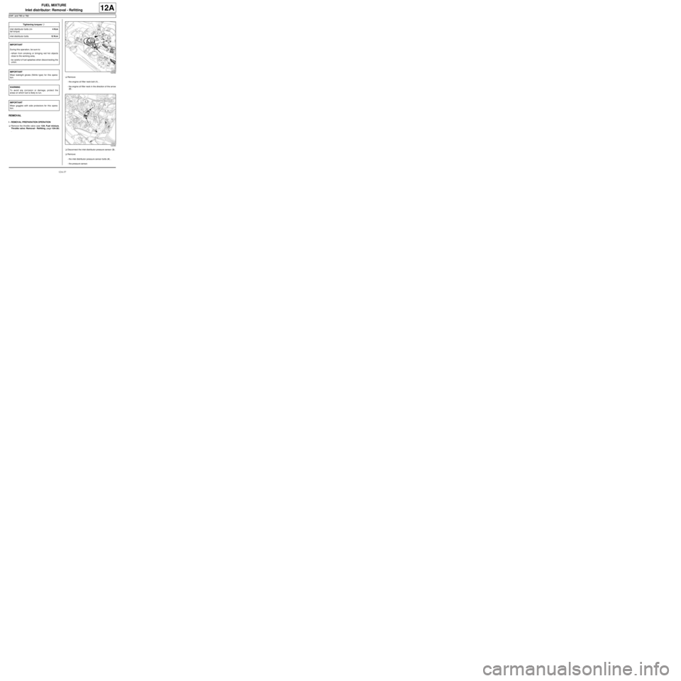
.aRemove:
-the engine oil filler neck bolt (1) ,
-the engine oil filler neck in the direction of the arrow
(2) .
aDisconnect the inlet distributor pressure sensor (3) .
aRemove:
-the inlet distributor pressure sensor bolts (4) ,
-the pressure sensor. Tightening torquesm
inlet distributor bolts (ini-
tial torque)4 N.m
inlet distributor bolts12 N.m
IMPORTANT
During this oper ation, be sure to:
-refrain from smoking or bringing red hot objects
close to the working area,
-be careful of fuel splashes when disconnecting the
union.
IMPORTANT
Wear leaktight gloves (Nitrile type) for this opera-
tion.
WARNING
To avoid any corrosion or damage, protect the
areas on which fuel is likely to run.
IMPORTANT
Wear goggles with side protectors for this opera-
tion.
122392
122393
Page 305 of 652

12A-40
FUEL MIXTURE
Inlet distributor: Removal - Refitting
K4M
12A
REMOVAL
I - REMOVAL PREPARATION OPERATION
aDisconnect the battery (see Battery: Removal - Re-
fitting) (80A, Battery).
aRemove:
-the windscreen wiper arms (see Windscreen wip-
er arm: Removal - Refitting) (85A, Wiping -
Washing),-the scuttle panel grille (see Scuttle panel grille:
Removal - Refitting) (56A, Exterior equipment),
-the scoop under the scuttle panel grille (see Scoop
under the scuttle panel grille: Removal - Refit-
ting) (56A, Exterior equipment),
-the dipstick.
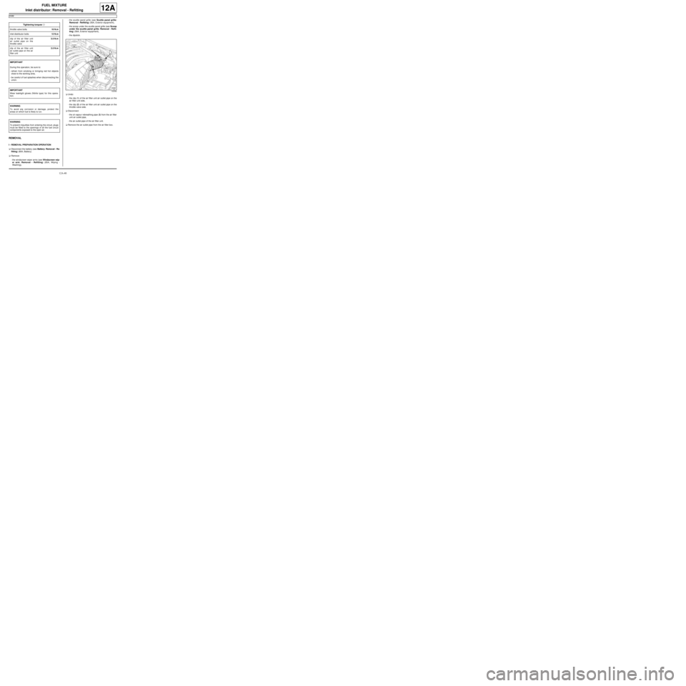
aUndo:
-the clip (1) of the air filter unit air outlet pipe on the
air filter unit side,
-the clip (2) of the air filter unit air outlet pipe on the
throttle valve side.
aDisconnect:
-the oil vapour rebreathing pipe (3) from the air filter
unit air outlet pipe,
-the air outlet pipe of the air filter unit.
aRemove the air outlet pipe from the air filter box. Tightening torquesm
throttle valve bolts10 N.m
inlet distributor bolts12 N.m
clip of the air filter unit
air outlet pipe on the
throttle valve3.5 N.m
clip of the air filter unit
air outlet pipe on the air
filter unit3.5 N.m
IMPORTANT
During this oper ation, be sure to:
-refrain from smoking or bringing red hot objects
close to the working area,
-be careful of fuel splashes when disconnecting the
union.
IMPORTANT
Wear leaktight gloves (Nitrile type) for this opera-
tion.
WARNING
To avoid any corrosion or damage, protect the
areas on which fuel is likely to run.
WARNING
To prevent impurities from entering the circuit, plugs
must be fitted to the openings of all the fuel circuit
components exposed to the open air.
132382
Page 328 of 652

12B-3
TURBOCHARGING
Turbocharging: Precautions for the repair
D4F or K9K
12B
One by one, clean the pipes removed with the parts
washer :
-brush as much of the inside of the pipe as possible
(only use brushes with plastic bristles),
-wash plenty of cleaning product from the cleaning sta-
tion through the pipe,
-allow the cleaned pipe to drain by standing it upright,
-ensure the cleaning product has drained out com-
pletely (check areas where liquid may be retained,
e.g. gaiters, resonators etc.).
Dry the pipes one by one using a compressed air spray
gun.
For pipes comprising several components:
-assemble the components, taking note of their correct
fitting position (10) .
Refit:
-the air pipe(between the air filter unit and the turbo-
charger) (A) ,
-the air pipe (B) (between the turbocharger and the in-
tercooler).
Refit the intercooler, if fitted to the vehicle (see 12B,
Turbocharging, Intercooler: Removal - Refitting,
page 12B-18) .V - LUBRICATION CIRCUIT**: INSTRUCTIONS
FOLLOWING MECHANICAL DAMAGE TO THE
TURBOCHARGER
Drain the engine oil (see 10A, Engine and cylinder
block assembly, Engine oil: Draining - Refilling,
page 10A-22) .
Replace the oil filter (see 10A, Engine and cylinder
block assembly, Oil filter: Removal - Refitting, page
10A-29) .
Only fill the engine with a suitable oil type (see Engine
oil: Specifications) (Technical Note 6013A, 04A, Lu-
bricants).
VI - GENERAL INSTRUCTIONS TO BE FOLLOWED
WHEN REMOVING A TURBOCHARGER
Always replace:
-the oil supply pipe:
•if the pipe is blocked, even partially (due to scale,
carbonised oil etc.),
•if the pipe is fitted with self-retaining seals.
-the oil return pipe:
•if the pipe is blocked, even partially (due to scale,
carbonised oil etc.),
•if the pipe is fitted with self-retaining seals.
-all seals that have been removed,
-all fittings that have been removed.
When starting the engine:
-do not accelerate,
-allow the engine to run for 1 minute,the time taken for
the oil circuit pressure to increase (until the oil pres-
sure warning light on the instrument panel goes out),
-accelerate several times at no load,
-check the air circuit and the oil circuit for leaks.
112771
Note:
(**) These instructions relating to the lubrication cir-
cuit must always be followed in all cases of
mechanical damage as listed above.
WARNING
Failure to observe the following procedure may lead
to destr uction of the turbocharger.
Page 352 of 652

13A-9
FUEL SUPPLY
Fuel pressure: Check
D4F or D7F
13A
CHECK
aI - PREPARATION OPERATION FOR CHECK
aEnsure you have a checking tool (Mot. 1311-01) and
a “T” union (Mot. 1311-08).
aRemove the oil filler neck.
II - TEST OPERATION
aDisconnect the petrol inlet pipe from the injector rail. Special tooling required
Mot. 1311-01Pressure gauges and petrol
pressure measur ing unions.
Mot. 1311-08Union for taking fuel pres-
sure measurements .
IMPORTANT
During this operation, be sure to:
-refrain from smoking or bringing red hot objects
close to the working area,
-be careful of fuel splashes when disconnecting
the union.
IMPORTANT
Wear goggles with side protectors for this opera-
tion.
IMPORTANT
Wear leaktight gloves (Nitrile type) for this opera-
tion.
WARNING
To avoid any corrosion or damage, protect the
areas on which fuel is likely to run.
116887
D4F
Page 357 of 652

13A-14
FUEL SUPPLY
Fuel flow: Check
D4F or D7F
13A
CHECK
a
I - PREPARATION OPERATION FOR CHECK
aRemove the oil filler neck.
aDisconnect the fuel supply union.aFit a “T” union to the fuel supply union (Mot. 1311-
08).
aFit a pipe which is long enough to drain the pump
into a container to the “T” outlet union. Special tooling required
Mot. 1311-08Union for taking fuel pres-
sure measurements .
Equipment required
graduated measuring cylinder
IMPORTANT
During this operation, be sure to:
-refrain from smoking or bringing red hot objects
close to the working area,
-be careful of fuel splashes when disconnecting
the union.
IMPORTANT
Wear goggles with side protectors for this opera-
tion.
IMPORTANT
Wear leaktight gloves (Nitrile type) for this opera-
tion.
WARNING
To avoid any corrosion or damage, protect the
areas on which fuel is likely to run.
D4F
D4F, and 772
121778
Page 363 of 652

13B-2
DIESEL INJECTION
Diesel injection: Precautions for the repair
K9K
13B
II - ADVICE TO BE FOLLOWED BEFORE ANY
OPERATION
1) Carry out the work in a clean working area and take
care to protect removed components from dust using
plastic bags which are hermetically-resealable, for ex-
ample.
2) Always order the following from the Parts Depart-
ment before carrying out work:
-a new set of blanking plugs, specific to the engine,
-enough lint-free cleaning cloths.
-one of the two cleaning products for fuel pipe
unions,
-the parts that are always to be replaced after each
removal operation, mentioned in the operational pro-
cedures specific to the vehicle (see related Workshop
Repair Manual).
3) Wear safety goggles fitted with side shields to pre-
vent the cleaning product from splashing the eyes.
4) Wear leaktight protective gloves (Nitrile type) to
avoid prolonged contact with the skin.
5) Before carrying out work on the injection system,
use plastic bags or clean rags, for example, to protect:
-the accessories and timing belts,
-the electrical accessories (starter, alternator, power-
assisted steering pump, sensors and electrical con-
nectors),
-the flywheel face.
III - INSTRUCTIONS TO BE FOLLOWED DURING
THE OPERATION
Wash your hands before and while carrying out the
work.
Replace leaktight protective gloves (Nitrile type) when
they are soiled or damaged.
All components removed from the injection system
must be stored in a hermetically sealed plastic bag
once they have been capped.
Reseal the bag hermetically, for example using adhe-
sive tape, even if the bag must be opened shortly after-
wards: ambient air can be a source of impurities.After opening the fuel circuit, the use of brushes, clean-
ing agents, air blow guns, rifle-type brushes or stan-
dard cloths is strictly prohibited: these items are likely
to allow impurities to enter the system.
When replacing a component with a new one or when
refitting it after storing it in a plastic bag, do not unpack
it until it is time to fit it on the vehicle.
IV - CLEANING
There are currently two procedures for cleaning the
fuel circuit before opening it in order to carry out work in
the workshop.
These procedures enable the fuel circuit to be cleaned
to prevent contamination from entering: they both have
the same end result and neither is preferred over the
other.
1 - Cleaning using injector cleaner
Clear the access to the unions that need opening, fol-
lowing the work procedures specific to the vehicle (see
the relevant Workshop Repair Manual).
Protect sections which are sensitive to fuel leaks.
Pour the injector cleaning agent into a container which
is free from impurities.
Dip a clean brush, which is not shedding bristles, into
the container of injector cleaning agent.
Clean the unions carefully using the brush and the in-
jector cleaning agent.
Blast the components that have been cleaned with
compressed air (tools, workbench, and also parts,
unions and around the injection system). Check that no
bristles from the brush have come away and that the
area is clean.
Wipe the sections that were cleaned with fresh clean-
ing cloths.
Open the circuit at the unions and immediately fit the
relevant blanking plugs. Note:
When using leather protective gloves, wear a pair of
leaktight protective gloves (Nitrile type) over the top.
IMPORTANT
Wear leaktight gloves (Nitrile type) for this opera-
tion.
IMPORTANT
Wear goggles with side protectors for this opera-
tion.