2009 RENAULT TWINGO check engine
[x] Cancel search: check enginePage 65 of 652

10A-59
ENGINE AND CYLINDER BLOCK ASSEMBLY
Oil pressure: Check
D4F or D7F or K9K
10A
I - RECOMMENDATIONS FOR REPAIR
a
II - PARTS AND CONSUMABLES FOR THE REPAIR
WORK
aParts which must be replaced:
-the sump plug sealing washer (in the event of an oil
change),
-oil filter (if removed).
aConsumable:
-Engine oil (see Engine oil: Specifications) (Tech-
nical Note 6013, 04A, Lubricants).
III - CHECK
aRemove the oil pressure sensor (see 10A, Engine
and cylinder block assembly, Oil pressure sen-
sor: Removal - Refitting, page 10A-45) .aCheck the correct operation of the oil pressure sen-
sor valve using the roll pin punch with a diameter of
2 mm and the multimeter. Special tooling required
Mot. 836-05Oil pressure gauge kit.
Mot. 1495-0122 mm socket for removal -
refitting of oxygen sensors.
Equipment required
roll pin punch
multimeter
1/2" long socket (12.7 mm square dr ive)
WARNING
Always check the oil level using the dipstick.
Do not exceed the maximum level on the dipstick
(could destroy the engine).
Correct the engine oil level if necessary before
delivering the vehicle to the customer.
Note:
When topping up the engine oil, always leave at
least 10 minutes before checking the level with a
dipstick.
It is essential to monitor the engine oil pressure
as the engine oil temperature rises (approxi-
mately 80˚C or the first time the engine cool-
ing fan is activated).
Page 66 of 652

10A-60
ENGINE AND CYLINDER BLOCK ASSEMBLY
Oil pressure: Check
D4F or D7F or K9K
10A
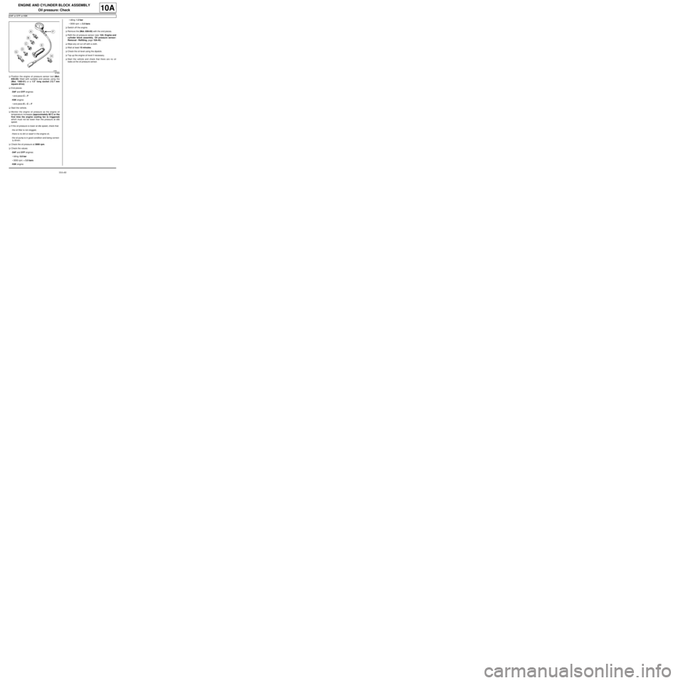
aPosition the engine oil pressure sensor tool (Mot.
836-05) fitted with suitable end pieces using the
(Mot. 1495-01) or a 1/2" long socket (12.7 mm
square drive).
aEnd pieces:
-D4F and D7F engines:
•end piece C + F
-K9K engine:
•end piece E + C + F
aStart the vehicle.
aMonitor the engine oil pressure as the engine oil
temperature increases (approximately 80˚C or the
first time the engine cooling fan is triggered)
which must not be lower than the pressure at idle
speed.
aIf the oil pressure is lower at idle speed, check that:
-the oil filter is not clogged,
-there is no dirt or swarf in the engine oil,
-the oil pump is in good condition and being correct-
ly driven.
aCheck the oil pressure at 3000 rpm.
aCheck the values:
-D4F and D7F engines:
•Idling: 0.8 bar
•3000 rpm: < 3.5 bars
-K9K engine•idling: 1.2 bar
•3000 rpm: < 3.5 bars
aSwitch off the engine.
aRemove the (Mot. 836-05) with the end pieces.
aRefit the oil pressure sensor (see 10A, Engine and
cylinder block assembly, Oil pressure sensor:
Removal - Refitting, page 10A-45) .
aWipe any oil run-off with a cloth.
aWait at least 10 minutes.
aCheck the oil level using the dipstick.
aTop up the engine oil level if necessary.
aStart the vehicle and check that there are no oil
leaks at the oil pressure sensor.
87363
Page 67 of 652

10A-61
ENGINE AND CYLINDER BLOCK ASSEMBLY
Oil pressure: Check
K4M
10A
Oil pressure tables:
End pieces to be used:
I - REMOVAL PREPARATION OPERATION
a
II - CHECK
aRemove the oil pressure sensor (see 10A, Engine
and cylinder block assembly, Oil pressure sen-
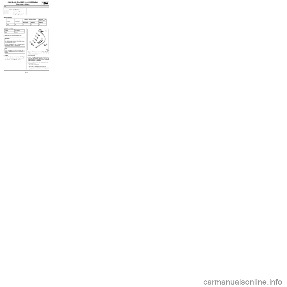
sor: Removal - Refitting, page 10A-45) .aIn place of the oil pressure sensor, fit the (Mot. 836-
05) with suitable adapters using the (Mot. 1495-01)
or a 22 mm long socket.
aStart the vehicle.
aMonitor the engine oil pressure as the oil tempera-
ture rises (approximately 80˚C or the first time the
engine cooling fan is activated); it should not be less
than the pressure at idle speed.
aIf the oil pressure is lower than the pressure at idle
speed, check that:
-the oil filter is not clogged,
-dirt or swarf is not present in the engine oil,
-the oil pump is in good condition and being correct-
ly driven. Special tooling required
Mot. 836-05Oil pressure gauge kit.
Mot. 1495-0122 mm socket for removal -
refitting of oxygen sensors.
Engine Engine suffixMinimum oil pressure (bar) Maximu m o i l
pressure (max)
Idling speed 4000 rpm 4000 rpm
K4M 8540.5 3.1 4.4
Engine End pieces
K4M E+C+F
WARNING
Always check the oil level using the dipstick.
Do not exceed the maximum level on the dipstick
(could destroy the engine).
Correct the engine oil level if necessary before
delivering the vehicle to the customer.
Note:
When topping up the engine oil, always leave at
least 10 minutes before checking the level with a
dipstick.
87363
Page 68 of 652

10A-62
ENGINE AND CYLINDER BLOCK ASSEMBLY
Oil pressure: Check
K4M
10A
aCheck the oil pressure in comparison with the values
given in the table above.
aSwitch off the engine.
aRemove the (Mot. 836-05) with the end pieces.
aRefit the oil pressure sensor (see 10A, Engine and
cylinder block assembly, Oil pressure sensor:
Removal - Refitting, page 10A-45) .
aWipe any oil run-off with a cloth.
aWait at least 10 minutes.
aCheck the oil level using the dipstick.
aTop up the oil level if necessary (see Engine oil:
Specifications) (Technical Note 6013A, 04A, Lubri-
cants).
aStart the vehicle and check that there are no oil
leaks at the oil pressure sensor.
Page 99 of 652

10A-93
ENGINE AND CYLINDER BLOCK ASSEMBLY
Engine - gearbox assembly: Removal - Refitting
K9K
10A
II - FINAL OPERATION
aRemove the.
aLubricate the seals using recommended air condi-
tioning oil to make fitting easier.
aRefit:
-the connecting pipes to the compressor,
-the connecting pipe union bolts on the compressor,
-the bolt for the connecting pipe mounting on the
compressor.
aConnect:
-the pressostat connector,
-the hose to the coolant pump inlet pipe using the
tool (Mot. 1448).
aFit:
-the hose clip on the coolant pump inlet pipe using
the tool (Mot. 1448),
-the earth on the front left-hand wing.
aRefit the earth nut on the front left-hand wing.
aClip:
-the engine compartment connection unit relay
plates,
-the fuse holders.
aRefit the fuses.
aConnect the preheating unit connector.
aRefit the earth nut on the front left-hand side mem-
ber.
aFit the engine compartment connection unit.
aRefit the engine compartment connection unit
mountings on the body.
aConnect the black connector.
aClip on the black connector.
aRefit:
-the engine compartment connection unit cover,
-a new clip on the battery mounting to hold the elec-
trical wiring.
aConnect the wiring connectors to the fan assembly.aClip the fan assembly wiring.
aRemove the blanking plugs.
aConnect the high pressure pump inlet pipe.
aClip on the fuel supply pipe.
aConnect the high pressure pump return pipe.
aClip on the fuel return pipe.
aRemove the blanking plugs on the clutch hydraulic
control and on the control pipe.
aConnect the clutch hydraulic control to the gearbox.
aClip:
-the clutch control hydraulic pipe on the gearbox,
-the gearbox controls on the cable sleeve stops,
-the gearbox controls on the gear selectors.
aConnect:
-the hoses to the heater radiator,
-the top hose to the water chamber.
aFit:
-the hose clips on the heater radiator using the tool
(Mot. 1448),
-the clip for the top hose on the water chamber us-
ing the tool (Mot. 1448).
aRefit:
-the front section of the intermediate pipe (see 19B,
Exhaust, Intermediate pipe: Removal - Refit-
ting, page 19B-28) ,
-the front right-hand wheel driveshaft (see Front
right-hand driveshaft: Removal - Refitting)
(29A, Driveshafts),
-the front left-hand wheel driveshaft (see Front left-
hand driveshaft: Removal - Refitting) (29A,
Driveshafts),
-the radiator mounting cross member (see Radiator
mounting cross member: Removal - Refitting)
(41A, Front lower structure),
-the front axle subframe (see Front axle subframe:
Removal - Refitting) (31A, Front axle compo-
nents),
-the engine tie-bar (see 19D, Engine mounting,
Lower engine tie-bar: Removal - Refitting, page
19D-18) . WARNING
To prevent any leaks, check that the seal and the
surface of the pipe are in good condition. The
seal and the surface must be clean and scratch
free.
Page 109 of 652

10A-103
ENGINE AND CYLINDER BLOCK ASSEMBLY
Engine - gearbox assembly: Removal - Refitting
K4M
10A
-the rubber pad mounting from the suspended en-
gine mounting on the gearbox.
aRemove the right-hand suspended engine mounting
(see 19D, Engine mounting, Right-hand sus-
pended engine mounting: Removal - Refitting,
page 19D-13) .
aLift the vehicle to remove the "engine and gearbox"
assembly.
REFITTING
I - REFITTING PREPARATION OPERATION
aFor standard engine replacement (see Standard re-
placement) (Technical Note 6023A, 10A, Engine
and peripherals).
II - REFITTING OPERATION
aPosition the "engine and gearbox" assembly in the
body.
aRefit the right-hand suspended engine mounting
(see 19D, Engine mounting, Right-hand sus-
pended engine mounting: Removal - Refitting,
page 19D-13) .
aRefit the rubber pad mounting from the suspended
engine mounting on the gearbox.
aTorque tighten the rubber pad mounting bolts for
the suspended engine mounting on the gearbox
(21 N.m).
aRefit the suspended engine mounting rubber pad.
aTorque tighten:
-the bolts of the suspended mounting rubber
pad (62 N.m),
-the suspended engine mounting shaft nut (62
N.m).
III - FINAL OPERATION
aRemove the.
aRemove the blanking plugs.
aConnect:
-the union of the brake servo vacuum pipe,
-the « compressor - condenser » connecting pipe,-the « compressor - intermediate pipe » connecting
pipe,
-the pressure sensor connector,
aConnect the hose on the coolant pump inlet pipe.
aFit the hose clip on the coolant pump inlet pipe using
the (Mot. 1448).
aRefit the earth nuts.
aClip:
-the relay plates on the engine compartment con-
nection unit,
-the fuse holders.
aConnect the fuses.
aRefit the engine compartment connection unit on the
body.
aConnect the connector to the engine compartment
connection unit.
aRefit the engine compartment connection unit cover.
aClip:
-the wiring on the engine cooling fan assembly,
-the cooling radiator top and bottom hoses on the
engine cooling fan assembly.
aConnect:
-the engine cooling fan assembly resistor connec-
tor,
-the engine cooling fan assembly connector.
aRemove the blanking plug from the fuel supply pipe
opening and the injector rail fuel opening.
aReconnect the fuel supply pipe.
aClip the fuel supply pipe in place.
aConnect:
-the fuel vapour absorber bleed solenoid valve con-
nector,
-the fuel vapour absorber bleed solenoid valve pipe.
aFit the gearbox control cables.
aClip the manual gearbox control cables onto:
-the gear selectors,
-the cable sleeve stops.
aRemove the blanking plug from the hydraulic clutch
control pipe opening and the opening of the clutch
thrust bearing.
aConnect the hydraulic clutch control pipe.
aClip the hydraulic clutch control pipe on the gearbox. Note:
Check no component obstructs the movement of
the body around the engine - gearbox assembly.
Page 118 of 652

11A-1
TOP AND FRONT OF ENGINE
Pressure at end of compression: Check
K4M
11A
CHECK
I - PREPARATION OPERATION FOR CHECK
aRemove:
-the coils (see 17A, Ignition, Coils: Removal - Re-
fitting, page 17A-1) ,
-the spark plugs (see 17A, Ignition, Plugs: Re-
moval - Refitting, page 17A-12) .
aDisconnect the injector wiring connector (1) .aConnect a petrol compression gauge (2) .
aPut the vehicle under the starting conditions by posi-
tioning the gear lever in neutral.
II - TEST OPERATION
aActivate the starter until the needle of the petrol
compression gauge stabilises.
aMeasure the cylinder compressions, cylinder by cyl-
inder.
aFully depress the accelerator pedal in order to open
the throttle valve during the compression measure-
ments.
III - FINAL OPERATION
aDisconnect the petrol compression gauge.
aConnect the injector wiring connector.
aRefit:
-the spark plugs (see 17A, Ignition, Plugs: Re-
moval - Refitting, page 17A-12) ,
-the coils (see 17A, Ignition, Coils: Removal - Re-
fitting, page 17A-1) . Equipment required
petrol compression gauge
132371
132338
Note:
It is necessar y to wait for at least 10 seconds
before starting the engine each time (the starter
will not run due to its ther mal protection).
Page 119 of 652

11A-2
TOP AND FRONT OF ENGINE
Pressure at end of compression: Check
D4F
11A
CHECK
I - PREPARATION OPERATION FOR CHECK
aRemove the plugs (see 17A, Ignition, Plugs: Re-
moval - Refitting, page 17A-12) .
aConnect a petrol compression gauge (1) .
aRun command with Diagnostic tool :
-RZ009: VEHICLE FUNCTION PROGRAMMING,
-VP036: FUEL SUPPLY INHIBITION.
aPut the vehicle under the starting conditions by posi-
tioning the gear lever in neutral.II - TEST OPERATION
aActivate the starter until the needle of the petrol
compression gauge stabilises.
aMeasure the cylinder compressions, cylinder by cyl-
inder.
aFully depress the accelerator pedal in order to open
the throttle valve during the compression measure-
ments.
III - FINAL OPERATION
aDisconnect the petrol compression gauge.
aRefit the plugs (see 17A, Ignition, Plugs: Removal
- Refitting, page 17A-12) .
aRun command VP037: "STOP INHIBIT FUEL SUP-
PLY" using the Diagnostic tool.
aStart the engine. Equipment required
petrol compression gauge
Diagnostic tool
Note:
Use a petrol compression gauge compatible with
the special tools.
The petrol compression gauge must be equipped
with a universal end piece (rubber), or a gaz 1/4
thread bolt.
132699
Note:
It is necessar y to wait for at least 10 seconds
before starting the engine each time (the starter
will not run due to its ther mal protection).
Note:
If the engine does not start, run command
VP037: STOP FUEL SUPPLY INHIBITION using
the Diagnostic tool or switch off the ignition and
wait 1 min before starting the engine again.