2009 RENAULT TWINGO air filter
[x] Cancel search: air filterPage 43 of 652
10A-37
ENGINE AND CYLINDER BLOCK ASSEMBLY
Conrod bearing shell: Removal - Refitting
K9K
10A
REMOVAL
I - REMOVAL PREPARATION OPERATION
aPosition the vehicle on a two-post lift (see Vehicle:
Towing and lifting) (02A, Lifting equipment).
aRemove the engine undertray.
aDrain the oil from the engine (see 10A, Engine and
cylinder block assembly, Engine oil: Draining -
Refilling, page 10A-22) .
aRemove the oil filter (see 10A, Engine and cylinder
block assembly, Oil filter: Removal - Refitting,
page 10A-29) .
aRemove the lower engine tie-bar (see 19D, Engine
mounting, Lower engine tie-bar: Removal - Refit-
ting, page 19D-18) .
aStrap the radiator to the vehicle using safety
strap(s).
aRemove the front axle subframe (see Front axle
subframe: Removal - Refitting) (31A, Front axle
components).
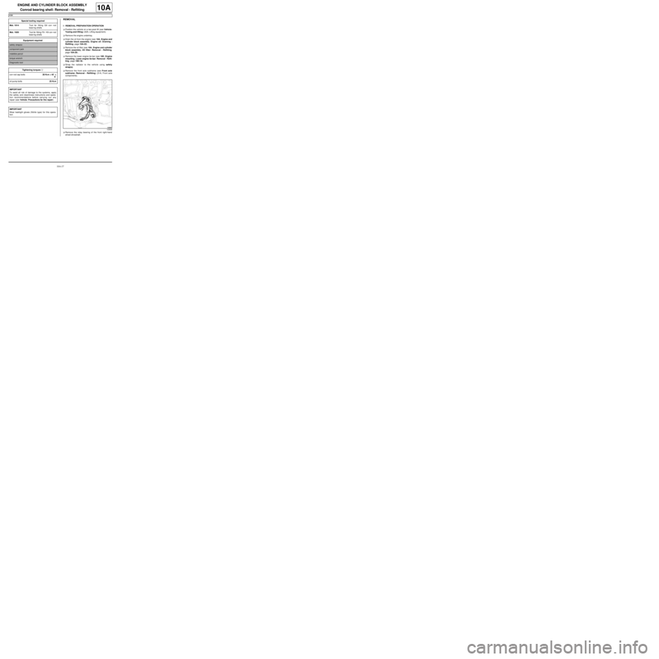
aRemove the relay bearing of the front right-hand
wheel driveshaft. Special tooling required
Mot. 1914Tool for fitting G9 con rod
bear ing shells
Mot. 1920Tool for fitting F9 / K9 con rod
bear ing shells
Equipment required
safety strap(s)
component jack
indelible pencil
torque wrench
Diagnostic tool
Tightening torquesm
con rod cap bolts20 N.m + 45˚ ±± ± ±
6˚
oil pump bolts25 N.m
IMPORTANT
To avoid all risk of damage to the systems, apply
the safety and cleanliness instructions and opera-
tion recommendations before carrying out any
repair (see Vehicle: Precautions for the repair) .
IMPORTANT
Wear leaktight gloves (Nitrile type) for this opera-
tion.
123838
Page 49 of 652
10A-43
ENGINE AND CYLINDER BLOCK ASSEMBLY
Conrod bearing shell: Removal - Refitting
K9K
10A
II - REMOVAL - REFITTING OPERATIONS FOR THE
CON ROD BEARING SHELLS ON CYLINDERS
NO.3, 1 AND 4
aPerform the same removal - refitting operations as
for the con rod bearing shells on cylinder no. 2.
III - FINAL OPERATION
aparts always to be replaced: engine oil sump
seal
parts always to be replaced: Oil filter
parts always to be replaced: Drain plug seal on
engine oil sump
aUse a wooden spatula or an ABRASIVE PAD to
clean the joint face of the cylinder block and engine
oil sump.
aRefit the oil pump.
aFit without tightening the oil pump bolts, while keep-
ing a clearance of 3 mm to 5 mm.
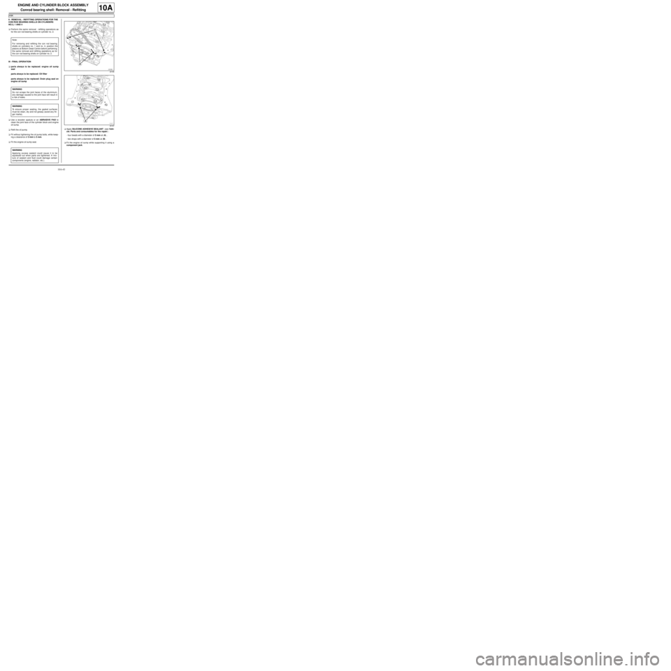
aFit the engine oil sump seal.aApply SILICONE ADHESIVE SEALANT (see Vehi-
cle: Parts and consumables for the repair) :
-four beads with a diameter of 5 mm at (A) ,
-two drops with a diameter of 5 mm at (B) .
aFit the engine oil sump while supporting it using a
component jack. Note:
For removing and refitting the con rod bearing
shells on cylinders no. 1 and no. 4, position the
pistons at Bottom Dead Centre before performing
the same removal and refitting operations as for
the con rod bearing shells on cylinder no. 2.
WARNING
Do not scrape the joint faces of the aluminium,
any damage caused to the joint face will result in
a risk of leaks.
WARNING
To ensure proper sealing, the gasket surfaces
must be clean, dry and not greasy (avoid any fin-
ger marks).
WARNING
Applying excess sealant could cause it to be
squeezed out when parts are tightened. A mix-
ture of sealant and fluid could damage certain
components (engine, radiator, etc.).
20166
20167
Page 53 of 652
10A-47
ENGINE AND CYLINDER BLOCK ASSEMBLY
Oil pressure sensor: Removal - Refitting
D4F, and 780 or 782
10A
REMOVAL
I - REMOVAL PREPARATION OPERATION
aPosition the vehicle on a two-post lift (see Vehicle:
Towing and lifting) (02A, Lifting equipment).
aRemove the air filter unit (see 12A, Fuel mixture,
Air filter unit: Removal - Refitting, page 12A-13) .
aUnclip the upstream oxygen sensor wiring harness
from the turbocharger heat shield.
II - OPERATION FOR REMOVAL OF PART
CONCERNED
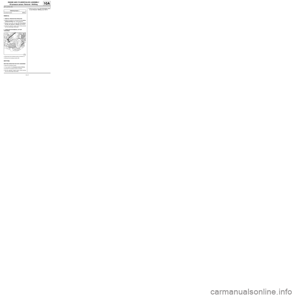
aDisconnect the oil pressure sensor connector (1) .
aRemove the oil pressure sensor (2) .
REFITTING
REFITTING OPERATION FOR PART CONCERNED
aRefit the oil pressure sensor.
aTorque tighten the oil pressure sensor (35 N.m).
aConnect the oil pressure sensor connector.
aClip the upstream oxygen sensor wiring harness
onto the turbocharger heat shield.aRefit the air filter unit (see 12A, Fuel mixture, Air fil-
ter unit: Removal - Refitting, page 12A-13) .
Tightening torquesm
oil pressure sensor35 N.m
121725
Page 65 of 652
10A-59
ENGINE AND CYLINDER BLOCK ASSEMBLY
Oil pressure: Check
D4F or D7F or K9K
10A
I - RECOMMENDATIONS FOR REPAIR
a
II - PARTS AND CONSUMABLES FOR THE REPAIR
WORK
aParts which must be replaced:
-the sump plug sealing washer (in the event of an oil
change),
-oil filter (if removed).
aConsumable:
-Engine oil (see Engine oil: Specifications) (Tech-
nical Note 6013, 04A, Lubricants).
III - CHECK
aRemove the oil pressure sensor (see 10A, Engine
and cylinder block assembly, Oil pressure sen-
sor: Removal - Refitting, page 10A-45) .aCheck the correct operation of the oil pressure sen-
sor valve using the roll pin punch with a diameter of
2 mm and the multimeter. Special tooling required
Mot. 836-05Oil pressure gauge kit.
Mot. 1495-0122 mm socket for removal -
refitting of oxygen sensors.
Equipment required
roll pin punch
multimeter
1/2" long socket (12.7 mm square dr ive)
WARNING
Always check the oil level using the dipstick.
Do not exceed the maximum level on the dipstick
(could destroy the engine).
Correct the engine oil level if necessary before
delivering the vehicle to the customer.
Note:
When topping up the engine oil, always leave at
least 10 minutes before checking the level with a
dipstick.
It is essential to monitor the engine oil pressure
as the engine oil temperature rises (approxi-
mately 80˚C or the first time the engine cool-
ing fan is activated).
Page 82 of 652

10A-76
ENGINE AND CYLINDER BLOCK ASSEMBLY
Engine - gearbox assembly: Removal - Refitting
D4F or D7F
10A
aRemove the bolt (4) from the expansion bottle.
aMove the expansion bottle aside following the ar-
rows (5) and (6) .
aRemove:
-the air filter box air inlet pipe from the cross mem-
ber,
-the air filter unit air inlet pipe,
-the cooling radiator upper bolts. JH3
120514
D4F or D7F, and 772
Page 83 of 652
10A-77
ENGINE AND CYLINDER BLOCK ASSEMBLY
Engine - gearbox assembly: Removal - Refitting
D4F or D7F
10A
a
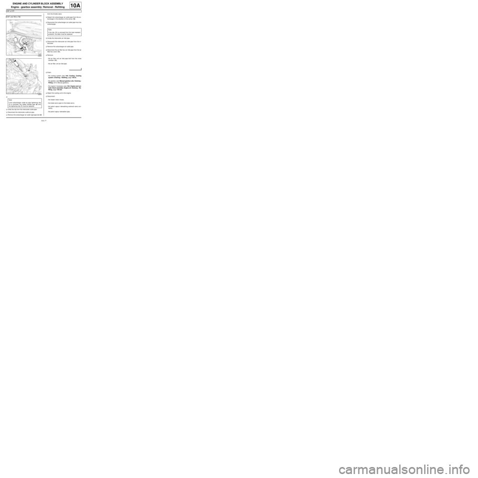
aUndo the clip from the intercooler outlet pipe.
aDisconnect the intercooler outlet air pipe.
aRemove the turbocharger air outlet rigid pipe bolt (9)from the throttle valve.
aDetach the turbocharger air outlet pipe from the tur-
bocharger in the direction of the arrow (10) .
aDisconnect the turbocharger air outlet pipe from the
turbocharger.
aUnclip the intercooler air inlet pipe.
aDisconnect the intercooler air inlet pipe from the in-
tercooler.
aRemove the turbocharger air outlet pipe.
aDisconnect the air filter box air inlet pipe from the air
filter box cover (12) .
aRemove:
-the air filter unit air inlet pipe bolt from the cross
member (13) ,
-the air filter unit air inlet pipe.
aDrain:
-the cooling system (see 19A, Cooling, Cooling
system: Draining - Refilling, page 19A-9) ,
-the gearbox (see Manual gearbox oils: Draining -
Filling) (21A, Manual gearbox),
-the engine if necessary (see 10A, Engine and cyl-
inder block assembly, Engine oil: Draining - Re-
filling, page 10A-22) .
aAttach the cooling unit to the engine.
aDisconnect:
-the heater matrix hoses,
-the brake servo pipe on the brake servo,
-the petrol vapour rebreathing solenoid valve con-
nector,
-the petrol vapour rebreather pipe. D4F, and 780 or 782
122833
122673
Note:
If the turbocharger outlet air pipe tightening clip
(7) is removed, the rubber flexible pipe (8) and
the tightening clip (7) must be replaced.
Note:
If the clip (11) is removed from the heat resistant
protector, the latter must be replaced.
Page 90 of 652
10A-84
ENGINE AND CYLINDER BLOCK ASSEMBLY
Engine - gearbox assembly: Removal - Refitting
D4F or D7F
10A
aRefit:
-the air conditioning pipe bolt on the dehydrator res-
ervoir,
-the air conditioning pipe bolts on the compressor.
aTighten:
-the air conditioning pipe bolts on the dehydrator
reservoir,
-the air conditioning pipe bolts on the compressor.
aFill the refrigerant circuit (see Refrigerant circuit:
Draining - Filling) (62A, Air conditioning).
aConnect:
-the petrol vapour rebreathing solenoid valve con-
nector,
-the brake servo pipe on the brake servo,
-the heater matrix hoses.
aFit the cooling unit.
aRefill:
-the engine oil, if necessary (see 10A, Engine and
cylinder block assembly, Engine oil: Draining -
Refilling, page 10A-22) ,
-the gearbox oil (see Manual gearbox oils: Drain-
ing - Filling) ,
-and bleed the cooling system (see 19A, Cooling,
Cooling system: Draining - Refilling, page 19A-
9) .
aRefit:
-the air filter unit air inlet pipe,
-the air filter unit air inlet pipe bolt on the cross
member.
aConnect the air filter box air inlet pipe on the air filter
box cover.
aRefit the turbocharger outlet air pipe.
aPush the intercooler air inlet pipe clip.
aConnect the intercooler air inlet pipe on the inter-
cooler.aPush the turbocharger outlet air pipe clip, following
the direction shown by the arrow (23) .
aConnect the turbocharger air outlet pipe onto the tur-
bocharger.
aRefit the turbocharger outlet rigid air pipe bolt on the
throttle valve.
aConnect the intercooler air outlet pipe to the inter-
cooler.
aTighten the intercooler air outlet pipe clip.
aRefit:
-the cooling radiator upper bolts.
-the air filter unit air inlet pipe,
-the air filter box air inlet pipe on the cross member,
aPosition the expansion bottle.
aRefit the expansion bottle bolt.
aClip the bonnet opening release cable on to the cool-
ing fan assembly.
aPosition the earth straps.
aRefit the earth strap nuts on the front right-hand side
member. D4F, and 780 or 782
122666
D4F or D7F, and 772
Page 92 of 652
10A-86
ENGINE AND CYLINDER BLOCK ASSEMBLY
Engine - gearbox assembly: Removal - Refitting
K9K
10A
REMOVAL
I - REMOVAL PREPARATION OPERATION
aPosition the vehicle on a two-post lift (see Vehicle:
Towing and lifting) (02A, Lifting equipment).
aRemove the battery (see ) (80A, Battery).
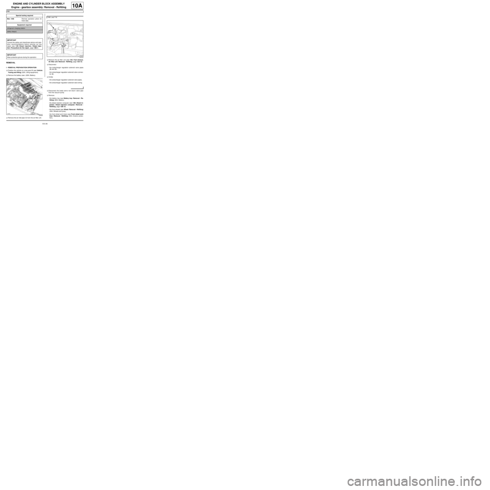
aRemove the air inlet pipe (1) from the air filter unit.aRemove the air filter unit (see 12A, Fuel mixture,
Air filter unit: Removal - Refitting, page 12A-13)
aDisconnect:
-the turbocharger regulation solenoid valve pipes
(2) and (3) ,
-the turbocharger regulation solenoid valve connec-
tor (4) .
aUnclip:
-the turbocharger regulation solenoid valve pipes,
-the turbocharger regulation solenoid valve wiring.
aDisconnect the brake servo non-return valve pipe
from the vacuum pump.
aRemove:
-the battery tray (see Battery tray: Removal - Re-
fitting) (80A, Battery),
-the diesel injection computer (see 13B, Diesel in-
jection, Diesel injection computer: Removal -
Refitting, page 13B-13) ,
-the front wheels (see Wheel: Removal - Refitting)
(35A, Wheels and tyres),
-the front wheel arch liners (see Front wheel arch
liner: Removal - Refitting) (55A, Exterior protec-
tion), Special tooling required
Mot. 1448Remote operation pliers for
hose clips .
Equipment required
refrigerant charging station
safety strap(s)
IMPORTANT
Consult the safety and cleanliness advice and oper-
ation recommendations before carrying out any
repair (see 13B, Diesel injection, Diesel injec-
tion: Precautions for the repair, page 13B-1) .
IMPORTANT
Wear protective gloves during the operation.
120038
K9K, and 718
141212