Page 65 of 101
38C-65
AFTER REPAIRClear the computer fault memory.
Carry out a road test followed by another check with the diagnostic tool
If the fault is still present, contact the Techline.
V3 MR-413-X44-38C050$102.mif
ANTI-LOCK BRAKING SYSTEM
Fault finding – Interpretation of faults38C
Bosch 8.1 ESP
Vdiag No.: 05
DF216
PRESENT
OR
STOREDSTEERING WHEEL ANGLE PROGRAMMING OFFSET
NOTESConditions for applying the fault finding procedure to stored faults:
The fault is declared present after an extended road test.
With the steering wheel horizontal and the wheels set straight ahead (the wheels must be directly in line with the
vehicle), read the value of the steering wheel angle using parameter PR033 Steering wheel angle.
If the value is not close to 0 ± 5˚, calibrate component 583 using command VP003 Steering wheel angle sensor
(see Configurations and programming).
Clear the ESP sensor offsets using command RZ011 Sensor offsets.
With the steering wheel horizontal and the wheels set straight ahead, turn the steering wheel a quarter of a turn
to the left.
Using parameter PR033 Steering wheel angle, check that the steering wheel angle value is close to - 90.
With the steering wheel horizontal and the wheels set straight ahead, turn the steering wheel a quarter of a turn
to the right.
Using parameter PR033 Steering wheel angle, check that the steering wheel angle value is close to + 90.
If the values are not correct, replace component 583 (see MR 411, Mechanical, 36A, Steering assembly,
Steering column, Removal - Refitting).
Drive in a straight line.
If the steering wheel is not horizontal when the vehicle is driving straight ahead (the vehicle "pulls" to the left or
right).
Check the conformity of the tyres, pressures, wear, and dimensions (see MR 411, Mechanical, 35A, Wheels and
tyres, Tyres: Identification and Tyre pressure, Identification).
Replace the tyre(s) if necessary (see MR 411, Mechanical, 35A, Wheels and tyres, Tyres, Removal -
Refitting).
Adjust the wheel alignment (see MR 411, Mechanical, 30A, General information, Front axle: Adjustment).
With the steering wheel horizontal and the wheels set straight ahead, calibrate component 583 using command
VP003 Steering wheel angle sensor.
Clear the ESP sensor offsets using command RZ011 Sensor offsets.
ESP_V05_DF216
Page 66 of 101
38C-66
AFTER REPAIRClear the computer fault memory.
Carry out a road test followed by another check with the diagnostic tool
If the fault is still present, contact the Techline.
V3 MR-413-X44-38C050$102.mif
ANTI-LOCK BRAKING SYSTEM
Fault finding – Interpretation of faults38C
Bosch 8.1 ESP
Vdiag No.: 05
DF300
PRESENT
OR
STOREDPUMP MOTOR CONTROL CIRCUIT
DEF: Abnormal voltage.
NOTESUse the Wiring Diagram Technical Note for New Twingo.
Check the tightness and condition of the battery terminals (see 80A, Battery).
Check the charging circuit (see 16A, Starting - Charging).
Check the condition and position of fuse F1 (40A) and F2 (30A) in the engine fuse box
(see 81C, Fuse box).
Check the connection and condition (possible wiring damage) of the connectors of components 1094, 1834,
1016 and intermediate connector R107.
If the connector is faulty (see Technical Note 6015A, Repairing electrical wiring, Wiring: Precautions for
repair), repair the connector, otherwise replace the wiring.
With the connector of component 1094 disconnected, check the insulation and continuity of connections MAH
of component 1094 (tightness, oxidation, etc.).
Connectors of components 1094, 1175, 583 and intermediate union R107 disconnected,
–check the insulation and continuity of connection AP5 between component 1094 and intermediate
connector R107.
–Check the insulation and continuity of connection AP5 between intermediate connector R107 and
component 1016.
–Check the insulation and continuity of connection BP14 between components 1094 and 1834.
–Check the insulation and continuity of connection BP8 between components 1094 and 1834.
If the connections are faulty (see Technical Note 6015A, Electrical wiring repair, Wiring: Precautions for
repair), repair the wiring, otherwise replace it.
ESP_V05_DF300
Page 67 of 101
38C-67
AFTER REPAIRClear the computer fault memory.
Carry out a road test followed by another check with the diagnostic tool
If the fault is still present, contact the Techline.
V3 MR-413-X44-38C050$102.mif
ANTI-LOCK BRAKING SYSTEM
Fault finding – Interpretation of faults38C
Bosch 8.1 ESP
Vdiag No.: 05
DF311
PRESENT
OR
STOREDNO SEQUENTIAL GEARBOX MULTIPLEX SIGNAL
NOTESSpecial notes:
Even though it is stored in the computer, this fault does not cause the warning light to
come on or a fault message, because the ESP system is not faulty.
Perform fault finding on the BVR (sequential gearbox) using the diagnostic tool.
Note:
After repairing the fault in the BVR (sequential gearbox), clear the fault memory in the
ESP system.
Priority in the event of a number of faults:
Deal with fault DF152 Multiplex network first if it is present or stored.
Conditions for applying the fault finding procedure to stored faults:
The fault is declared present when the engine is started.
Run a check on the BVR using the diagnostic tool (see 21B, Sequential gearbox).
Run a multiplex network test (see 88B, Multiplex).
ESP_V05_DF311
Page 68 of 101
38C-68
AFTER REPAIRClear the computer fault memory.
Carry out a road test followed by another check with the diagnostic tool
If the fault is still present, contact the Techline.
V3 MR-413-X44-38C050$102.mif
ANTI-LOCK BRAKING SYSTEM
Fault finding – Interpretation of faults38C
Bosch 8.1 ESP
Vdiag No.: 05
DF313
PRESENT
OR
STOREDINVALID SEQUENTIAL GEARBOX MULTIPLEX SIGNALS
NOTESSpecial notes:
The ABS/ESP system is not faulty, but has received unusable signals from the BVR.
Perform fault finding on the BVR using the diagnostic tool.
Note:
Once the fault in the sequential gearbox system has been repaired, clear the ABS/ESP
computer fault memory.
Conditions for applying the fault finding procedure to stored faults:
The fault is declared present when the engine is started.
Run a check on the BVR using the diagnostic tool (see 21B, Sequential gearbox).
Run a multiplex network test (see 88B, Multiplex).
ESP_V05_DF313
Page 69 of 101
38C-69
AFTER REPAIRClear the computer fault memory.
Carry out a road test followed by another check with the diagnostic tool
If the fault is still present, contact the Techline.
V3 MR-413-X44-38C050$102.mif
ANTI-LOCK BRAKING SYSTEM
Fault finding – Interpretation of faults38C
Bosch 8.1 ESP
Vdiag No.: 05
DF321
PRESENT
OR
STOREDCLUTCH SWITCH SIGNAL CONSISTENCY
DEF: Inoperative
NOTESSpecial notes:
The ABS/ESP system is not faulty.
Perform fault finding on the injection system using the diagnostic tool.
Note:
Once the fault in the INJECTION system has been repaired, clear the ABS/ESP
computer fault memory.
Conditions for applying the fault finding procedure to stored faults:
The fault is declared present when driving after having exceeded a speed of 42 mph
(70 km/h).
Check the injection computer (see 13B, Diesel injection or 17B, Petrol injection) using the diagnostic tool.
ESP_V05_DF321
Page 70 of 101
38C-70V3 MR-413-X44-38C050$110.mif
38C
Bosch 8.1 ESP
Vdiag No.: 05
NOTESOnly carry out this conformity check after a complete check with the diagnostic tool.
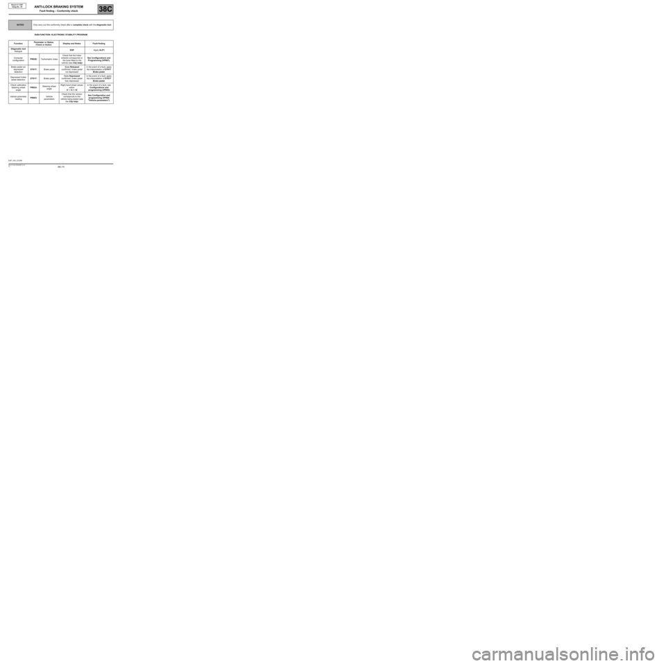
SUB-FUNCTION: ELECTRONIC STABILITY PROGRAM
FunctionParameter or Status
Check or ActionDisplay and Notes Fault finding
Diagnostic tool
dialogueESPApply ALP1
Computer
configurationPR030:Tachometric indexCheck that the index
entered corresponds to
the tyres fitted to the
vehicle (see Clip help)See Configurations and
Programming (VP007).
Brake pedal not
depressed
detectionET017:Brake pedalState Released
confirmed, brake pedal
not depressedIn the event of a fault, apply
the interpretation of ET017
Brake pedal.
Depressed brake
pedal detectionET017:Brake pedalState Depressed
confirmed, brake pedal
fully depressedIn the event of a fault, apply
the interpretation of ET017
Brake pedal.
Check calibration
Steering wheel
angle PR033:Steering wheel
angleRight-hand wheel values
within:
-5˚ < X < +5˚In the event of a fault, see
Configurations and
programming (VP003)
Vehicle parameter
readingPR063:Vehicle
parametersCheck that the version
corresponds to the
vehicle being tested (see
the Clip help)See Configuration and
programming (VP004
"Vehicle parameters").
ESP_V05_CCONF
ANTI-LOCK BRAKING SYSTEM
Fault finding – Conformity check
Page 71 of 101
38C-71V3 MR-413-X44-38C050$120.mif
38C
Bosch 8.1 ESP
Vdiag No.: 05
Tool status Diagnostic tool title
ET017Brake pedal
ET023ESP on/off button
ET030Automatic brake light lighting
ET108Steering wheel angle programming
ANTI-LOCK BRAKING SYSTEM
Fault finding – Status summary table
Page 72 of 101
38C-72
AFTER REPAIRClear the computer fault memory.
Carry out a road test followed by another check with the diagnostic tool.
V3 MR-413-X44-38C050$130.mif
38C
Bosch 8.1 ESP
Vdiag No.: 05
ET017BRAKE PEDAL
NOTESSpecial notes:
Only carry out the checks if the PRESSED and RELEASED statuses are inconsistent
with the pedal position.
Use the Wiring Diagram Technical Note for New Twingo.
"Released" STATUS Brake pedal depressed.
If the brake lights are working:
With the connectors of components 1094, 160, intermediate union R107 and component 119 disconnected
(depending on equipment), check the continuity of connection 65A between components 160 and 1094.
If the connection is faulty (see Technical Note 6015A, Electrical wiring repair, Wiring: Precautions for repair),
repair the wiring, otherwise replace it.
If the brake lights are not working:
–Check the condition, fitting and the adjustment of component 160 as well as the conformity of the bulbs.
–Remove (see MR 411, Mechanical, 37A, Mechanical component control, Brake light switch: Removal -
Refitting) and test the operation of component 160:
Continuity between tracks Insulation between tracks
Switch engaged
(Brake pedal released)AP10 and 5A AP10 and 65A
Switch released
(Brake pedal depressed)AP10 and 65A AP10 and 5A
Replace component 160 if necessary.
Check the condition and position of fuse F5 (15A) (see 81C, Fuse box).
Check for +12 V after ignition feed on connection AP10 of component 1016 to the earth MAH.
With intermediate connector R107 and component 160, 1281 and 1081 disconnected (depending on equipment):
–Check the continuity and insulation of connection AP10 between component 1016 and intermediate
connector R107.
–Check the continuity and insulation of connection AP10 between component 160 and intermediate
connector R107.
ESP_V05_ET017
ANTI-LOCK BRAKING SYSTEM
Fault finding – Interpretation of statuses