2009 OPEL ZAFIRA tow bar
[x] Cancel search: tow barPage 69 of 228

Storage
69
Load compartment
Stowage in the load
compartment To open the cover, lift the carpeting.
Raise, rotate and lift the ring. The
stowage compartment contains the
vehicle tools
3 173 and the coupling
ball bar.
The
fuse box is on the left side behind
the cover in the load compartment
side panelling 3 171.
The tyre repair kit is on the right side
behind the cover 3 179. Load compartment cover
Do not place any heavy or sharp-
edged objects on the load
compartment cover.
Before operating the load
compartment cover, the rear seat
belts
must be fed through the side belt
holders.
Opening Remove load compartment cover
from side brackets. It rolls up
automatically. Closing
Pull the cover towards the rear using
the handle and engage it in the
retainers at the sides.
Removing
Open the load compartment cover.
Pull
the release lever up and hold. Lift
cover on right side and remove from
retainers.
Page 150 of 228
150
Driving and operating
If the trailer starts snaking, drive more
slowly, do not attempt to correct the
steering and brake sharply if
necessary.
When driving downhill, drive in the
same gear as if driving uphill and
drive at a similar speed.
Adjust tyre pressure to the value
specified for full load 3 220.
Trailer towing
Trailer loads
The permissible trailer loads are
vehicle and engine-dependent
maximum values which must not be
exceeded. The actual trailer load is
the difference between the actual
gross weight of the trailer and the
actual coupling socket load with the
trailer coupled.
The permissible trailer loads are
specified
in the vehicle documents. In
general, they are valid for gradients
up to max. 12 % The permitted trailer load applies up
to the specified incline and up to an
altitude of 1000 metres above sea
level. Since engine power decreases
as altitude increases because of the
air becoming thinner, therefore
reducing climbing ability, the
permissible gross train weight also
decreases by 10 % for every 1000
metres of additional altitude. The
gross
train weight does not have to be
reduced when driving on roads with
slight inclines (less than 8 %, e. g.
motorways).
The permissible gross train weight
must not be exceeded. This weight is
specified on the identification plate
3 208.
Vertical coupling load
The vertical coupling load is the load
exerted by the trailer on the coupling
ball. It can be varied by changing the
weight distribution when loading the
trailer.
The maximum permissible vertical
coupling load (75 kg) is specified on
the towing equipment identification
plate and in the vehicle documents. Always aim for the maximum load,
especially in the case of heavy
trailers. The vertical coupling load
should never fall below 25 kg.
Rear axle load
When the trailer is coupled and the
towing vehicle fully loaded, the
permissible rear axle load (see
identification plate or vehicle
documents) may be exceeded by 90
kg
and the gross vehicle weight rating
by 75 kg. If the permissible rear axle
load is exceeded, a maximum speed
of 100 km/h applies.
Towing equipment Caution
When operating without a trailer,
remove the coupling ball bar.
Page 151 of 228
Driving and operating
151
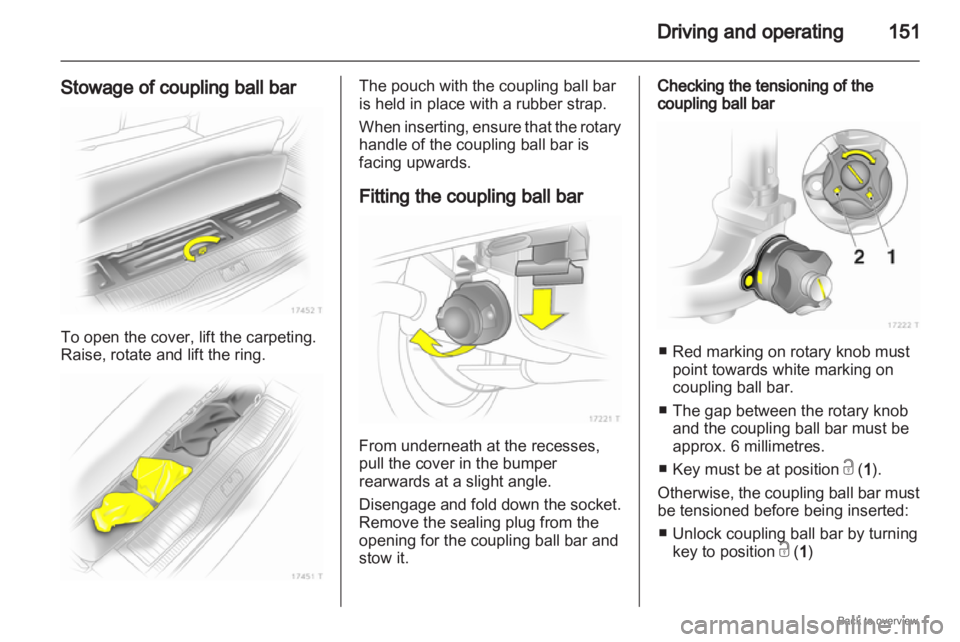
Stowage of coupling ball bar To open the cover, lift the carpeting.
Raise, rotate and lift the ring. The pouch with the coupling ball bar
is held in place with a rubber strap.
When
inserting, ensure that the rotary
handle of the coupling ball bar is
facing upwards.
Fitting the coupling ball bar From underneath at the recesses,
pull the cover in the bumper
rearwards at a slight angle.
Disengage
and fold down the socket.
Remove the sealing plug from the
opening for the coupling ball bar and
stow it. Checking the tensioning of the
coupling ball bar
■ Red marking on rotary knob must
point towards white marking on
coupling ball bar.
■
The gap between the rotary knoband the coupling ball bar must be
approx. 6 millimetres.
■ Key must be at position c (1 ).
Otherwise, the coupling ball bar must
be tensioned before being inserted: ■ Unlock coupling ball bar by turning key to position c (1 )
Page 152 of 228
152
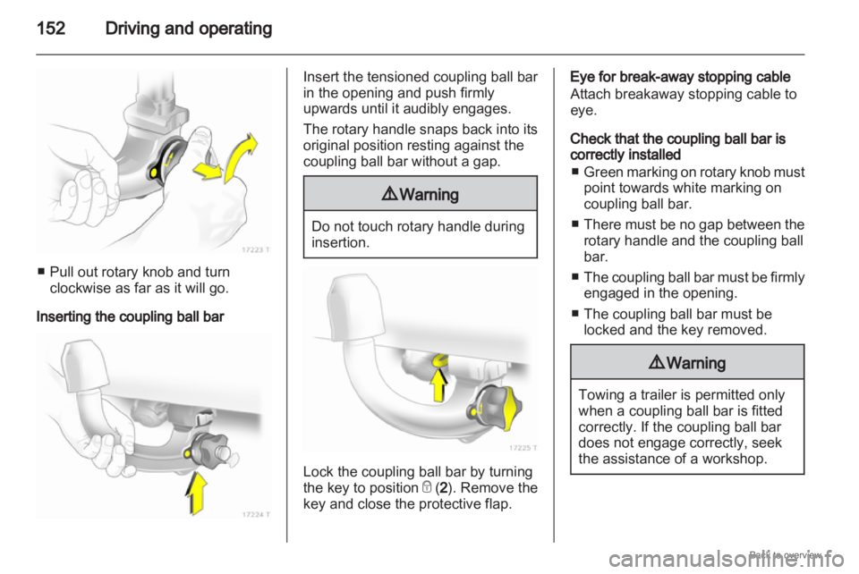
Driving and operating■ Pull out rotary knob and turn
clockwise as far as it will go.
Inserting the coupling ball bar Insert the tensioned coupling ball bar
in the opening and push firmly
upwards until it audibly engages.
The rotary handle snaps back into its
original position resting against the
coupling ball bar without a gap.
9
Warning Do not touch rotary handle during
insertion.
Lock the coupling ball bar by turning
the key to position
e (2). Remove the
key and close the protective flap. Eye for break-away stopping cable
Attach breakaway stopping cable to
eye.
Check that the coupling ball bar is
correctly installed
■ Green
marking on rotary knob must
point towards white marking on
coupling ball bar.
■ There must be no gap between the rotary handle and the coupling ball
bar.
■ The coupling ball bar must be firmly engaged in the opening.
■ The coupling ball bar must be locked and the key removed. 9
Warning Towing a trailer is permitted only
when a coupling ball bar is fitted
correctly. If the coupling ball bar
does not engage correctly, seek
the assistance of a workshop.
Page 181 of 228
Vehicle care
181
12. The prescribed tyre pressure should be obtained within 10
minutes. Tyre pressure 3 220.
When the correct pressure is
obtained, switch off the
compressor by pressing the <
button again.
If the prescribed tyre pressure is
not obtained within 10 minutes,
remove the tyre repair kit. Move
the vehicle one tyre rotation.
Reattach the tyre repair kit and
continue the filling procedure for
10 minutes. If the prescribed tyre
pressure is still not obtained, the
tyre is too badly damaged. Seek
the assistance of a workshop.
Release excess tyre pressure
using the ] button.
Do
not run the compressor longer
than 10 minutes.
13. Disconnect plug from power outlet, place in plug compartment
and remove tyre repair kit. Push
catch on bracket to remove
sealant bottle from bracket. Screw
tyre inflation hose to free
connection of sealant bottle. This prevents sealant from escaping.
Stow tyre repair kit in load
compartment.
14.
Remove any excess sealant using a cloth.
15. Take the label indicating maximum permitted speed from
the sealant bottle and affix in the
driver's field of view.
16. Continue driving immediately so that sealant is evenly distributed
in the tyre. After driving approx. 10
km (but no more than 10 minutes),
stop and check tyre pressure.
Screw compressor air hose
directly onto tyre valve and
compressor when doing this.
If tyre pressure is more than 1.3
bar, set it to the correct value.
Repeat the procedure until there
is no more loss of pressure.
If the tyre pressure has fallen
below 1.3 bar, the vehicle must
not be used. Seek the assistance
of a workshop.
17. Stow away tyre repair kit in load compartment. Note
The driving comfort of the repaired
tyre is severely affected, therefore
have this tyre replaced.
If unusual noise is heard or the
compressor becomes hot, turn
compressor off for at least 30
minutes.
The built-in safety valve opens at
a pressure of 7 bar.
The sealant can only be stored for
approximately 4 years, after which
time its sealing capability is not
longer guaranteed. Pay attention to
storage information on sealant
bottle.
Replace the used sealant bottle.
Dispose of the bottle as prescribed
by applicable laws.
The
compressor and sealant can be
used from approx. -30 °C.
The adapters supplied can be used
to pump up other items e.g.
footballs, air mattresses, inflatable
dinghies etc.
Page 191 of 228
Vehicle care
191
Towing equipment
Do not clean the coupling ball bar with
a steam-jet or high-pressure jet
cleaner.
Interior care
Interior and upholstery
Only clean the vehicle interior,
including the instrument panel fascia
and panelling, with a dry cloth or
interior cleaner.
The instrument panel should only be
cleaned using a soft damp cloth.
Clean fabric upholstery with
a vacuum cleaner and brush.
Remove stains with an upholstery
cleaner.
Clean seat belts with lukewarm water
or interior cleaner. Caution
Close Velcro fasteners as open
Velcro
fasteners on clothing could
damage seat upholstery. Plastic and rubber parts
Plastic and rubber parts can be
cleaned with the same cleaner as
used to clean the body. Use interior
cleaner if necessary. Do not use any
other
agent. Avoid solvents and petrol
in particular. Do not use high-
pressure jet cleaners.