Page 170 of 228

170
Vehicle care
No. Circuit
27
Heating, air conditioning
system, air quality sensor
28 –
29 Power steering
30 Engine electronics
31 Rear window wiper
32 Brake light switch
33 Headlight range adjustment,
light switch, clutch switch,
instrument, driver's door
module
34 Steering column control unit
35 Infotainment system
36 Cigarette lighter, front power
outlet Fuse assignments in
conjunction with load
compartment
fuse box version B
No. Circuit
1
ABS
2 ABS
3 Interior fan electronic climate
control
4 Interior fan heating and air
conditioning system
5 Radiator fan
6 Radiator fan
7 Windscreen washer system
8 Horn
9 Headlamp washer system
10 Emergency unlocking of central
locking system
11 –
12 – No. Circuit
13
Fog light
14 Windscreen wipers
15 Windscreen wipers
16 Control module electronics,
Open&Start system, ABS,
brake light switch
17 Diesel fuel filter heating
18 Starter
19 Transmission electronics
20 Air conditioning system
21 Engine electronics
22 Engine electronics
23 Adaptive Forward Lighting,
headlight range adjustment
24 Fuel pump
25 Transmission electronics
26 Engine electronics
27 Power steering
Page 171 of 228
Vehicle care
171
No. Circuit
28
Transmission electronics
29 Transmission electronics
30 Engine electronics
31 Adaptive Forward Lighting,
headlight range adjustment
32 Brake system, air conditioning
system, clutch switch
33 Adaptive Forward Lighting,
headlight range adjustment,
light switch
34 Steering column control unit
35 Infotainment system
36 Mobile telephone, digital radio,
infotainment system, display Load compartment fuse
box
The fuse box is behind a cover. Press
the locking tabs forward and remove
the cover.
Do not store any objects behind the
cover.
Depending on the equipment, there
are two different fuse boxes.
Fuse box version A
To replace a fuse, remove the
relevant protective cap. No. Circuit
1
Fog light
2 Rear power outlet
3 Load compartment power outlet
4 Reversing lamps
5 Rear power windows
6 Air conditioning system
7 Front power windows
8 Heated exterior mirrors
Page 180 of 228
180
Vehicle care
3. Position the sealant bottle on the bracket. Make sure that the bottle
does not fall. 4. Unscrew
valve cap from defective
tyre.
5. Screw tyre inflation hose to valve. 6. Screw air hose onto compressor
connection.
7.
Open cover of electricalconnection from the left and pull
out the plug. 8. Open the rear power outlet and
insert plug of tyre repair kit.
To avoid discharging the battery,
we recommend running the
engine. 9.
Press < button on the
compressor.
The tyre is filled with
sealant.
10. The compressor pressure gauge briefly indicates up to 6 bar whilst
the sealant bottle is emptying
(approx. 30 seconds). Then the
pressure starts to drop.
11. All of the sealant is pumped into the tyre. Then the tyre is inflated.
Page 186 of 228
186
Vehicle care
■ Wear eye protection and protective
clothing when handling a battery.
■ Use a booster battery with the same voltage (12 volts). Its capacity
(Ah) must not be much less than
that of the discharged battery.
■ Use jump leads with insulated terminals and a cross section of at
least 16 mm 2
(25 mm 2
for diesel
engines).
■ Do not disconnect the discharged battery from the vehicle.
■ Switch off all unnecessary electrical consumers.
■ Do not lean over the battery during jump starting.
■ Do not allow the terminals of one lead to touch those of the other
lead.
■ The vehicles must not come into contact with each other during the
jump starting process.
■ Apply the handbrake, transmission in neutral, automatic transmission
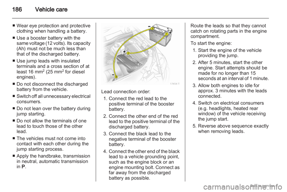
in P. Lead connection order:
1.
Connect the red lead to thepositive terminal of the booster
battery.
2. Connect the other end of the red lead to the positive terminal of the
discharged battery.
3. Connect the black lead to the negative terminal of the booster
battery.
4. Connect the other end of the black lead to a vehicle grounding point,
such as the engine block or an
engine mounting bolt. Connect as
far away from the discharged
battery as possible. Route the leads so that they cannot
catch on rotating parts in the engine
compartment.
To start the engine:
1.
Start the engine of the vehicleproviding the jump.
2. After 5 minutes, start the other engine. Start attempts should be
made for no longer than 15
seconds at an interval of 1 minute.
3. Allow both engines to idle for approx. 3 minutes with the leads
connected.
4. Switch on electrical consumers (e.g. headlights, heated rear
window) of the vehicle receiving
the jump start.
5. Reverse above sequence exactly when removing leads.
Page 187 of 228
Vehicle care
187
Towing
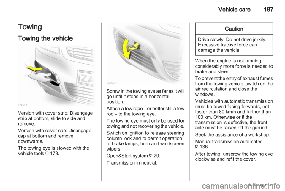
Towing the vehicle Version with cover strip: Disengage
strip at bottom, slide to side and
remove.
Version with cover cap: Disengage
cap at bottom and remove
downwards.
The towing eye is stowed with the
vehicle tools
3 173. Screw in the towing eye as far as it will
go until it stops in a horizontal
position.
Attach
a tow rope – or better still a tow
rod – to the towing eye.
The towing eye must only be used for
towing and not recovering the vehicle.
Switch on ignition to release steering
column lock and to permit operation
of brake lamps, horn and windscreen
wipers.
Open&Start system 3 29.
Transmission in neutral. Caution
Drive slowly. Do not drive jerkily.
Excessive tractive force can
damage the vehicle.
When the engine is not running,
considerably
more force is needed to
brake and steer.
To prevent the entry of exhaust fumes
from the towing vehicle, switch on the
air recirculation and close the
windows.
Vehicles with automatic transmission
must be towed facing forwards, not
faster than 80 km/h and further than
100 km. Otherwise or if the
transmission is defective, the front
axle must be raised off the ground.
Seek the assistance of a workshop.
Manual transmission automated
3 136.
After towing, unscrew the towing eye
clockwise and refit the cover.
Page 190 of 228
190
Vehicle care
Clean smearing wiper blades with
a soft cloth and window cleaner.
Moonroof
Never
clean with solvents or abrasive
agents, fuels, aggressive media (e.g.
paint cleaner, acetone-containing
solutions etc.), acidic or highly
alkaline media or abrasive pads. Do
not apply wax or polishing agents to
the middle part of the moonroof.
Wheels and tyres
Do not use high-pressure jet
cleaners.
Clean rims with a pH-neutral wheel
cleaner.
Rims are painted and can be treated
with the same agents as the body.
Paintwork damage
Rectify minor paintwork damage with
a touch-up pen before rust forms.
Have more extensive damage or rust
areas repaired by a workshop. Underbody
Some
areas of the vehicle underbody
have a PVC undercoating while other
critical areas have a durable
protective wax coating.
After the underbody is washed, check
the underbody and have it waxed if
necessary.
Bitumen/rubber materials could
damage the PVC coating. Have
underbody work carried out by
a workshop.
Before and after winter, wash the
underbody and have the protective
wax coating checked.
Engine compartment
Areas of the engine compartment that
are painted in the same colour as the
vehicle must be looked after like any
other painted surface.
It is advisable to wash the engine
compartment before and after winter
and preserve it with wax. Protect the
alternator and brake fluid reservoir
with plastic sheets before washing
the engine. When washing the engine with
a steam-jet cleaner, do not direct the
steam jet towards components of the
antilock brake system, air
conditioning system or the belt drive
and its components.
After
an engine wash, have all engine
room components preserved
thoroughly by a workshop using
protective wax.
Do not use high-pressure jet
cleaners.
Natural gas system
Do not direct the steam jet or high-
pressure jet towards natural gas
system components. It is particularly
important to protect the natural gas
tank and the pressure valves on the
vehicle underbody and the bulkhead
in the engine compartment.
These components must not be
treated using chemical cleaners or
preservatives.
Have components of the natural gas
system cleaned by a workshop
authorised to carry out maintenance
of natural gas vehicles.
Page 192 of 228
192
Service and maintenance
Service and
maintenance
General information ...................192
Scheduled maintenance ............194
Recommended
fluids, lubricants
and parts .................................... 204 General information
Service information
In order to ensure economical and
safe vehicle operation and to
maintain the value of your vehicle, it
is of vital importance that all
maintenance
work is carried out at the
proper intervals as specified.
European service intervals
Due every 30,000 km or 1 year,
whichever occurs first.
International service intervals
Due every 15,000 km or 1 year,
whichever occurs first.
Confirmations
Confirmation of service is recorded in
the Service and Warranty Booklet.
The date and mileage is completed
with the stamp and signature of the
servicing workshop.
Make sure that the Service and
Warranty Booklet is completed
correctly as continuous proof of
service is essential if any warranty or goodwill claims are to be met, and is
also a benefit when selling the
vehicle.
Fixed service interval
When
service is due, InSP appears in
the odometer display for
approximately 10 seconds when the
ignition is switched on. Have the next
service performed by a workshop
within one week or 500 km
(whichever occurs first).
Flexible service interval
The length of the service intervals is
based on several parameters
stemming from usage. For this
reason, various engine-specific data
is continually gathered and is used to
calculate the remaining distance until
the next service.
If the remaining distance is less than
1500 km, InSP is displayed with
a remaining distance of 1000 km
when the ignition is switched on and
off. If less than 1000 km remains,
InSP is displayed for several
seconds. Have the next service
Page 196 of 228
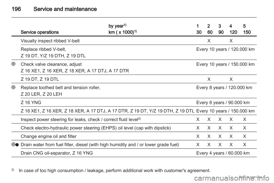
196
Service and maintenanceService operations by year
1)
km ( x 1000) 1) 1
30 2
60 3
90 4
120 5
150
Visually inspect ribbed V-belt X X
Replace ribbed V-belt,
Z 19 DT, Y/Z 19 DTH, Z 19 DTL Every 10 years / 120.000 km
+ Check valve clearance, adjust
Z 16 XE1, Z 16 XER, Z 18 XER, A 17 DTJ, A 17 DTR Every 10 years / 150.000 km
Z 19 DT, Z 19 DTL X X
+ Replace toothed belt and tension roller,
Z 20 LER, Z 20 LEH Every 8 years / 120.000 km
Z 16 YNG Every 6 years / 90.000 km
Z 16 XE1, Z 16 XER, Z 18 XER, A 17 DTJ, A 17 DTR, Z 19 DT, Y/Z 19 DTH, Z 19 DTL Every 10 years / 150.000 km
Inspect power steering for leaks, check / correct fluid level
2) X X X X X
Check electro-hydraulic power steering (EHPS) oil level (cap with dipstick) X X X X X
Change engine oil and filter X X X X X
+o Drain water from fuel filter, diesel (with high humidity and / or lower grade fuel) X X X X X
Drain CNG oil-separator, Z 16 YNG Every 4 years / 60.000 km
2)
In case of too high consumption / leakage, perform additional work with customer's agreement.