2009 NISSAN TIIDA turn
[x] Cancel search: turnPage 3 of 4331
ACC
NP
O
ACCELERATOR CONTROL SYSTEM
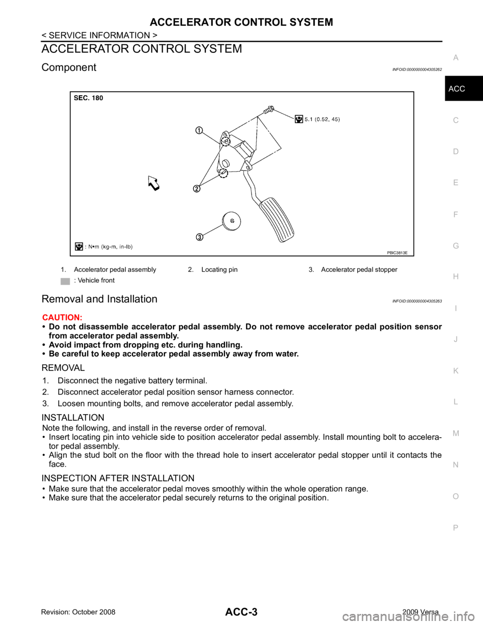
Component INFOID:0000000004305262
Removal and Installation INFOID:0000000004305263
CAUTION:
• Do not disassemble accelerator pedal assembly. Do not remove accelerator pedal position sensor
from accelerator pedal assembly.
• Avoid impact from dropping etc. during handling.
• Be careful to keep accelerator pedal assembly away from water.
REMOVAL 1. Disconnect the negative battery terminal.
2. Disconnect accelerator pedal position sensor harness connector.
3. Loosen mounting bolts, and remove accelerator pedal assembly.
INSTALLATION Note the following, and install in the reverse order of removal.
• Insert locating pin into vehicle side to position accelerator pedal assembly. Install mounting bolt to accelera- tor pedal assembly.
• Align the stud bolt on the floor with the thread hole to in sert accelerator pedal stopper until it contacts the
face.
INSPECTION AFTER INSTALLATION • Make sure that the accelerator pedal mo ves smoothly within the whole operation range.
• Make sure that the accelerator pedal securely returns to the original position. 1. Accelerator pedal assembly 2. Locating pin 3. Accelerator pedal stopper
: Vehicle front
Page 8 of 4331

AT
N
O
P
N
Wiring Diagram - AT -
SSV/B ................................
145
Diagnosis Procedure ........................................... ..146
Component Inspection ........................................ ..147
DTC P1760 OVERRUN CLUTCH SOLENOID
VALVE ............................................................ ..149
Description .......................................................... ..149
CONSULT-III Refe rence Value in Data Monitor
Mode ................................................................... ..
149
On Board Diagnosis Logic .................................. ..149
Possible Cause ................................................... ..149
DTC Confirmation Procedure .............................. ..149
Wiring Diagram - AT - OVRCSV ......................... ..150
Diagnosis Procedure ........................................... ..151
Component Inspection ........................................ ..152
DTC VEHICLE SPEED SENSOR MTR .......... ..154
Description .......................................................... ..154
CONSULT-III Refe rence Value in Data Monitor
Mode ................................................................... ..
154
On Board Diagnosis Logic .................................. ..154
Possible Cause ................................................... ..154
DTC Confirmation Procedure .............................. ..154
Wiring Diagram - AT - VSSMTR ...........................155
Diagnosis Procedure ........................................... ..156
DTC BATT/FLUID TEMP SEN (A/T FLUID
TEMP SENSOR CIRCUIT AND TCM POWER
SOURCE) ....................................................... ..
157
Description .......................................................... ..157
CONSULT-III Refe rence Value in Data Monitor
Mode ................................................................... ..
157
On Board Diagnosis Logic .................................. ..157
Possible Cause ................................................... ..157
DTC Confirmation Procedure .............................. ..157
Wiring Diagram - AT - BA/FTS ............................ ..158
Diagnosis Procedure ........................................... ..159
Component Inspection ........................................ ..161
DTC TURBINE REVOLUTION SENSOR ....... ..163
Description .......................................................... ..163
CONSULT-III Refe rence Value in Data Monitor
Mode ................................................................... ..
163
On Board Diagnosis Logic .................................. ..163
Possible Cause ................................................... ..163
DTC Confirmation Procedure .............................. ..163
Wiring Diagram - AT - PT/SEN ........................... ..164
Diagnosis Procedure ........................................... ..165
CONTROL UNIT (RAM), CONTROL UNIT
(ROM) ............................................................. ..
168
Description .......................................................... ..168
On Board Diagnosis Logic .................................. ..168
Possible Cause ................................................... ..168
DTC Confirmation Procedure .............................. ..168
Diagnosis Procedure ........................................... ..168
MAIN POWER SUPPLY AND GROUND CIR-
CUIT ................................................................ ..169
Wiring Diagram - AT - MAIN ............................... ..169 Diagnosis Procedure ...........................................
..170
PNP, OD SWITCH AND CLOSED THROT-
TLE, WIDE OPEN THROTTLE POSITION
SIGNAL CIRCUI T ............................................ 172
CONSULT-III Reference Va lue in Data Monitor
Mode .................................................................... ..
172
TCM Terminal and Refere nce Value .....................172
Diagnosis Procedure ........................................... ..172
Component Inspection ......................................... ..176
SHIFT POSITION INDICATOR CIRCUIT ........ 177
Description ........................................................... ..177
CONSULT-III Reference Va lue in Data Monitor
Mode .................................................................... ..
177
Diagnosis Procedure ........................................... ..177
TROUBLE DIAGNOSIS FOR SYMPTOMS .... 178
Wiring Diagram - AT - NONDTC ......................... ..178
OD OFF Indicator Lamp Does Not Come On ...... ..181
Engine Cannot Be Started in "P" and "N" Position ..183
In "P" Position, Vehicle Moves Forward or Back-
ward When Pushed ............................................. ..
184
In "N" Position, Vehicle Moves ............................ ..184
Large Shock "N" → "R" Position .......................... ..185
Vehicle Does Not Creep Backward in "R" Position ..186
Vehicle Does Not Creep Forw ard in "D", "2" or "1"
Position ................................................................ ..
187
Vehicle Cannot Be Started from D 1 ..................... ..188
A/T Does Not Shift: D 1→ D 2or Does Not Kick-
down: D 4→ D 2 ..................................................... ..190
A/T Does Not Shift: D 2→ D 3 ................................ ..192
A/T Does Not Shift: D 3→ D 4 ................................ ..193
A/T Does Not Perform Lock-up ........................... ..194
A/T Does Not Hold Lock-up Condition ................. ..195
Lock-up Is Not Released ..................................... ..196
Engine Speed Does Not Return to Idle (Light
Braking D 4→ D 3) ................................................. ..197
A/T Does Not Shift: D 4→ D 3, When OD OFF ...... ..198
A/T Does Not Shift: D 3→ 22, When Selector Lever
"D" → "2" Position ............................................... ..
199
A/T Does Not Shift: 2 2→ 11, When Selector Lever
"2" → "1" Position ................................................ ..
200
Vehicle Does Not Decelerate by Engine Brake ... ..202
TCM Self-Diagnosis Does Not Activate ............... ..205
A/T SHIFT LOCK SYSTEM ............................. 207
Description ........................................................... ..207
Shift Lock System Parts Location ........................ ..207
Wiring Diagram - AT - SHIFT .............................. ..208
Diagnosis Procedure ........................................... ..208
TRANSMISSION CONTROL MODULE .......... 211
Removal and Installation ..................................... ..211
SHIFT CONTROL SYSTEM ............................ 212
Control Device Removal an d Installation ...............212
Control Device Disassembly and Assembly ..........215
Selector Lever Knob Remo val and Installation ......215
Adjustment of A/T Position .................................. ..216
Page 12 of 4331

AT
N
O P
PRECAUTIONS
Precaution for Supplemental Restraint System (SRS) "AIR BAG" and "SEAT BELT
PRE-TENSIONER" INFOID:0000000004803451
The Supplemental Restraint System such as “A IR BAG” and “SEAT BELT PRE-TENSIONER”, used along
with a front seat belt, helps to reduce the risk or severi ty of injury to the driver and front passenger for certain
types of collision. This system includes seat belt switch inputs and dual stage front air bag modules. The SRS
system uses the seat belt switches to determine the front air bag deployment, and may only deploy one front
air bag, depending on the severity of a collision and w hether the front occupants are belted or unbelted.
Information necessary to service the system safely is included in the SRS and SB section of this Service Man-
ual.
WARNING:
• To avoid rendering the SRS inoper ative, which could increase the risk of personal injury or death in
the event of a collision which would result in air bag inflation, all maintenance must be performed by
an authorized NISSAN/INFINITI dealer.
• Improper maintenance, including in correct removal and installation of the SRS can lead to personal
injury caused by unintentional act ivation of the system. For removal of Spiral Cable and Air Bag
Module, see the SRS section.
• Do not use electrical test equipm ent on any circuit related to the SRS unless instructed to in this
Service Manual. SRS wiring harnesses can be identi fied by yellow and/or orange harnesses or har-
ness connectors.
• When working near the Airbag Diagnosis Sensor Un it or other Airbag System sensors with the Igni-
tion ON or engine running, DO NOT use air or el ectric power tools or strike near the sensor(s) with a
hammer. Heavy vibration could activate the sensor( s) and deploy the air bag(s), possibly causing
serious injury.
• When using air or electric power tools or hammers , always switch the Ignition OFF, disconnect the
battery, and wait at least 3 minutes before performing any service.
Precaution Necessary for Steering Wh eel Rotation After Battery Disconnect
INFOID:0000000004305289
NOTE:
• This Procedure is applied only to models with Intell igent Key system and NVIS/IVIS (NISSAN/INFINITI
VEHICLE IMMOBILIZER SYSTEM - NATS).
• Remove and install all control units after disconnecti ng both battery cables with the ignition knob in the
″ LOCK ″ position.
• Always use CONSULT-III to perform self-diagnosis as a part of each function inspection after finishing work.
If DTC is detected, perform trouble diagnosis according to self-diagnostic results.
For models equipped with the Intelligent Key system and NVIS/IVIS, an electrically controlled steering lock
mechanism is adopted on the key cylinder.
For this reason, if the battery is disconnected or if the battery is discharged, the steering wheel will lock and
steering wheel rotation will become impossible.
If steering wheel rotation is required when battery pow er is interrupted, follow the procedure below before
starting the repair operation.
OPERATION PROCEDURE 1. Connect both battery cables. NOTE:
Supply power using jumper cables if battery is discharged.
2. Use the Intelligent Key or mechanical key to turn the ignition switch to the ″ACC ″ position. At this time, the
steering lock will be released.
3. Disconnect both battery cables. The steering lock will remain released and the steering wheel can be
rotated.
4. Perform the necessary repair operation.
5. When the repair work is completed, return the ignition switch to the ″LOCK ″ position before connecting
the battery cables. (At this time, the steering lock mechanism will engage.)
6. Perform a self-diagnosis check of al l control units using CONSULT-III.
Page 18 of 4331
AT
N
O P
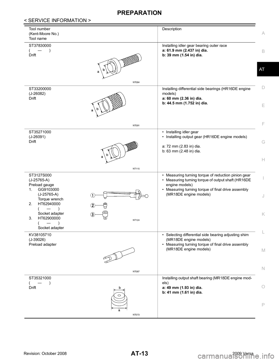
ST37830000
( — )
Drift Installing idler gear bearing outer race
a: 61.9 mm (2.437 in) dia.
b: 39 mm (1.54 in) dia.
ST33200000
(J-26082)
Drift Installing differential side bearings (HR16DE engine
models)
a: 60 mm (2.36 in) dia.
b: 44.5 mm (1.752 in) dia.
ST35271000
(J-26091)
Drift • Installing idler gear
• Installing output gear (HR16DE engine models)
a: 72 mm (2.83 in) dia.
b: 63 mm (2.48 in) dia.
ST3127S000
(J-25765-A)
Preload gauge
1. GG9103000
(J-25765-A)
Torque wrench
2. HT62940000
( — )
Socket adapter
3. HT62900000
( — )
Socket adapter • Measuring turning torque of reduction pinion gear
• Measuring turning torque of output shaft (HR16DE engine models)
• Measuring turning torque of final drive assembly
(MR18DE engine models)
KV38105710
(J-39026)
Preload adapter • Selecting differential side bearing adjusting shim
(MR18DE engine models)
• Measuring turning torque of final drive assembly (MR18DE engine models)
ST35321000
( — )
Drift Installing output shaft bearing (MR18DE engine mod-
els)
a: 49 mm (1.93 in) dia.
b: 41 mm (1.61 in) dia.
Tool number
(Kent-Moore No.)
Tool name DescriptionNT115
NT124
NT087
NT073
Page 44 of 4331
AT
N
O P
ON BOARD DIAGNOSTIC (OBD) SYSTEM
Introduction INFOID:0000000004305309
A/T system has two self-diagnostic systems.
The first is emission-related on boar d diagnostic system (OBD-II) performed by the TCM in combination with
the ECM. The malfunction is indicated by the MIL (malf unction indicator lamp) and is stored as a DTC in the
ECM memory but not the TCM memory.
The second is the TCM original self-diagnosis indicated by the OD OFF indicator lamp. The malfunction is
stored in the TCM memory. The detected items are ov erlapped with OBD-II self-diagnostic items. For detail,
refer to AT-79, " CONSULT-III Function (TRANSMISSION) " .
OBD-II Function for A/T System INFOID:0000000004305310
The ECM provides emission-related on board diagnostic (O BD-II) functions for the A/T system. One function
is to receive a signal from the TCM used with OBD-rela ted parts of the A/T system. The signal is sent to the
ECM when a malfunction occurs in the corresponding OBD-re lated part. The other function is to indicate a
diagnostic result by means of the MIL (malfunction indica tor lamp) on the instrument panel. Sensors, switches
and solenoid valves are used as sensing elements.
The MIL automatically illuminates in One or Two Trip Detection Logic when a malfunction is sensed in relation
to A/T system parts.
One or Two Trip Detection Logic of OBD-II INFOID:0000000004305311
ONE TRIP DETECTION LOGIC If a malfunction is sensed during the first test drive, the MIL will illuminate and the malfunction will be stored in
the ECM memory as a DTC. The TCM is not provided with such a memory function.
TWO TRIP DETECTION LOGIC When a malfunction is sensed during the first test drive, it is stored in the ECM memory as a 1st trip DTC
(diagnostic trouble code) or 1st trip freeze frame data. At this point, the MIL will not illuminate. — 1st trip
If the same malfunction as that experienced during the fi rst test drive is sensed during the second test drive,
the MIL will illuminate. — 2nd trip
The “trip” in the “One or Two Trip Detection Logic” m eans a driving mode in which self-diagnosis is performed
during vehicle operation.
OBD-II Diagnostic Trouble Code (DTC) INFOID:0000000004305312
HOW TO READ DTC AND 1ST TRIP DTC DTC and 1st trip DTC can be read by the following methods.
( with CONSULT-III or GST) CONSULT-III or GST (Generic Scan Tool) Examples: P0705, P0720 etc.
These DTC are prescribed by SAE J2012.
(CONSULT-III also displays the malfunctioning component or system.)
• 1st trip DTC No. is the same as DTC No.
• Output of the diagnostic troubl e code indicates that the indicated circuit has a malfunction. How-
ever, in case of the Mode II and GST, they do not indicate whether the malfunction is still occurring or
occurred in the past and returned to normal.
CONSULT-III can identify them as shown below, therefore, CONS ULT-III (if available) is recom-
mended.
DTC or 1st trip DTC of a malfunction is displayed in SELF-DIAGNOSTIC RESULTS mode for “ENGINE” with
CONSULT-III. Time data indicates how many times the vehicle was driven after the last detection of a DTC.
If the DTC is being detected curr ently, the time data will be “0”.
If a 1st trip DTC is stored in the ECM, the time data will be “1t”.
Freeze Frame Data and 1st Trip Freeze Frame Data The ECM has a memory function, which stores the driv ing condition such as fuel system status, calculated
load value, engine coolant temperature, short term f uel trim, long term fuel trim, engine speed and vehicle
speed at the moment the ECM detects a malfunction.
Page 45 of 4331

CONSULT-III Function " (HR16DE),
EC-604, " CONSULT-III Function (ENGINE) " (MR
Type 1) or EC-1116, " CONSULT-III F
unction (ENGINE) " (MR Type 2).
Only one set of freeze frame data (either 1st trip freez e frame data of freeze frame data) can be stored in the
ECM. 1st trip freeze frame data is stored in the ECM me mory along with the 1st trip DTC. There is no priority
for 1st trip freeze frame data and it is updated each time a different 1st trip DTC is detected. However, once
freeze frame data (2nd trip detection/MIL on) is stored in the ECM memory, 1st trip freeze frame data is no
longer stored. Remember, only one set of freeze frame data can be stored in the ECM. The ECM has the fol-
lowing priorities to update the data.
Both 1st trip freeze frame data and freeze frame dat a (along with the DTC) are cleared when the ECM mem-
ory is erased.
HOW TO ERASE DTC
The diagnostic trouble code can be erased by CONSULT- III, GST or ECM DIAGNOSTIC TEST MODE as
described following.
• If the battery cable is disconnected, the diagnosti c trouble code will be cleared within 24 hours.
• When you erase the DTC, using CONSULT-III or GS T is easier and quicker than switching the mode
selector on the ECM.
The following emission-related diagnostic information is cleared from the ECM memory when erasing DTC
related to OBD-II. For details, refer to EC-90, " Diagnosis Description " (HR16DE),
EC-542, " Emission-related
Diagnostic Information " (MR Type 1) or
EC-1052, " Emission-related Diagnostic Information " (MR Type 2).
• Diagnostic trouble codes (DTC)
• 1st trip diagnostic trou ble codes (1st trip DTC)
• Freeze frame data
• 1st trip freeze frame data
• System readiness test (SRT) codes
• Test values
HOW TO ERASE DTC (WITH CONSULT-III)
• If a DTC is displayed for both ECM and TCM, it is necessary to be erased for both ECM and TCM.
1. If the ignition switch stays ON after repair work, be sure to turn ignition switch OFF once. Wait at least 10 seconds and then turn it ON (engine stopped) again.
2. Turn CONSULT-III “ON” and touch “TRANSMISSION”.
3. Touch “SELF-DIAG RESULTS”.
4. Touch “ERASE”. (The DTC in the TCM will be erased.) Then touch “BACK” twice.
5. Touch “ENGINE”.
6. Touch “SELF-DIAG RESULTS”.
7. Touch “ERASE”. (The DTC in the ECM will be erased.)
HOW TO ERASE DTC (WITH GST)
1. If the ignition switch stays ON after repair work, be sure to turn ignition switch OFF once. Wait at least 10 seconds and then turn it ON (engine stopped) again.
2. Perform “TCM SELF-DIAGNOSTIC PROCEDURE (No Tools)”. Refer to AT-83, " Diagnosis Procedure
without CONSULT-III " . (The engine warm-up step can be skipped when performing the diagnosis only to
erase the DTC.)
3. Select Mode 4 with Generic Scan Tool (GST). For details, refer to EC-110, " Diagnosis Tool Function "
(HR16DE),
EC-612, " Generic Scan Tool (GST) Function " (MR Type 1) or
EC-1124, " Generic Scan Tool
(GST) Function " (MR Type 2).
HOW TO ERASE DTC (NO TOOLS)
Priority Items
1 Freeze frame data Misfire — DTC: P0300 - P0306
Fuel Injection System Function — DTC: P0171, P0172, P0174, P0175
2 Except the above items (Includes A/T related items)
3 1st trip freeze frame data
Page 46 of 4331
AT
N
O P
The OD OFF indicator lamp is located on the combination meter.
1. If the ignition switch stays ON after repair work, be su re to turn ignition switch OFF once. Wait at least 10
seconds and then turn it ON (engine stopped) again.
2. Perform “TCM SELF-DIAGNOSTIC PR OCEDURE (No Tools)”. Refer to AT-83, " Diagnosis Procedure
without CONSULT-III " . (The engine warm-up step can be ski
pped when performing the diagnosis only to
erase the DTC.)
3. Perform “OBD-II SELF-DIAGNOSTIC PROCEDURE (No tools)”. Refer to EC-90, " Diagnosis Description "
(HR16DE),
EC-542, " Emission-related Diagnostic Information " (MR Type 1) or
EC-1052, " Emission-
related Diagnostic Information " (MR Type 2).
Malfunction Indicator Lamp (MIL) INFOID:0000000004305313
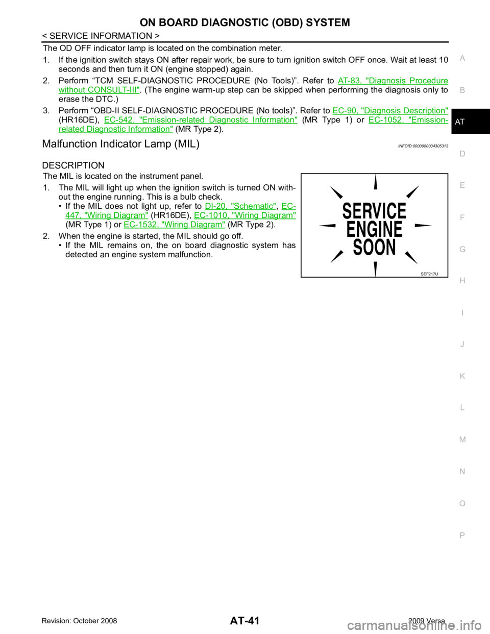
DESCRIPTION The MIL is located on the instrument panel.
1. The MIL will light up when the ignition switch is turned ON with- out the engine running. This is a bulb check.
• If the MIL does not light up, refer to DI-20, " Schematic " ,
EC- 447, " Wiring Diagram " (HR16DE),
EC-1010, " Wiring Diagram "
(MR Type 1) or
EC-1532, " Wiring Diagram " (MR Type 2).
2. When the engine is start ed, the MIL should go off.
• If the MIL remains on, the on board diagnostic system has
detected an engine system malfunction.
Page 48 of 4331
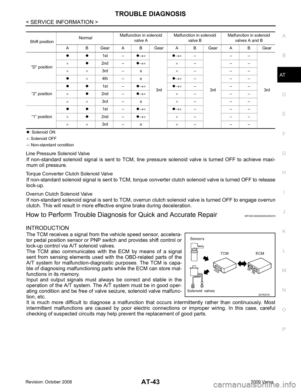
AT
N
O P
z
: Solenoid ON
× : Solenoid OFF
–: Non-standard condition
Line Pressure Solenoid Valve If non-standard solenoid signal is sent to TCM, line pre ssure solenoid valve is turned OFF to achieve maxi-
mum oil pressure.
Torque Converter Clutch Solenoid Valve If non-standard solenoid signal is sent to TCM, torque conv erter clutch solenoid valve is turned OFF to release
lock-up.
Overrun Clutch Solenoid Valve If non-standard solenoid signal is sent to TCM, overr un clutch solenoid valve is turned OFF to engage overrun
clutch. This will result in more effective engine brake during deceleration.
How to Perform Trouble Diagnosis for Quick and Accurate Repair INFOID:0000000004305316
INTRODUCTION The TCM receives a signal from the vehicle speed sensor, accelera-
tor pedal position sensor or PNP switch and provides shift control or
lock-up control via A/T solenoid valves.
The TCM also communicates with the ECM by means of a signal
sent from sensing elements used wit h the OBD-related parts of the
A/T system for malfunction-diagnostic purposes. The TCM is capa-
ble of diagnosing malfunctioning parts while the ECM can store mal-
functions in its memory.
Input and output signals must always be correct and stable in the
operation of the A/T system. T he A/T system must be in good oper-
ating condition and be free of valve seizure, solenoid valve malfunc-
tion, etc.
It is much more difficult to diagnose a malfunction t hat occurs intermittently rather than continuously. Most
intermittent malfunctions are caused by poor electric c onnections or improper wiring. In this case, careful
checking of suspected circuits may hel p prevent the replacement of good parts.
Shift position
Normal
Malfunction in solenoid
valve A Malfunction in solenoid
valve B Malfunction in solenoid
valves A and B
A B Gear A B Gear A B Gear A B Gear
“D” position z z
1st –z→×
3rd z
→× –
3rd – –
3rd
×
z2nd – z→× × – – –
× × 3rd – x ×– – –
z ×4th – x z→× – – –
“2” position z z
1st –z→× z→× – – –
× z2nd – z→× × – – –
× × 3rd – x ×– – –
“1” position z z
1st –z→× z→× – – –
× z2nd – z→× × – – –
× × 3rd – x ×– – –