2009 NISSAN TIIDA ignition switch
[x] Cancel search: ignition switchPage 407 of 4331
AV
N
O P
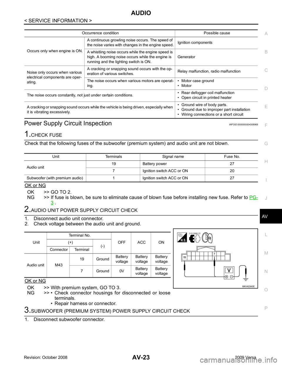
Power Supply Circuit Inspection
INFOID:0000000004306968OK >> GO TO 2.
NG >> If fuse is blown, be sure to eliminate cause of blown fuse before installing new fuse. Refer to PG-3 .
OK >> With premium system, GO TO 3.
NG >> • Check connector housings for disconnected or loose terminals.
• Repair harness or connector. Unit Terminals Signal name Fuse No.
Audio unit 19 Battery power 27
7 Ignition switch ACC or ON 20
Subwoofer (with premium audio) 1 Ignition switch ACC or ON 27 Unit
Terminal No.
OFF ACC ON
(+)
(-)
Connector Terminal
Audio unit M43 19 Ground
Battery
voltage Battery
voltage Battery
voltage
7 Ground 0V Battery
voltage Battery
voltage
Page 417 of 4331
AUDIO
AV-33
< SERVICE INFORMATION >
C
D E
F
G H
I
J
L
M A
B AV
N
O P
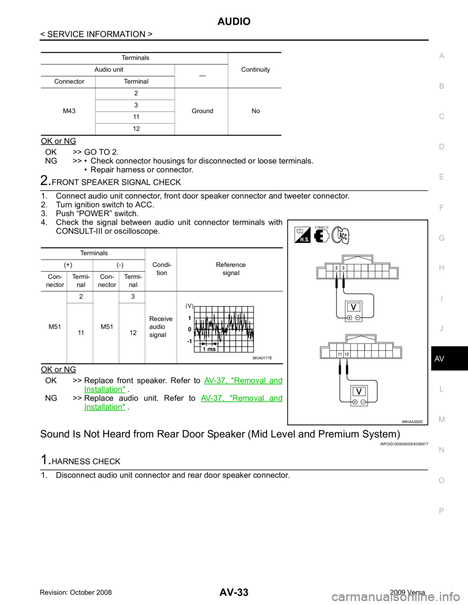
OK or NG OK >> GO TO 2.
NG >> • Check connector housings for disconnected or loose terminals.
• Repair harness or connector. 2.
FRONT SPEAKER SIGNAL CHECK
1. Connect audio unit connector, front door speaker connector and tweeter connector.
2. Turn ignition switch to ACC.
3. Push “POWER” switch.
4. Check the signal between audio unit connector terminals with CONSULT-III or oscilloscope.
OK or NG OK >> Replace front speaker. Refer to
AV-37, " Removal and
Installation " .
NG >> Replace audio unit. Refer to AV-37, " Removal and
Installation " .
Sound Is Not Heard from Rear Door Sp eaker (Mid Level and Premium System)
INFOID:00000000043069771.
HARNESS CHECK
1. Disconnect audio unit connector and rear door speaker connector. Terminals
Continuity
Audio unit
—
Connector Terminal
M43 2
Ground No
3
11
12 Terminals
Condi-tion Reference
signal
(+) (-)
Con-
nector Termi-
nal Con-
nector Termi-
nal
M51 2
M51 3
Receive
audio
signal
11 12 WKIA5352ESKIA0177E
Page 418 of 4331
AV-34< SERVICE INFORMATION >
AUDIO
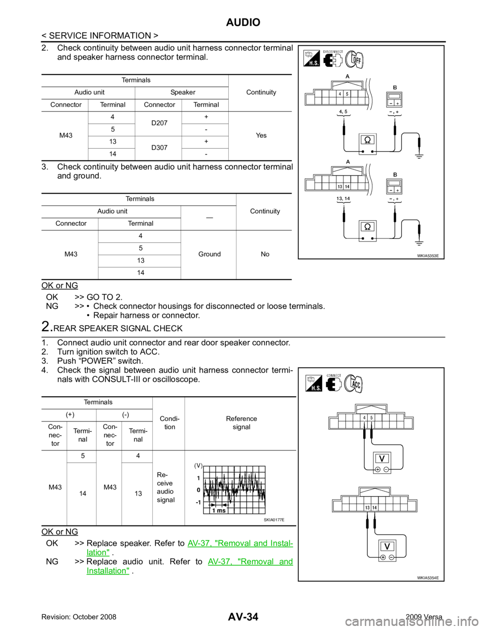
2. Check continuity between audio unit harness connector terminal and speaker harness connector terminal.
3. Check continuity between audio unit harness connector terminal and ground.
OK or NG OK >> GO TO 2.
NG >> • Check connector housings for disconnected or loose terminals.
• Repair harness or connector. 2.
REAR SPEAKER SIGNAL CHECK
1. Connect audio unit connector and rear door speaker connector.
2. Turn ignition switch to ACC.
3. Push “POWER” switch.
4. Check the signal between audio unit harness connector termi-
nals with CONSULT-III or oscilloscope.
OK or NG OK >> Replace speaker. Refer to
AV-37, " Removal and Instal-
lation " .
NG >> Replace audio unit. Refer to AV-37, " Removal and
Installation " .
Terminals
Continuity
Audio unit Speaker
Connector Terminal Connector Terminal
M43 4
D207 +
Yes
5 -
13 D307 +
14 -
Terminals Continuity
Audio unit
—
Connector Terminal
M43 4
Ground No
5
13
14 WKIA5353E
Terminals
Condi-tion Reference
signal
(+) (-)
Con- nec- tor Termi-
nal Con-
nec- tor Termi-
nal
M43 5
M43 4
Re-
ceive
audio
signal
14 13 WKIA5354ESKIA0177E
Page 429 of 4331
AV
N
O P
tooth cellular telephones may not be recognized by t
he Bluetooth control unit. When a cellular telephone or
the Bluetooth control unit is replaced, the telephone must be paired with the Bluetooth control unit. Different
cellular telephones may have different pairing procedures. Refer to the cellular telephone operating manual.
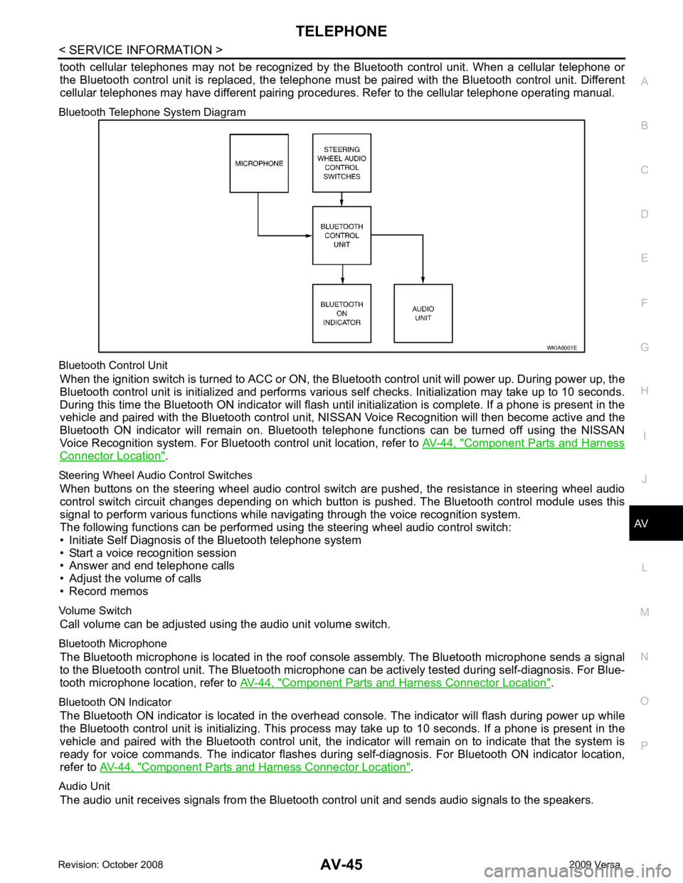
Bluetooth Telephone System Diagram
Bluetooth Control Unit When the ignition switch is turned to ACC or ON, the Bluetooth control unit will power up. During power up, the
Bluetooth control unit is initialized and performs various self checks. Initialization may take up to 10 seconds.
During this time the Bluetooth ON indicator will flash until initialization is complete. If a phone is present in the
vehicle and paired with the Bluetooth control unit, NIS SAN Voice Recognition will then become active and the
Bluetooth ON indicator will remain on. Bluetooth te lephone functions can be turned off using the NISSAN
Voice Recognition system. For Bluetooth control unit location, refer to AV-44, " Component Parts and Harness
Connector Location " .
Steering Wheel Audio Control Switches When buttons on the steering wheel audio control switch are pushed, the resistance in steering wheel audio
control switch circuit changes depending on which button is pushed. The Bluetooth control module uses this
signal to perform various functions while navigating through the voice recognition system.
The following functions can be performed usi ng the steering wheel audio control switch:
• Initiate Self Diagnosis of the Bluetooth telephone system
• Start a voice recognition session
• Answer and end telephone calls
• Adjust the volume of calls
• Record memos
Volume Switch Call volume can be adjusted using the audio unit volume switch.
Bluetooth Microphone The Bluetooth microphone is located in the roof c onsole assembly. The Bluetooth microphone sends a signal
to the Bluetooth control unit. The Bluetooth microphone can be actively tested during self-diagnosis. For Blue-
tooth microphone location, refer to AV-44, " Component Parts and Harness Connector Location " .
Bluetooth ON Indicator The Bluetooth ON indicator is located in the overhead console. The indicator will flash during power up while
the Bluetooth control unit is initializing. This process may take up to 10 seconds. If a phone is present in the
vehicle and paired with the Bluetooth control unit, the indi cator will remain on to indicate that the system is
ready for voice commands. The indicator flashes duri ng self-diagnosis. For Bluetooth ON indicator location,
refer to AV-44, " Component Parts and Harness Connector Location " .
Audio Unit The audio unit receives signals from the Bluetooth control unit and sends audio signals to the speakers.
Page 433 of 4331
AV
N
O P
Bluetooth Control Unit
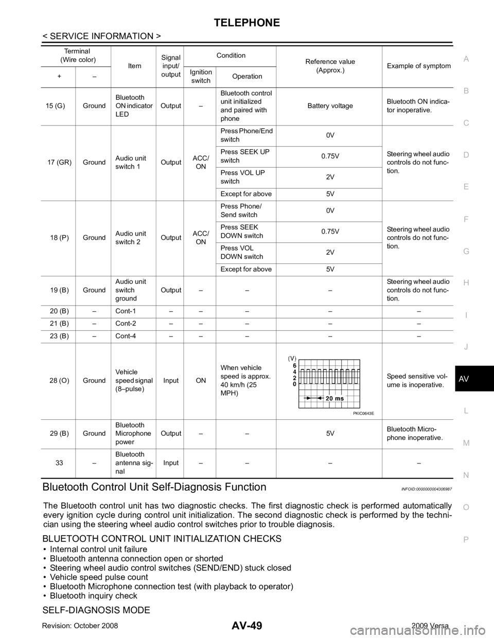
Self-Diagnosis Function INFOID:0000000004306987
The Bluetooth control unit has two diagnostic checks. The first diagnostic check is performed automatically
every ignition cycle during control unit initialization. The second diagnostic check is performed by the techni-
cian using the steering wheel audio control switches prior to trouble diagnosis.
BLUETOOTH CONTROL UNIT INITIALIZATION CHECKS
• Internal control unit failure
• Bluetooth antenna connection open or shorted
• Steering wheel audio control swit ches (SEND/END) stuck closed
• Vehicle speed pulse count
• Bluetooth Microphone connection test (with playback to operator)
• Bluetooth inquiry check
SELF-DIAGNOSIS MODE 15 (G) Ground
Bluetooth
ON indicator
LED Output – Bluetooth control
unit initialized
and paired with
phone Battery voltage
Bluetooth ON indica-
tor inoperative.
17 (GR) Ground Audio unit
switch 1 OutputACC/
ON Press Phone/End
switch 0V
Steering wheel audio
controls do not func-
tion.
Press SEEK UP
switch 0.75V
Press VOL UP
switch 2V
Except for above 5V
18 (P) Ground Audio unit
switch 2 OutputACC/
ON Press Phone/
Send switch 0V
Steering wheel audio
controls do not func-
tion.
Press SEEK
DOWN switch 0.75V
Press VOL
DOWN switch 2V
Except for above 5V
19 (B) Ground Audio unit
switch
ground Output – – – Steering wheel audio
controls do not func-
tion.
20 (B) – Cont-1 – – – – –
21 (B) – Cont-2 – – – – –
23 (B) – Cont-4 – – – – –
28 (O) Ground Vehicle
speed signal
(8–pulse) Input ON When vehicle
speed is approx.
40 km/h (25
MPH) Speed sensitive vol-
ume is inoperative.
29 (B) Ground Bluetooth
Microphone
power Output – – 5V
Bluetooth Micro-
phone inoperative.
33 – Bluetooth
antenna sig-
nal Input – – – –
Terminal
(Wire color) ItemSignal
input/
output Condition
Reference value
(Approx.) Example of symptom
+ – Ignition
switch Operation
Page 435 of 4331
AV
N
O P
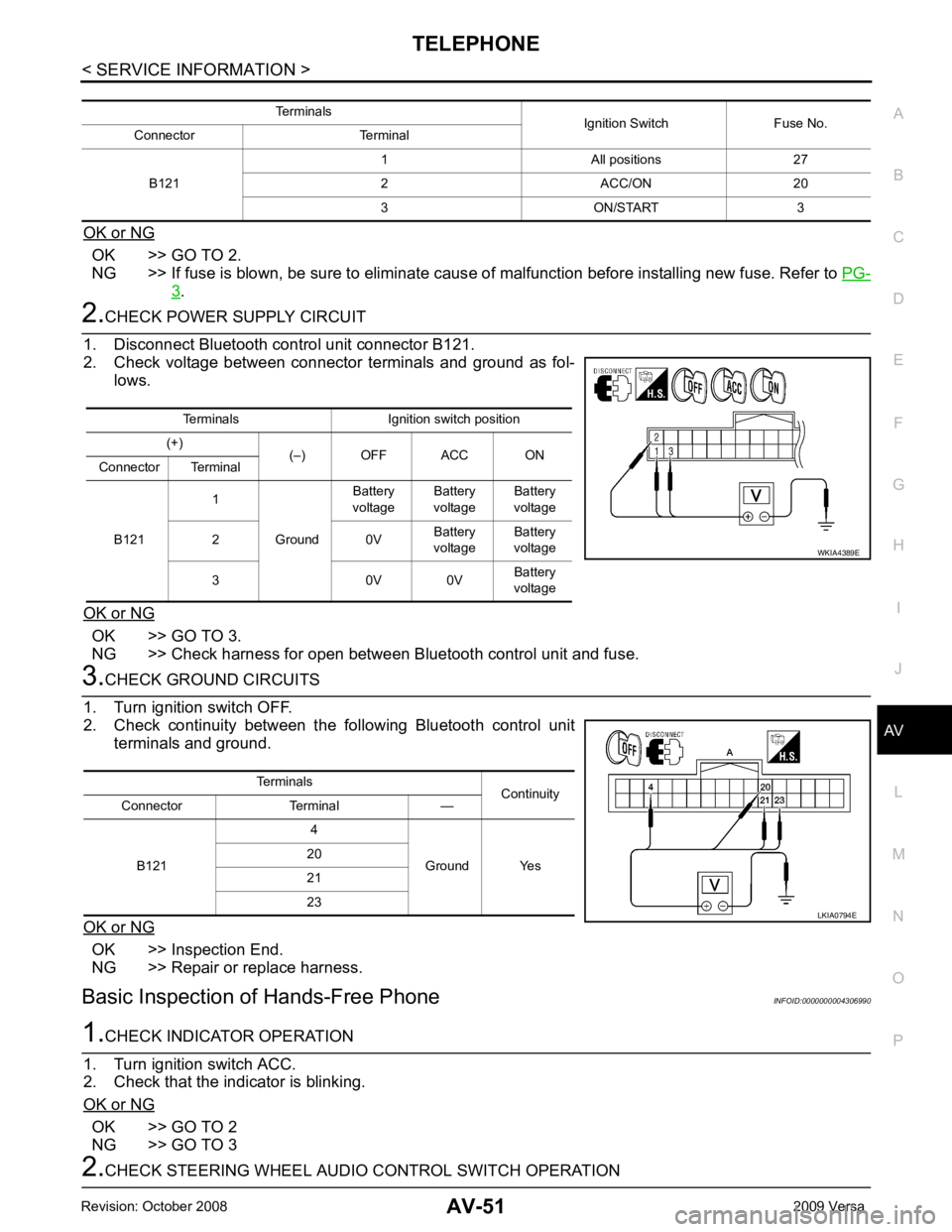
OK or NG OK >> GO TO 2.
NG >> If fuse is blown, be sure to eliminate caus e of malfunction before installing new fuse. Refer to PG-3 .
OK >> GO TO 3.
NG >> Check harness for open between Bluetooth control unit and fuse. OK >> Inspection End.
NG >> Repair or replace harness.
Basic Inspection of Hands-Free Phone INFOID:0000000004306990OK >> GO TO 2
NG >> GO TO 3 Terminals Ignition switch position
(+) (–) OFF ACC ON
Connector Terminal
B121 1
Ground Battery
voltage Battery
voltage Battery
voltage
2 0V Battery
voltage Battery
voltage
3 0V 0V Battery
voltage
Page 447 of 4331
BCS
N
O P
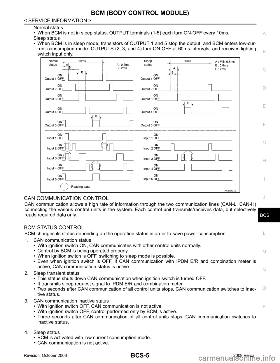
Normal status
• When BCM is not in sleep status, OUTPUT te rminals (1-5) each turn ON-OFF every 10ms.
Sleep status
• When BCM is in sleep mode, transistors of OUTP UT 1 and 5 stop the output, and BCM enters low-cur-
rent-consumption mode. OUTPUTS (2, 3, and 4) turn ON-OFF at 60ms intervals, and receives lighting
switch input only.
CAN COMMUNICATION CONTROL CAN communication allows a high rate of information through the two communication lines (CAN-L, CAN-H)
connecting the various control units in the system. Each control unit transmits/receives data, but selectively
reads required data only.
BCM STATUS CONTROL BCM changes its status depending on the operation stat us in order to save power consumption.
1. CAN communication status • With ignition switch ON, CAN communicates with other control units normally.
• Control by BCM is being operated properly.
• When ignition switch is OFF, switching to sleep mode is possible.
• Even when ignition switch is OFF, if CAN co mmunication with IPDM E/R and combination meter is
active, CAN communication status is active.
2. Sleep transient status • This status shuts down CAN communication when ignition switch is turned OFF.
• It transmits sleep request signal to IPDM E/R and combination meter.
• Two seconds after CAN communication of all control units stops, CAN communication switches to inac-
tive status.
3. CAN communication inactive status • With ignition switch OFF, CAN communication is not active.
• With ignition switch OFF, control performed only by BCM is active.
• Three seconds after CAN communication of all cont rol units stops, CAN communication switches to
inactive status.
4. Sleep status • BCM is activated with low current consumption mode.
• CAN communication is not active.
Page 448 of 4331

System Description " .
• Remote keyless entry system. Refer to BL-58, " System Description " .
• Power window system (with power windows). Refer to GW-19, " System Description " .
NOTE
• Sunroof system (with sunroof). Refer to RF-11, " System Description " .
NOTE
• Room lamp timer. Refer to LT-91, " System Description " .
• Rear wiper and washer system (Hatchback). Refer to WW-25, " System Description " .
NOTE:
Power supply only. No system control.
SYSTEMS CONTROLLED BY BCM AND IPDM E/R
• Panic system. Refer to BL-58, " System Description " .
• Vehicle security (theft warning) system. Refer to BL-219, " System Description " .
• NVIS(NATS) system. Refer to BL-248, " System Description " .
• Headlamp, tail lamp and battery saver control systems. Refer to LT-73, " System Description " ,
LT-4, " System
Description " or
LT-25, " System Description " .
• Front fog lamp (with front fog lamps). Refer to LT-39, " System Description " .
• Front wiper and washer system. Refer to WW-3, " System Description " .
• Rear window defogger system. Refer to GW-51, " System Description " .
SYSTEMS CONTROLLED BY BCM AND COMBINATION METER
• Warning chime. Refer to DI-42, " System Description " .
• Turn signal and hazard warning lamps. Refer to LT-48, " System Description " .
SYSTEMS CONTROLLED BY BCM AND INTELLIGENT KEY UNIT (WITH INTELLIGENT KEY)
• Intelligent Key system. Refer to BL-88, " System Description " .
MAJOR COMPONENTS AND CONTROL SYSTEM
System Input Output
Remote keyless entry system (with
power door locks) Remote keyless entry receiver
(keyfob) • All door locking actuators
• Turn signal lamp (LH, RH)
• Combination meter (turn signal lamp)
Intelligent Key system (with Intelligent
Key) Intelligent Key unit• All door locking actuators
• Turn signal lamp (LH, RH)
• Combination meter (turn signal lamp)
Power door lock system (with power
door locks) Front power door lock/unlock
switch (LH, RH) All door locking actuators
Power supply (IGN/RAP) to power
window (with power windows) Ignition retained power supply Power supply to power window and sunroof system
Power supply (BAT) to power window
(with power windows) Battery power supply Power supply to power window and sunroof system