2009 NISSAN TIIDA e control
[x] Cancel search: e controlPage 1825 of 4331
![NISSAN TIIDA 2009 Service Repair Manual EC
NP
O
73 P
Intake valve timing control
solenoid valve [Engine is running]
• Warm-up condition
• Idle speed BATTERY VOLTAGE
(11 - 14 V)
[Engine is running]
• Warm-up condition
• When revving NISSAN TIIDA 2009 Service Repair Manual EC
NP
O
73 P
Intake valve timing control
solenoid valve [Engine is running]
• Warm-up condition
• Idle speed BATTERY VOLTAGE
(11 - 14 V)
[Engine is running]
• Warm-up condition
• When revving](/manual-img/5/57398/w960_57398-1824.png)
EC
NP
O
73 P
Intake valve timing control
solenoid valve [Engine is running]
• Warm-up condition
• Idle speed BATTERY VOLTAGE
(11 - 14 V)
[Engine is running]
• Warm-up condition
• When revving engine up to 2,000 rpm quick- ly 7 - 10 V
74 W Sensor power supply
(Refrigerant pressure
sensor) [Ignition switch: ON]
Approximately 5 V
75 BR Sensor power supply
[Crankshaft position sensor
(POS)] [Ignition switch: ON]
Approximately 5 V
76 W EVAP control system pres-
sure sensor power supply [Ignition switch: ON]
Approximately 5 V
78 O Sensor power supply
[Camshaft position sensor
(PHASE)] [Ignition switch: ON]
Approximately 5 V
83 P CAN communication line — —
84 L CAN communication line — —
88 LG DATA link connector — —
93 O Ignition switch [Ignition switch: OFF]
0V
[Ignition switch: ON] BATTERY VOLTAGE
(11 - 14 V)
99 R Stop lamp switch [Ignition switch: OFF]
• Brake pedal: Fully released Approximately 0 V
[Ignition switch: OFF]
• Brake pedal: Slightly depressed BATTERY VOLTAGE
(11 - 14 V)
102 SB Sensor power supply
(Accelerator pedal position
sensor 2) [Ignition switch: ON]
Approximately 5 V
103 GR Accelerator pedal position
sensor 2 [Ignition switch: ON]
• Engine stopped
• Accelerator pedal: Fully released 0.3 - 0.6 V
[Ignition switch: ON]
• Engine stopped
• Accelerator pedal: Fully depressed 1.95 - 2.4 V
104 Y Sensor ground
(Accelerator pedal position
sensor 2) [Engine is running]
• Warm-up condition
• Idle speed Approximately 0 V
105 G Power supply for ECM [Ignition switch: ON]BATTERY VOLTAGE
(11 - 14 V)
106 P Sensor power supply
(Accelerator pedal position
sensor 1) [Ignition switch: ON]
Approximately 5 V
108 B ECM ground [Engine is running]
• Idle speed Body ground
TERMI-
NAL
NO. WIRE
COLOR ITEM CONDITION DATA (DC Voltage)
Page 1827 of 4331

EC
NP
O
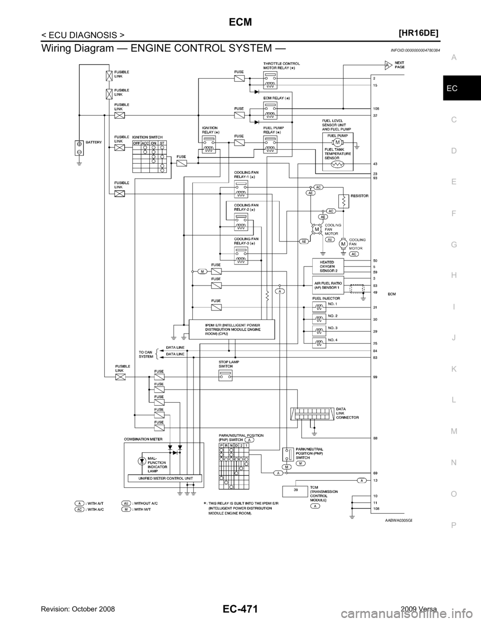
Wiring Diagram — ENGI
NE CONTROL SYSTEM — INFOID:0000000004780384 B
Page 1829 of 4331

EC
NP
O
DTC RELATED ITEM
Detected items
Engine operating condition in
fail-safe mode Remarks
Malfunction indicator
lamp circuit Engine speed will not rise
more than 2,500 rpm due to
the fuel cut When there is an open circuit on MIL circuit, the ECM cannot warn the driver by
lighting up MIL when there is malfunction on engine control system.
Therefore, when electrical controlled throttle and part of ECM related diagnoses
are continuously detected as NG for 5 trips, ECM warns the driver that engine
control system malfunctions and MIL circuit is open by means of operating fail-
safe function.
The fail-safe function also operates when above diagnoses except MIL circuit
are detected and demands the driver to repair the malfunction. DTC No. Detected items Engine operating condition in fail-safe mode
P0011 Intake valve timing control The signal is not energized to the intake valve timing control solenoid valve and the valve control does not function.
P0102
P0103 Mass air flow sensor circuit Engine speed will not rise more than 2,400 rpm due to the fuel cut.
P0117
P0118 Engine coolant tempera-
ture sensor circuit Engine coolant temperature will be determined by ECM based on the following condition.
CONSULT-III displays the engine coolant temperature decided by ECM.
Condition Engine coolant temperature decided
(CONSULT-III display)
Just as ignition switch is turned ON
or START 40
°C (104 °F)
More than approx. 4 minutes after
engine starting 80
°C (176 °F)
Except as shown above 40 - 80
°C (104 - 176 °F)
(Depends on the time)
When the fail-safe system for engine coolant temperature sensor is activated, the cooling
fan operates while engine is running.
P0122
P0123
P0222
P0223
P2135 Throttle position sensor The ECM controls the electric throttle control actuator in regulating the throttle opening in
order for the idle position to be within +10 degrees.
The ECM regulates the opening speed of the throttle valve to be slower than the normal
condition.
So, the acceleration will be poor.
P0643 Sensor power supply ECM stops the electric throttle control actuator control, throttle valve is maintained at a fixed opening (approx. 5 degrees) by the return spring.
P0605 ECM (When ECM calculation function is malfunctioning:) ECM stops the electric throttle control actuator control, throttle valve is maintained at a
fixed opening (approx. 5 degrees) by the return spring.
P1805 Brake switch ECM controls the electric throttle control actuator by regulating the throttle opening to a small range.
Therefore, acceleration will be poor.
Vehicle condition Driving condition
When engine is idling Normal
When accelerating Poor acceleration
P2100
P2103 Throttle control motor relay ECM stops the electric throttle control actuator control, throttle valve is maintained at a
fixed opening (approx. 5 degrees) by the return spring.
P2101 Electric th rottle control
function ECM stops the electric throttle control actuator control, throttle valve is maintained at a
fixed opening (approx. 5 degrees) by the return spring.
P2118 Throttle control motor ECM stops the electric throttle control actuator control, throttle valve is maintained at a fixed opening (approx. 5 degrees) by the return spring.
Page 1831 of 4331

EC
NP
O
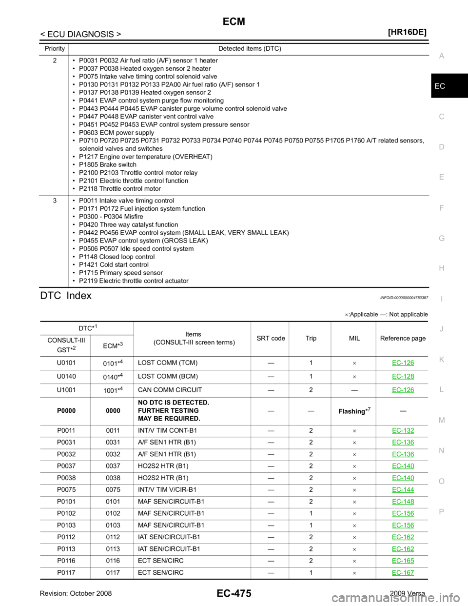
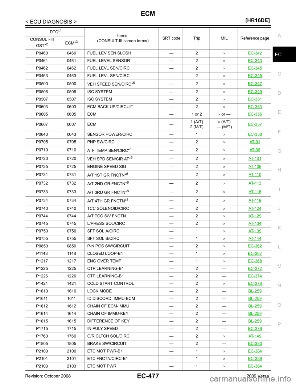
DTC Index
INFOID:0000000004780387
× :Applicable —: Not applicable
2 • P0031 P0032 Air fuel ratio (A/F) sensor 1 heater
• P0037 P0038 Heated oxygen sensor 2 heater
• P0075 Intake valve timing control solenoid valve
• P0130 P0131 P0132 P0133 P2A00 Air fuel ratio (A/F) sensor 1
• P0137 P0138 P0139 Heated oxygen sensor 2
• P0441 EVAP control system purge flow monitoring
• P0443 P0444 P0445 EVAP canister purge volume control solenoid valve
• P0447 P0448 EVAP canister vent control valve
• P0451 P0452 P0453 EVAP control system pressure sensor
• P0603 ECM power supply
• P0710 P0720 P0725 P0731 P0732 P0733 P0734 P0740 P0744 P0745 P0750 P0755 P1705 P1760 A/T related sensors,
solenoid valves and switches
• P1217 Engine over temperature (OVERHEAT)
• P1805 Brake switch
• P2100 P2103 Throttle control motor relay
• P2101 Electric throttle control function
• P2118 Throttle control motor
3 • P0011 Intake valve timing control • P0171 P0172 Fuel injection system function
• P0300 - P0304 Misfire
• P0420 Three way catalyst function
• P0442 P0456 EVAP control system (SMALL LEAK, VERY SMALL LEAK)
• P0455 EVAP control system (GROSS LEAK)
• P0506 P0507 Idle speed control system
• P1148 Closed loop control
• P1421 Cold start control
• P1715 Primary speed sensor
• P2119 Electric throttle control actuator
Priority Detected items (DTC) DTC*
1
Items
(CONSULT-III screen terms) SRT code Trip MIL Reference page
CONSULT-III
GST* 2
ECM*3
U0101 0101*4
LOST COMM (TCM) — 1 ×EC-126 U0140
0140*4
LOST COMM (BCM) — 1 ×EC-128 U1001
1001*4
CAN COMM CIRCUIT — 2 — EC-126P0031 0031 A/F SEN1 HTR (B1) — 2
×EC-136 P0032 0032 A/F SEN1 HTR (B1) — 2
×EC-136 P0037 0037 HO2S2 HTR (B1) — 2
×EC-140 P0038 0038 HO2S2 HTR (B1) — 2
×EC-140 P0075 0075 INT/V TIM V/CIR-B1 — 2
×EC-144 P0101 0101 MAF SEN/CIRCUIT-B1 — 2
×EC-148 P0102 0102 MAF SEN/CIRCUIT-B1 — 1
×EC-156 P0103 0103 MAF SEN/CIRCUIT-B1 — 1
×EC-156 P0112 0112 IAT SEN/CIRCUIT-B1 — 2
×EC-162 P0113 0113 IAT SEN/CIRCUIT-B1 — 2
×EC-162 P0116 0116 ECT SEN/CIRC — 2
×EC-165 P0117 0117 ECT SEN/CIRC — 1
×EC-167
Page 1832 of 4331

P0122 0122 TP SEN 2/CIRC-B1 — 1
×EC-171 P0123 0123 TP SEN 2/CIRC-B1 — 1
×EC-171 P0125 0125 ECT SENSOR — 2
×EC-175 P0127 0127 IAT SENSOR-B1 — 2
×EC-178 P0128 0128 THERMSTAT FNCTN — 2
×EC-180 P0130 0130 A/F SENSOR1 (B1) — 2
×EC-182 P0131 0131 A/F SENSOR1 (B1) — 2
×EC-188 P0132 0132 A/F SENSOR1 (B1) — 2
×EC-193 P0133 0133 A/F SENSOR1 (B1)
×2 ×EC-198 P0137 0137 HO2S2 (B1)
×2 ×EC-204 P0138 0138 HO2S2 (B1)
×2 ×EC-212 P0139 0139 HO2S2 (B1)
×2 ×EC-221 P0171 0171 FUEL SYS-LEAN-B1 — 2
×EC-229 P0172 0172 FUEL SYS-RICH-B1 — 2
×EC-235 P0181 0181 FTT SENSOR — 2
×EC-240 P0182 0182 FTT SEN/CIRCUIT — 2
×EC-245 P0183 0183 FTT SEN/CIRCUIT — 2
×EC-245 P0222 0222 TP SEN 1/CIRC-B1 — 1
×EC-249 P0223 0223 TP SEN 1/CIRC-B1 — 1
×EC-249 P0300 0300 MULTI CYL MISFIRE — 1 or 2
×EC-253 P0301 0301 CYL 1 MISFIRE — 1 or 2
×EC-253 P0302 0302 CYL 2 MISFIRE — 1 or 2
×EC-253 P0303 0303 CYL 3 MISFIRE — 1 or 2
×EC-253 P0304 0304 CYL 4 MISFIRE — 1 or 2
×EC-253 P0327 0327 KNOCK SEN/CIRC-B1 — 2 —
EC-259P0328 0328 KNOCK SEN/CIRC-B1 — 2 —
EC-259P0335 0335 CKP SEN/CIRCUIT — 2
×EC-263 P0340 0340 CMP SEN/CIRC-B1 — 2
×EC-268 P0420 0420 TW CATALYST SYS-B1
×2 ×EC-273 P0441 0441 EVAP PURG FLOW/MON
×2 ×EC-278 P0442 0442 EVAP SMALL LEAK
×2 ×EC-284 P0443 0443 PURG VOLUME CONT/V — 2
×EC-291 P0444 0444 PURG VOLUME CONT/V — 2
×EC-297 P0445 0445 PURG VOLUME CONT/V — 2
×EC-297 P0447 0447 VENT CONTROL VALVE — 2
×EC-301 P0448 0448 VENT CONTROL VALVE — 2
×EC-306 P0451 0451 EVAP SYS PRES SEN — 2
×EC-312 P0452 0452 EVAP SYS PRES SEN — 2
×EC-315 P0453 0453 EVAP SYS PRES SEN — 2
×EC-322 P0455 0455 EVAP GROSS LEAK — 2
×EC-329 P0456 0456 EVAP VERY SML LEAK
×*6
2 ×EC-335 DTC*
1
Items
(CONSULT-III screen terms) SRT code Trip MIL Reference page
CONSULT-III
GST* 2
ECM*3
Page 1833 of 4331

EC
NP
O
P0460 0460 FUEL LEV SEN SLOSH — 2
×EC-342 P0461 0461 FUEL LEVEL SENSOR — 2
×EC-343 P0462 0462 FUEL LEVL SEN/CIRC — 2
×EC-345 P0463 0463 FUEL LEVL SEN/CIRC — 2
×EC-345 P0500 0500
VEH SPEED SEN/CIRC*5
— 2 ×EC-347 P0506 0506 ISC SYSTEM — 2
×EC-349 P0507 0507 ISC SYSTEM — 2
×EC-351 P0603 0603 ECM BACK UP/CIRCUIT — 2
×EC-353 P0605 0605 ECM — 1 or 2
× or — EC-355 P0607 0607 ECM —
1 (A/T)
2 (M/T) ×
(A/T)
— (M/T) EC-357 P0643 0643 SENSOR POWER/CIRC — 1
×EC-358 P0705 0705 PNP SW/CIRC — 2
×AT-91 P0710 0710
ATF TEMP SEN/CIRC*8
— 2 ×AT-96 P0720 0720
VEH SPD SEN/CIR AT*5
— 2 ×AT-101 P0725 0725 ENGINE SPEED SIG — 2
×AT-106 P0731 0731
A/T 1ST GR FNCTN*8
— 2 ×AT-110 P0732 0732
A/T 2ND GR FNCTN*8
— 2 ×AT-113 P0733 0733
A/T 3RD GR FNCTN*8
— 2 ×AT-116 P0734 0734
A/T 4TH GR FNCTN*8
— 2 ×AT-119 P0740 0740 TCC SOLENOID/CIRC — 2
×AT-124 P0744 0744 A/T TCC S/V FNCTN — 2
×AT-129 P0745 0745 L/PRESS SOL/CIRC — 2
×AT-134 P0750 0750 SFT SOL A/CIRC — 1
×AT-139 P0755 0755 SFT SOL B/CIRC — 1
×AT-144 P0850 0850 P-N POS SW/CIRCUIT — 2
×EC-362 P1148 1148 CLOSED LOOP-B1 — 1
×EC-367 P1217 1217 ENG OVER TEMP — 1
×EC-368 P1225 1225 CTP LEARNING-B1 — 2 —
EC-372P1226 1226 CTP LEARNING-B1 — 2 —
EC-374P1421 1421 COLD START CONTROL — 2
×EC-376 P1610 1610 LOCK MODE — 2 —
BL-259P1611 1611 ID DISCORD, IMMU-ECM — 2 —
BL-259P1612 1612 CHAIN OF ECM-IMMU — 2 —
BL-259P1614 1614 CHAIN OF IMMU-KEY — 2 —
BL-259P1615 1615 DIFFERENCE OF KEY — 2 —
BL-259P1715 1715 IN PULY SPEED — 2 —
EC-378P1760 1760 O/R CLTCH SOL/CIRC — 2
×AT-149 P1805 1805 BRAKE SW/CIRCUIT — 2 —
EC-380P2100 2100 ETC MOT PWR-B1 — 1
×EC-384 P2101 2101 ETC FNCTN/CIRC-B1 — 1
×EC-388 P2103 2103 ETC MOT PWR — 1
×EC-384 DTC*
1
Items
(CONSULT-III screen terms) SRT code Trip MIL Reference page
CONSULT-III
GST* 2
ECM*3
Page 1839 of 4331

EC
NP
O
EGR
SYSTEM 31H EGR function P0400 80H 96H
Low Flow Faults: EGR temp change
rate (short term)
P0400 81H 96H Low Flow Faults: EGR temp change
rate (long term)
P0400 82H 96H Low Flow Faults: Difference between
max EGR temp and EGR temp under
idling condition
P0400 83H 96H Low Flow Faults: Max EGR temp
P1402 84H 96H High Flow Faults: EGR temp increase
rate
VVT
SYSTEM 35H VVT Monitor (Bank1)
P0011 80H 9DH
VTC intake function diagnosis (VTC
alignment check diagnosis)
P0014 81H 9DH VTC exhaust function diagnosis (VTC
alignment check diagnosis)
P0011 82H 9DH VTC intake function diagnosis (VTC
drive failure diagnosis)
P0014 83H 9DH VTC exhaust function diagnosis (VTC
drive failure diagnosis)
36H VVT Monitor (Bank2) P0021 80H 9DH
VTC intake function diagnosis (VTC
alignment check diagnosis)
P0024 81H 9DH VTC exhaust function diagnosis (VTC
alignment check diagnosis)
P0021 82H 9DH VTC intake function diagnosis (VTC
drive failure diagnosis)
P0024 83H 9DH VTC exhaust function diagnosis (VTC
drive failure diagnosis)
EVAP
SYSTEM 39H
EVAP control system leak
(Cap Off) P0455 80H 0CH
Difference in pressure sensor output
voltage before and after pull down
3BH EVAP control system leak
(Small leak) P0442 80H 05H
Leak area index (for more than 0.04
inch)
3CH EVAP control system leak
(Very small leak) P0456 80H 05H
Leak area index (for more than 0.02
inch)
P0456 81H FDH Maximum internal pressure of EVAP
system during monitoring
3DH Purge flow system P0441 83H 0CH Difference in pressure sensor output
voltage before and after vent control
valve close
O2 SEN-
SOR
HEATER 41H
A/F sensor 1 heater
(Bank 1) Low Input:P0031
High Input:P0032 81H 0BHConverted value of Heater electric cur-
rent to voltage
42H Heated oxygen sensor 2 heat-
er (Bank 1) Low Input:P0037
High Input:P0038 80H 0CH
Converted value of Heater electric cur-
rent to voltage
43H Heated oxygen sensor 3 heat-
er (Bank 1) P0043 80H 0CHConverted value of Heater electric cur-
rent to voltage
45H A/F sensor 1 heater
(Bank 2) Low Input:P0051
High Input:P0052 81H 0BHConverted value of Heater electric cur-
rent to voltage
46H Heated oxygen sensor 2 heat-
er (Bank 2) Low Input:P0057
High Input:P0058 80H 0CH
Converted value of Heater electric cur-
rent to voltage
47H Heated oxygen sensor 3 heat-
er (Bank 2) P0063 80H 0CHConverted value of Heater electric cur-
rent to voltage
Item
OBD-
MID Self-diagnostic test item DTC Test value and Test
limit
(GST display) Description
TID Unit and
Scaling ID
Page 1843 of 4331

EC
NP
O
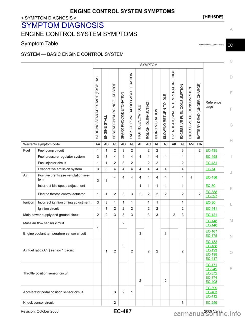
SYMPTOM DIAGNOSIS
ENGINE CONTROL SYSTEM SYMPTOMS
Symptom Table INFOID:0000000004780390
SYSTEM — BASIC ENGINE CONTROL SYSTEM SYMPTOM
Reference
pageHARD/NO START/RESTART (EXCP. HA)
ENGINE STALL
HESITATION/SURGING/FLAT SPOT
SPARK KNOCK/DETONATION
LACK OF POWER/POOR ACCELERATION
HIGH IDLE/LOW IDLE
ROUGH IDLE/HUNTING
IDLING VIBRATION
SLOW/NO RETURN TO IDLE
OVERHEATS/WATER TEMPERATURE HIGH
EXCESSIVE FUEL CONSUMPTION
EXCESSIVE OIL CONSUMPTION
BATTERY DEAD (UNDER CHARGE)
Warranty symptom code AA AB AC AD AE AF AG AH AJ AK AL AM HA
Fuel Fuel pump circuit 1 1 2 3 2 2 2 3 2 EC-435Fuel pressure regulator system 3 3 4 4 4 4 4 4 4 4
EC-498Fuel injector circuit 1 1 2 3 2 2 2 2
EC-431Evaporative emission system 3 3 4 4 4 4 4 4 4 4
EC-74Air Positive crankcase ventilation sys-
tem 3 34 4 4 4 4 4 4 4 1
EC-456Incorrect idle speed adjustment 1 1 1 1 1
EC-30Electric throttle control actuator 1 1 2 3 3 2 2 2 2 2 2
EC-388 EC-397
Ignition Incorrect ignition timing adjustment 3 3 1 1 1 1 1 1
EC-30Ignition circuit 1 1 2 2 2 2 2 2
EC-441Main power supply and ground circuit 2 2 3 3 3 3 3 2 3
EC-121Mass air flow sensor circuit
1
1 2 2
2 2 2 2 EC-148 EC-148
Engine coolant temperature sensor circuit
33 3
EC-167 EC-175
Air fuel ratio (A/F) sensor 1 circuit
EC-182 EC-188
EC-193
EC-198
EC-417
Throttle position sensor circuit
2 2EC-171 EC-249
EC-372
EC-374
EC-408
Accelerator pedal position sensor circuit 3 2 1
EC-399 EC-403
EC-412
Knock sensor circuit 2 3
EC-259