2009 NISSAN TIIDA Keyless
[x] Cancel search: KeylessPage 637 of 4331
BL-176< SERVICE INFORMATION >
BACK DOOR LOCK
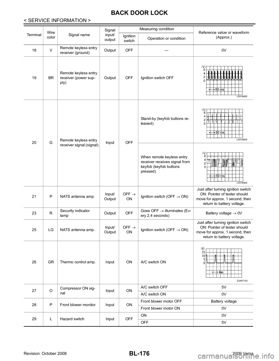
18 V Remote keyless entry
receiver (ground) Output OFF — 0V
19 BR Remote keyless entry
receiver (power sup-
ply) Output OFF Ignition switch OFF
20 G Remote keyless entry
receiver signal (signal) Input OFFStand-by (keyfob buttons re-
leased)
When remote keyless entry
receiver receives signal from
keyfob (keyfob buttons
pressed)
21 P NATS antenna amp. Input/
Output OFF
→
ON Ignition switch (OFF
→ ON) Just after turning ignition switch
ON: Pointer of tester should
move for approx. 1 second, then return to battery voltage.
23 R Security indicator
lamp Output OFFGoes OFF
→ illuminates (Ev-
ery 2.4 seconds) Battery voltage
→ 0V
25 LG NATS antenna amp. Input/
Output OFF
→
ON Ignition switch (OFF
→ ON) Just after turning ignition switch
ON: Pointer of tester should
move for approx. 1 second, then
return to battery voltage.
26 GR Thermo control amp. Input ON A/C switch ON
27 O Compressor ON sig-
nal Input ONA/C switch OFF 5V
A/C switch ON 0V
28 P Front blower monitor Input ON Front blower motor OFF Battery voltage
Front blower motor ON 0V
29 L Hazard switch Input OFF ON 0V
OFF 5V
Terminal
Wire
color Signal name Signal
input/
output Measuring condition
Reference value or waveform
(Approx.)
Ignition
switch Operation or condition LIIA1893E
LIIA1894E
LIIA1895E
ZJIA0719J
Page 661 of 4331
BL-200< SERVICE INFORMATION >
TRUNK LID OPENER
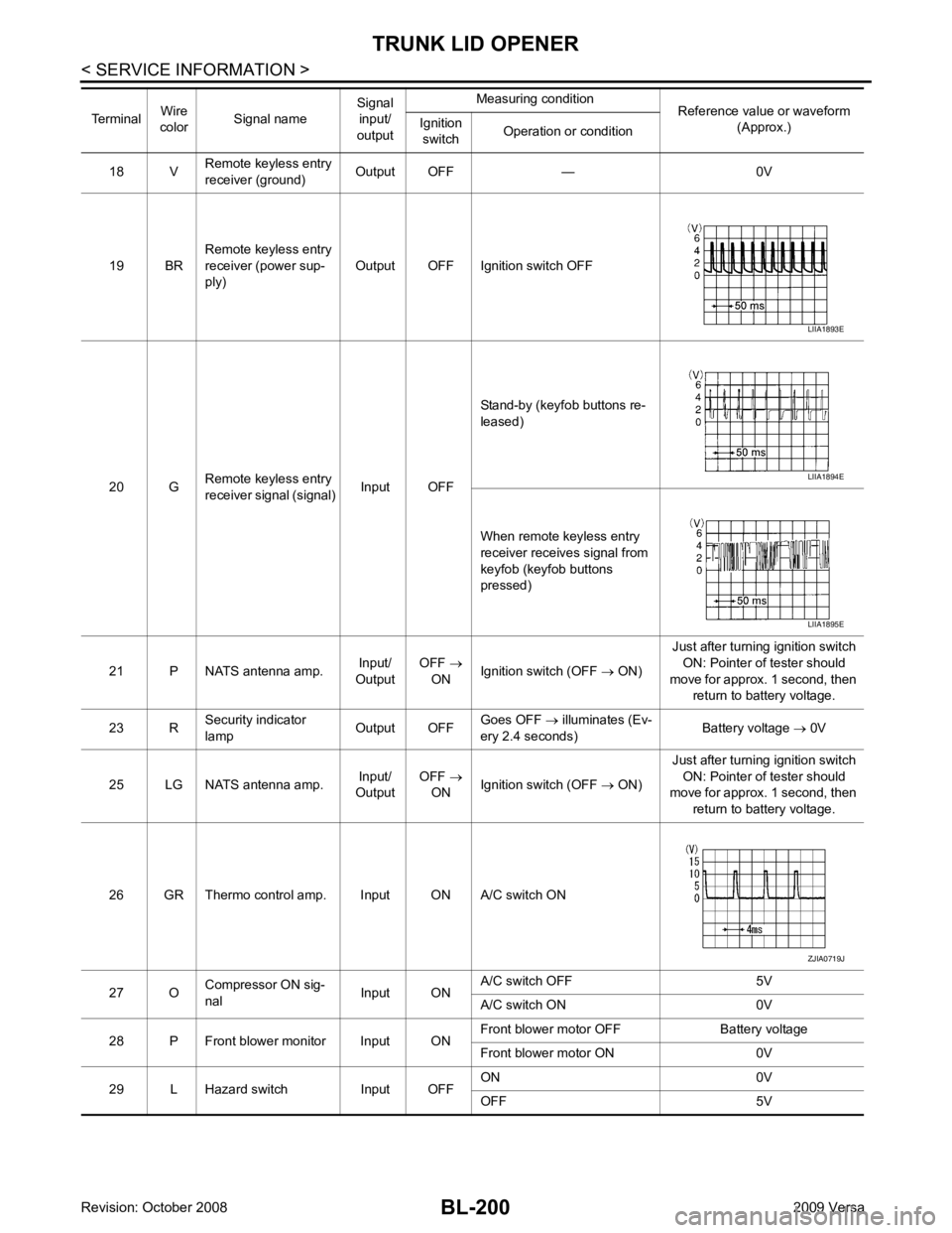
18 V Remote keyless entry
receiver (ground) Output OFF — 0V
19 BR Remote keyless entry
receiver (power sup-
ply) Output OFF Ignition switch OFF
20 G Remote keyless entry
receiver signal (signal) Input OFFStand-by (keyfob buttons re-
leased)
When remote keyless entry
receiver receives signal from
keyfob (keyfob buttons
pressed)
21 P NATS antenna amp. Input/
Output OFF
→
ON Ignition switch (OFF
→ ON) Just after turning ignition switch
ON: Pointer of tester should
move for approx. 1 second, then return to battery voltage.
23 R Security indicator
lamp Output OFFGoes OFF
→ illuminates (Ev-
ery 2.4 seconds) Battery voltage
→ 0V
25 LG NATS antenna amp. Input/
Output OFF
→
ON Ignition switch (OFF
→ ON) Just after turning ignition switch
ON: Pointer of tester should
move for approx. 1 second, then
return to battery voltage.
26 GR Thermo control amp. Input ON A/C switch ON
27 O Compressor ON sig-
nal Input ONA/C switch OFF 5V
A/C switch ON 0V
28 P Front blower monitor Input ON Front blower motor OFF Battery voltage
Front blower motor ON 0V
29 L Hazard switch Input OFF ON 0V
OFF 5V
Terminal
Wire
color Signal name Signal
input/
output Measuring condition
Reference value or waveform
(Approx.)
Ignition
switch Operation or condition LIIA1893E
LIIA1894E
LIIA1895E
ZJIA0719J
Page 689 of 4331
BL-228< SERVICE INFORMATION >
VEHICLE SECURITY (T
HEFT WARNING) SYSTEM
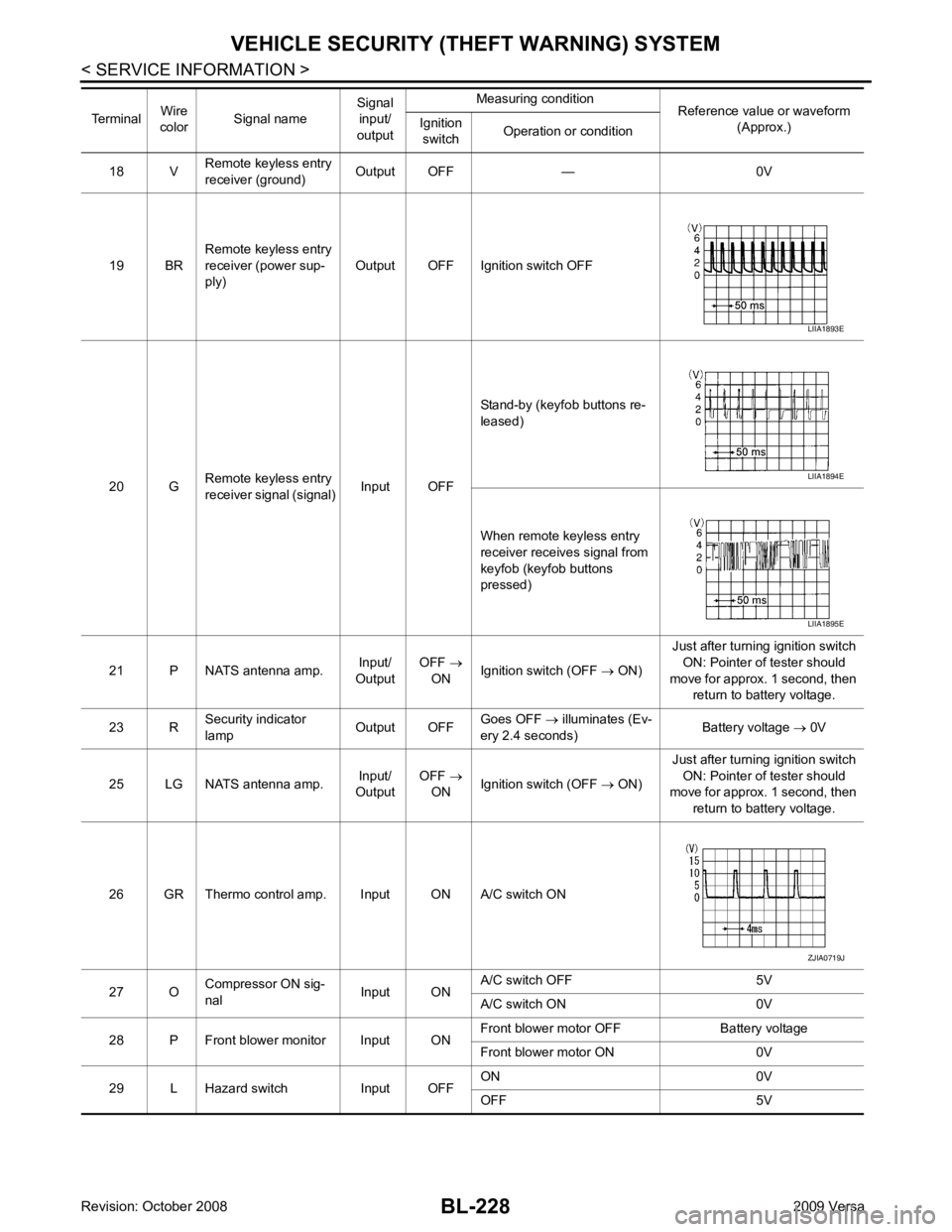
18 V Remote keyless entry
receiver (ground) Output OFF — 0V
19 BR Remote keyless entry
receiver (power sup-
ply) Output OFF Ignition switch OFF
20 G Remote keyless entry
receiver signal (signal) Input OFFStand-by (keyfob buttons re-
leased)
When remote keyless entry
receiver receives signal from
keyfob (keyfob buttons
pressed)
21 P NATS antenna amp. Input/
Output OFF
→
ON Ignition switch (OFF
→ ON) Just after turning ignition switch
ON: Pointer of tester should
move for approx. 1 second, then return to battery voltage.
23 R Security indicator
lamp Output OFFGoes OFF
→ illuminates (Ev-
ery 2.4 seconds) Battery voltage
→ 0V
25 LG NATS antenna amp. Input/
Output OFF
→
ON Ignition switch (OFF
→ ON) Just after turning ignition switch
ON: Pointer of tester should
move for approx. 1 second, then
return to battery voltage.
26 GR Thermo control amp. Input ON A/C switch ON
27 O Compressor ON sig-
nal Input ONA/C switch OFF 5V
A/C switch ON 0V
28 P Front blower monitor Input ON Front blower motor OFF Battery voltage
Front blower motor ON 0V
29 L Hazard switch Input OFF ON 0V
OFF 5V
Terminal
Wire
color Signal name Signal
input/
output Measuring condition
Reference value or waveform
(Approx.)
Ignition
switch Operation or condition LIIA1893E
LIIA1894E
LIIA1895E
ZJIA0719J
Page 695 of 4331
![NISSAN TIIDA 2009 Service Repair Manual Monitored Item Description
IGN ON SW Indicates [ON/OFF] condition of ignition switch.
ACC ON SW Indicates [ON/OFF] condition of ignition switch in ACC position.
KEYLESS LOCK* Indicates [ON/OFF] condit](/manual-img/5/57398/w960_57398-694.png "NISSAN TIIDA 2009 Service Repair Manual Monitored Item Description
IGN ON SW Indicates [ON/OFF] condition of ignition switch.
ACC ON SW Indicates [ON/OFF] condition of ignition switch in ACC position.
KEYLESS LOCK* Indicates [ON/OFF] condit")
Monitored Item Description
IGN ON SW Indicates [ON/OFF] condition of ignition switch.
ACC ON SW Indicates [ON/OFF] condition of ignition switch in ACC position.
KEYLESS LOCK* Indicates [ON/OFF] condit ion of lock signal from keyfob.
KEYLESS UNLOCK* Indicates [ON/OFF] condit ion of unlock signal from keyfob.
I-KEY LOCK** Indicates [ON/OFF] condition of lock signal from keyfob.
I-KEY UNLOCK** Indicates [ON/OFF] condition of unlock signal from keyfob.
I-KEY TRUNK** Indicates [ON/OFF] conditio n of trunk open signal from keyfob.
TRNK OPNR SW Indicates [ON/OFF] condition of trunk opener switch.
TRUNK CYL SW Indicates [ON/OFF] condit ion of trunk key cylinder switch.
TRNK OPN MNTR Indicates [ON/OFF] condition of trunk lid status.
DOOR SW-DR Indicates [ON/OFF] condition of front door switch LH.
DOOR SW-AS Indicates [ON/OFF] condition of front door switch RH.
DOOR SW-RR Indicates [ON/OFF] condition of rear door switch RH.
DOOR SW-RL Indicates [ON/OFF] condition of rear door switch LH.
BACK DOOR SW Indicates [ON/OFF] condition of back door switch.
KEY CYL LK SW Indicates [ON/OFF] condition of lock signal from key cylinder switch.
KEY CYL UN SW Indicates [ON/OFF] condition of unlock signal from key cylinder switch.
CDL LOCK SW Indicates [ON/OFF] condition of lock signal from door lock/unlock switch LH and RH.
CDL UNLOCK SW Indicates [ON/OFF] condition of unlock signal from door lock/unlock switch LH and RH. Test Item Description
THEFT IND This test is able to check security indicator lamp operation. The lamp will be turned on when “ON”
on CONSULT-III screen is touched.
VEHICLE SECURITY HORN This test is able to check vehicle security horn operation. The horns will be activated for 0.5 sec-
onds after “ON” on CONSULT-III screen is touched.
HEADLAMP (HI) This test is able to check vehicle security lamp operation. The headlamps will be activated for 0.5
seconds after “ON” on CONSULT-III screen is touched.
Page 696 of 4331
BL
N
O P
Trouble Diagnosis
INFOID:0000000004305123
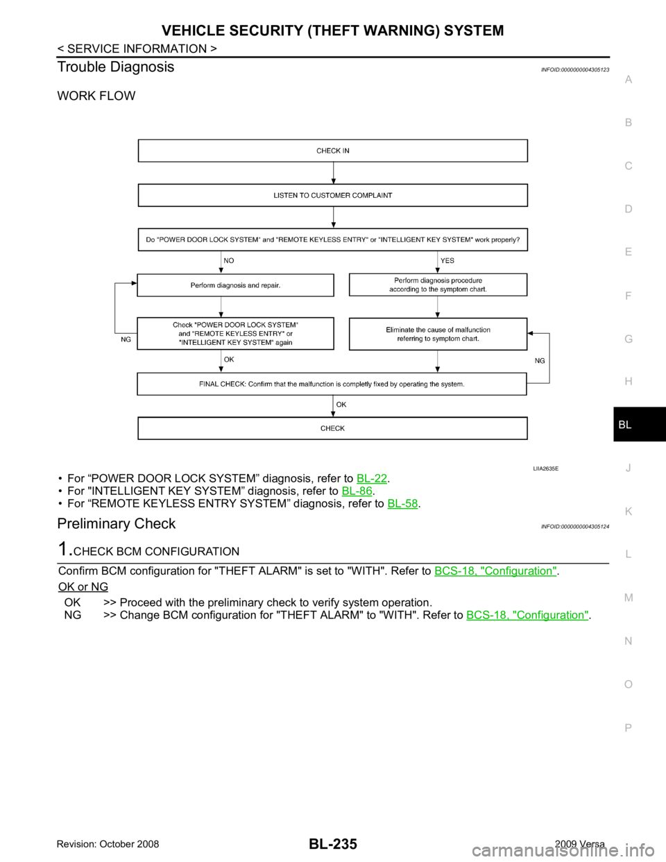
WORK FLOW
• For “POWER DOOR LOCK SYSTEM” diagnosis, refer to BL-22 .
• For "INTELLIGENT KEY SYSTEM” diagnosis, refer to BL-86 .
• For “REMOTE KEYLESS ENTRY SYSTEM” diagnosis, refer to BL-58 .
Preliminary Check INFOID:0000000004305124 Configuration " .
OK or NG OK >> Proceed with the preliminary check to verify system operation.
NG >> Change BCM configuration for "THEFT ALARM" to "WITH". Refer to BCS-18, " Configuration " .
Page 698 of 4331
BL
N
O P
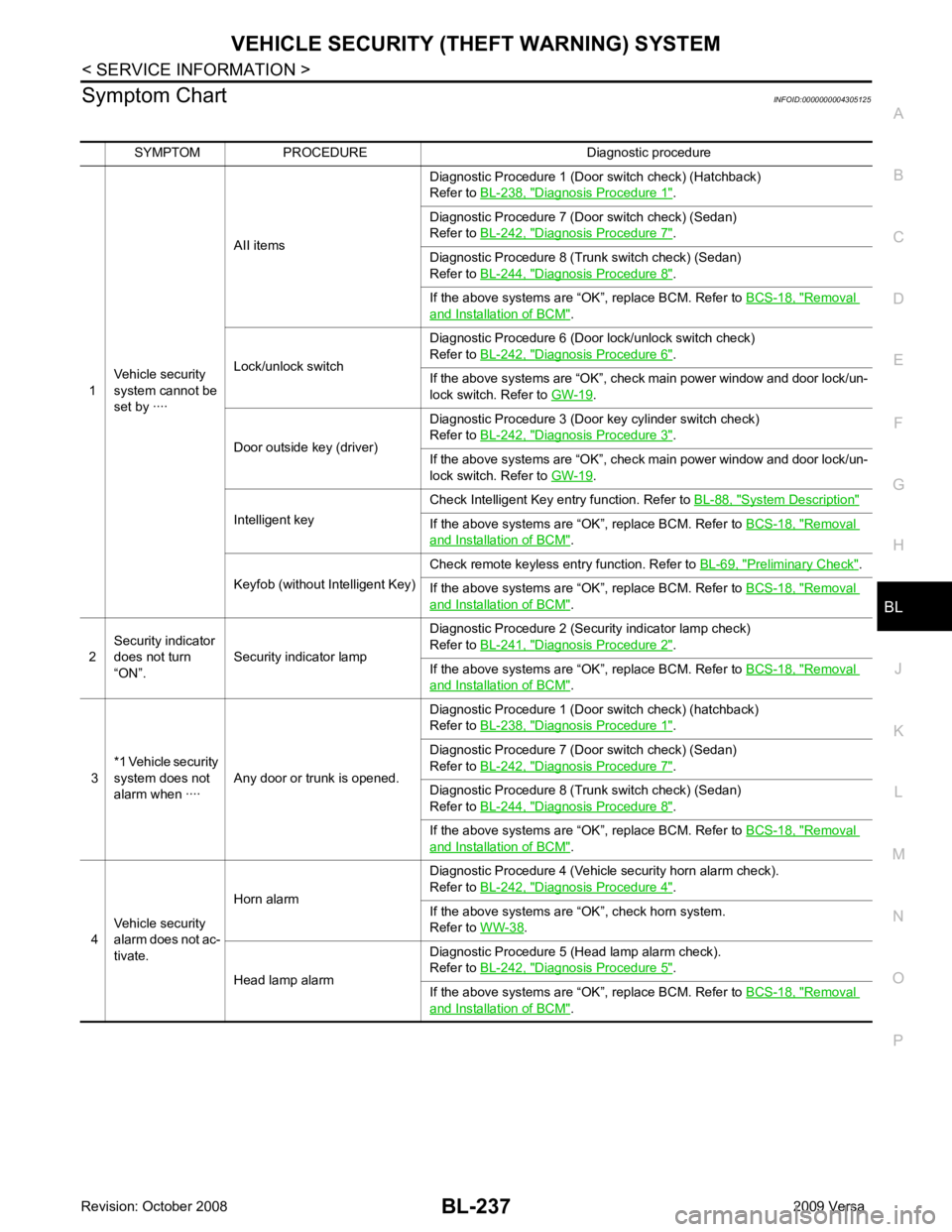
Symptom Chart
INFOID:0000000004305125
SYMPTOM PROCEDURE Diagnostic procedure
1 Vehicle security
system cannot be
set by ···· AII items
Diagnostic Procedure 1 (Door switch check) (Hatchback)
Refer to BL-238, " Diagnosis Procedure 1 " .
Diagnostic Procedure 7 (Door switch check) (Sedan)
Refer to BL-242, " Diagnosis Procedure 7 " .
Diagnostic Procedure 8 (Trunk switch check) (Sedan)
Refer to BL-244, " Diagnosis Procedure 8 " .
If the above systems are “OK”, replace BCM. Refer to BCS-18, " Removal
and Installation of BCM " .
Lock/unlock switch Diagnostic Procedure 6 (Door lock/unlock switch check)
Refer to BL-242, " Diagnosis Procedure 6 " .
If the above systems are “OK”, check main power window and door lock/un-
lock switch. Refer to GW-19 .
Door outside key (driver) Diagnostic Procedure 3 (Door key cylinder switch check)
Refer to BL-242, " Diagnosis Procedure 3 " .
If the above systems are “OK”, check main power window and door lock/un-
lock switch. Refer to GW-19 .
Intelligent key Check Intelligent Key entry function. Refer to
BL-88, " System Description "
If the above systems are “OK”, replace BCM. Refer to
BCS-18, " Removal
and Installation of BCM " .
Keyfob (without Intelligent Key) Check remote keyless entry function. Refer to
BL-69, " Preliminary Check " .
If the above systems are “OK”, replace BCM. Refer to BCS-18, " Removal
and Installation of BCM " .
2 Security indicator
does not turn
“ON”. Security indicator lamp Diagnostic Procedure 2 (Security indicator lamp check)
Refer to BL-241, " Diagnosis Procedure 2 " .
If the above systems are “OK”, replace BCM. Refer to BCS-18, " Removal
and Installation of BCM " .
3 *1 Vehicle security
system does not
alarm when ···· Any door or trunk is opened. Diagnostic Procedure 1 (Door switch check) (hatchback)
Refer to BL-238, " Diagnosis Procedure 1 " .
Diagnostic Procedure 7 (Door switch check) (Sedan)
Refer to BL-242, " Diagnosis Procedure 7 " .
Diagnostic Procedure 8 (Trunk switch check) (Sedan)
Refer to BL-244, " Diagnosis Procedure 8 " .
If the above systems are “OK”, replace BCM. Refer to BCS-18, " Removal
and Installation of BCM " .
4 Vehicle security
alarm does not ac-
tivate. Horn alarm
Diagnostic Procedure 4 (Vehicle security horn alarm check).
Refer to BL-242, " Diagnosis Procedure 4 " .
If the above systems are “OK”, check horn system.
Refer to WW-38 .
Head lamp alarm Diagnostic Procedure 5 (Head lamp alarm check).
Refer to BL-242, " Diagnosis Procedure 5 " .
If the above systems are “OK”, replace BCM. Refer to BCS-18, " Removal
and Installation of BCM " .
Page 699 of 4331
BL-238< SERVICE INFORMATION >
VEHICLE SECURITY (T
HEFT WARNING) SYSTEM
*1 : Make sure the system is in the armed phase.
Diagnosis Procedure 1 INFOID:0000000004305126
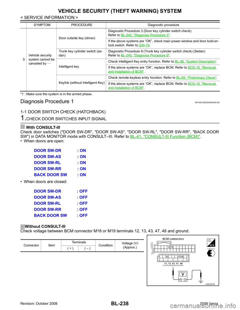
1-1 DOOR SWITCH CHECK (HATCHBACK) 1.
CHECK DOOR SWITCHES INPUT SIGNAL
With CONSULT-III
Check door switches ("DOOR SW-DR", "DOOR SW-AS", "DOOR SW-RL", "DOOR SW-RR", "BACK DOOR
SW") in DATA MONITOR mode with CONSULT–III. Refer to BL-41, " CONSULT-III Function (BCM) " .
• When doors are open:
• When doors are closed:
Without CONSULT-III
Check voltage between BCM connector M18 or M19 terminals 12, 13, 43, 47, 48 and ground.
5
Vehicle security
system cannot be
canceled by ···· Door outside key (driver)
Diagnostic Procedure 3 (Door key cylinder switch check).
Refer to BL-242, " Diagnosis Procedure 3 " .
If the above systems are “OK”, check main power window and door lock/un-
lock switch. Refer to GW-19 .
Trunk key cylinder switch (se-
dan) Diagnostic Procedure 9 (Trunk key cylinder switch check) (Sedan)
Refer to BL-245, " Diagnosis Procedure 9 " .
Intelligent key Check Intelligent Key entry function. Refer to
BL-88, " System Description "
If the above systems are “OK”, replace BCM. Refer to
BCS-18, " Removal
and Installation of BCM " .
Keyfob (without Intelligent Key) Check remote keyless entry function. Refer to
BL-69, " Preliminary Check " .
If the above systems are “OK”, replace BCM. Refer to BCS-18, " Removal
and Installation of BCM " .
SYMPTOM PROCEDURE Diagnostic procedure DOOR SW-DR : ON
DOOR SW-AS : ON
DOOR SW-RL : ON
DOOR SW-RR : ON
BACK DOOR SW : ON
DOOR SW-DR : OFF
DOOR SW-AS : OFF
DOOR SW-RL : OFF
DOOR SW-RR : OFF
BACK DOOR SW : OFF Connector Item
Terminals
ConditionVoltage (V)
(Approx.)
( + ) ( – ) LIIA1041E
Page 714 of 4331
NATS (NISSAN ANTI-THEFT SYSTEM)
BL-253
< SERVICE INFORMATION >
C
D E
F
G H
J
K L
M A
B BL
N
O P
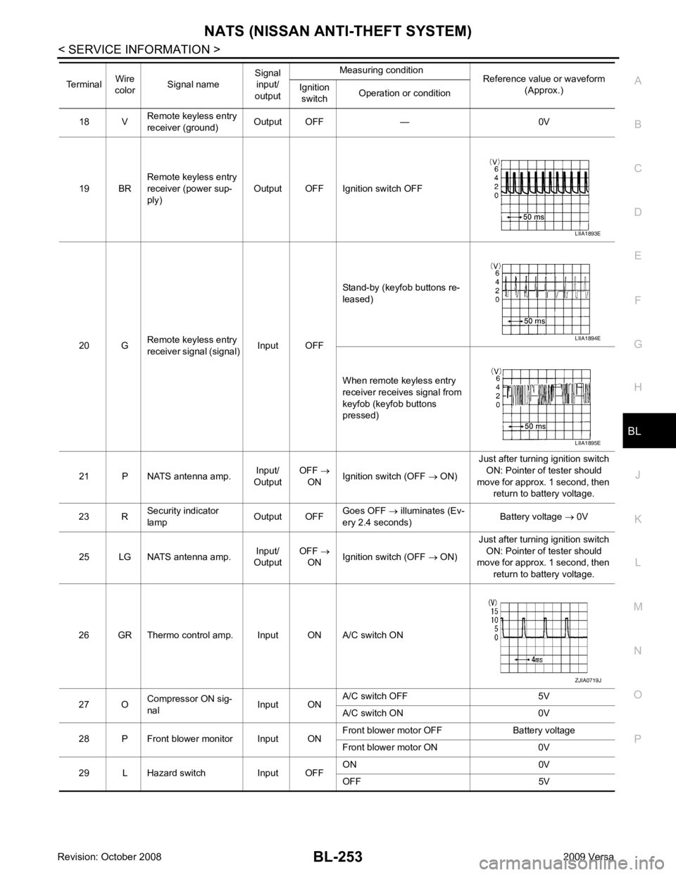
18 V
Remote keyless entry
receiver (ground) Output OFF — 0V
19 BR Remote keyless entry
receiver (power sup-
ply) Output OFF Ignition switch OFF
20 G Remote keyless entry
receiver signal (signal) Input OFFStand-by (keyfob buttons re-
leased)
When remote keyless entry
receiver receives signal from
keyfob (keyfob buttons
pressed)
21 P NATS antenna amp. Input/
Output OFF
→
ON Ignition switch (OFF
→ ON) Just after turning ignition switch
ON: Pointer of tester should
move for approx. 1 second, then return to battery voltage.
23 R Security indicator
lamp Output OFFGoes OFF
→ illuminates (Ev-
ery 2.4 seconds) Battery voltage
→ 0V
25 LG NATS antenna amp. Input/
Output OFF
→
ON Ignition switch (OFF
→ ON) Just after turning ignition switch
ON: Pointer of tester should
move for approx. 1 second, then
return to battery voltage.
26 GR Thermo control amp. Input ON A/C switch ON
27 O Compressor ON sig-
nal Input ONA/C switch OFF 5V
A/C switch ON 0V
28 P Front blower monitor Input ON Front blower motor OFF Battery voltage
Front blower motor ON 0V
29 L Hazard switch Input OFF ON 0V
OFF 5V
Terminal
Wire
color Signal name Signal
input/
output Measuring condition
Reference value or waveform
(Approx.)
Ignition
switch Operation or condition LIIA1893E
LIIA1894E
LIIA1895E
ZJIA0719J