Page 3721 of 4331
LT
N
O P
BULB SPECIFICATIONS
Headlamp INFOID:0000000004306645
Exterior Lamp INFOID:0000000004306646
Interior Lamp/Illumination INFOID:0000000004306647
* Always check with the parts department for the latest parts information. Item Wattage (W)
High/Low (Halogen type) 60/55Item Wattage (W)
Front combination lamp Turn signal lamp 21 (amber)
Parking (clearance) lamp 5
Rear combination lamp Stop/Tail lamp 21/5
Turn signal lamp 21 (amber)
Back-up lamp 21
Front fog lamp 35 (H8)
License plate lamp 5
High-mounted stop lamp Hatchback LED
Sedan, rear window 18
Sedan, rear spoiler LED Item Wattage (W)
Glove box lamp 1.4
Map lamp 8
Room lamp 8
Luggage room lamp (Hatchback) 5
Trunk room lamp (Sedan) 5
Vanity mirror lamp *
Page 3780 of 4331

MA
N
O P
CHASSIS AND BODY MAINTENANCE
IN-CABIN MICROFILTER
IN-CABIN MICROFILTER : Removal and Installation INFOID:0000000004683699
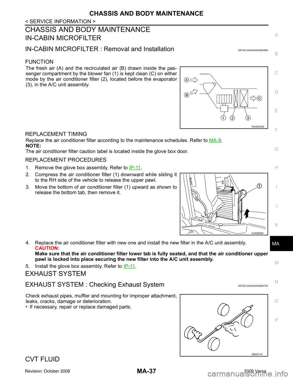
FUNCTION The fresh air (A) and the recirculated air (B) drawn inside the pas-
senger compartment by the blower fan (1) is kept clean (C) on either
mode by the air conditioner filter (2), located before the evaporator
(3), in the A/C unit assembly.
REPLACEMENT TIMING Replace the air conditioner filter according to the maintenance schedules. Refer to MA-9 .
NOTE:
The air conditioner filter caution label is located inside the glove box door.
REPLACEMENT PROCEDURES 1. Remove the glove box assembly. Refer to IP-11 .
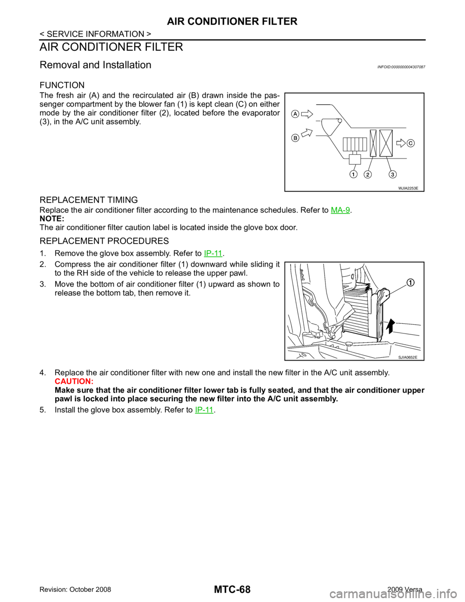
2. Compress the air conditioner filter (1) downward while sliding it to the RH side of the vehicle to release the upper pawl.
3. Move the bottom of air conditioner filter (1) upward as shown to
release the bottom tab, then remove it.
4. Replace the air conditioner filter with new one and in stall the new filter in the A/C unit assembly.
CAUTION:
Make sure that the air cond itioner filter lower tab is fully seated , and that the air conditioner upper
pawl is locked into place securing the new filter into the A/C unit assembly.
5. Install the glove box assembly. Refer to IP-11 .
EXHAUST SYSTEM
EXHAUST SYSTEM : Chec king Exhaust System INFOID:0000000004683700
Check exhaust pipes, muffler and mounting for improper attachment,
leaks, cracks, damage or deterioration.
• If necessary, repair or replace damaged parts.
CVT FLUID SMA211A
Page 3950 of 4331
MTC
N
O P
MODE DOOR
Mode Door Cable Adjustment INFOID:0000000004307084
1. Remove glove box assembly and instrument lower cover (RH). Refer to IP-11 .
2. Remove outer cable of mode door cable (1) from clamp (A).
3. Set mode control dial to VENT position.
4. Push main link (2) in the direction shown by the arrow, and then carefully pull outer cable to controller side, and install clamp (A).
5. Operate mode control dial to insure that inner cable moves smoothly.
CAUTION:
When clamping the outer cab le, do not move the inner
cable.
6. Turn mode control dial to each position.
7. Confirm that discharge air comes out accord ing to the air distribution table. Refer to MTC-20, " Discharge
Air Flow " .
Page 3953 of 4331

MTC-68< SERVICE INFORMATION >
AIR CONDITIONER FILTER
AIR CONDITIONER FILTER
Removal and Installation INFOID:0000000004307087
FUNCTION
The fresh air (A) and the recirculated air (B) drawn inside the pas-
senger compartment by the blower fan (1) is kept clean (C) on either
mode by the air conditioner filter (2), located before the evaporator
(3), in the A/C unit assembly.
REPLACEMENT TIMING
Replace the air conditioner filter accord ing to the maintenance schedules. Refer to MA-9 .
NOTE:
The air conditioner filter caution label is located inside the glove box door.
REPLACEMENT PROCEDURES
1. Remove the glove box assembly. Refer to IP-11 .
2. Compress the air conditioner filter (1) downward while sliding it to the RH side of the vehicle to release the upper pawl.
3. Move the bottom of air conditioner filter (1) upward as shown to release the bottom tab, then remove it.
4. Replace the air conditioner filter with new one and install the new filter in the A/C unit assembly. CAUTION:
Make sure that the air conditioner filter lower tab is fully seated, and that the air conditioner upper
pawl is locked into place securing the ne w filter into the A/C unit assembly.
5. Install the glove box assembly. Refer to IP-11 . WJIA2253E
SJIA0652E
Page 4274 of 4331

WT
N
O P
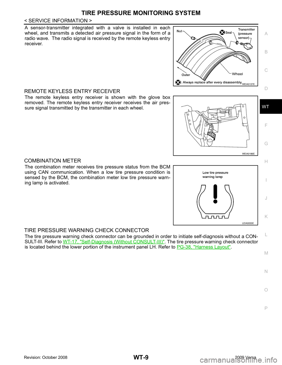
A sensor-transmitter integrated with a valve is installed in each
wheel, and transmits a detected air pressure signal in the form of a
radio wave. The radio signal is received by the remote keyless entry
receiver.
REMOTE KEYLESS ENTRY RECEIVER The remote keyless entry receiver is shown with the glove box
removed. The remote keyless entry receiver receives the air pres-
sure signal transmitted by the transmitter in each wheel.
COMBINATION METER The combination meter receives tire pressure status from the BCM
using CAN communication. When a low tire pressure condition is
sensed by the BCM, the combination meter low tire pressure warn-
ing lamp is activated.
TIRE PRESSURE WARNING CHECK CONNECTOR The tire pressure warning check connector can be grounded in order to initiate self-diagnosis without a CON-
SULT-III. Refer to WT-17, " Self-Diagnosis (Without CONSULT-III) " . The tire pressure warning check connector
is located behind the lower portion of the instrument panel LH. Refer to PG-38, " Harness Layout " . WEIA0186E
LEIA0055E
Page 4295 of 4331

WW
N
O P
FRONT WIPER AND WASHER SYSTEM
Component Parts and Har ness Connector Location INFOID:0000000004306904
System Description INFOID:0000000004306905
• Front wiper relays (front wiper relay, front wiper hi gh relay) are located in the IPDM E/R (intelligent power
distribution module engine room).
• Wiper switch (combination switch) is composed of a combination of 5 output terminals and 5 input terminals.
Terminal combination status is read by BCM (body control module) when switch is turned ON.
• BCM controls front wiper LO, HI, and INT (intermittent) operation.
• IPDM E/R operates wiper motor accordi ng to CAN communication signals from BCM.
OUTLINE
Power is supplied at all times
• to ignition relay, located in IPDM E/R, from battery directly,
• through 40A fusible link (letter g, located in fuse and fusible link box)
• to BCM terminal 70,
• through 30A fuse (No. 39, located in IPDM E/R)
• to front wiper relay located in IPDM E/R
• through 15A fuse (No. 52, located in IPDM E/R), and
• through 20A fuse (No. 53, located in IPDM E/R)
• to CPU located in IPDM E/R.
When ignition switch is in ON or START position, power is supplied
• through ignition relay (located in IPDM E/R)
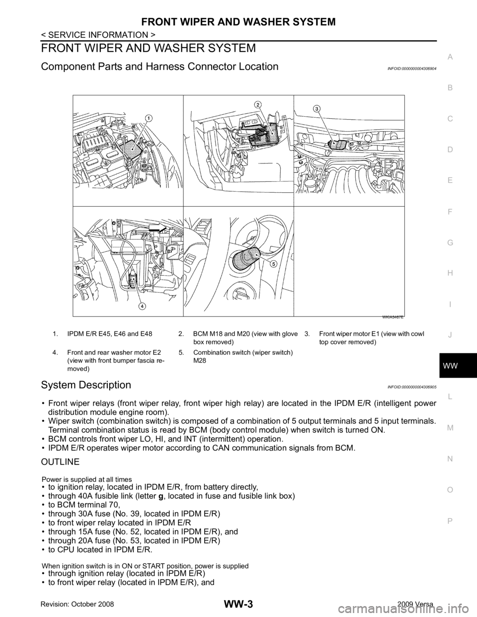
• to front wiper relay (located in IPDM E/R), and 1. IPDM E/R E45, E46 and E48 2. BCM M18 and M20 (view with glove
box removed)3. Front wiper motor E1
(view with cowl
top cover removed)
4. Front and rear washer motor E2 (view with front bumper fascia re-
moved) 5. Combination switch (wiper switch)
M28
Page:
< prev 1-8 9-16 17-24