2009 NISSAN TIIDA lock
[x] Cancel search: lockPage 536 of 4331
REMOTE KEYLESS ENTRY SYSTEM
BL-75
< SERVICE INFORMATION >
C
D E
F
G H
J
K L
M A
B BL
N
O P
• When doors are closed:
Without CONSULT-III
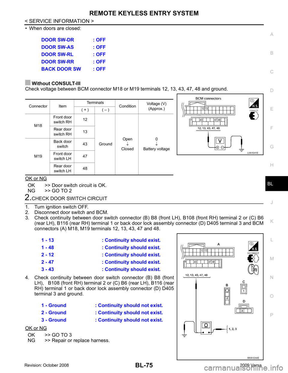
Check voltage between BCM connector M18 or M19 terminals 12, 13, 43, 47, 48 and ground.
OK or NG OK >> Door switch circuit is OK.
NG >> GO TO 2 2.
CHECK DOOR SWITCH CIRCUIT
1. Turn ignition switch OFF.
2. Disconnect door switch and BCM.
3. Check continuity between door switch connector (B) B8 (front LH), B108 (front RH) terminal 2 or (C) B6
(rear LH), B116 (rear RH) terminal 1 or back door lock assembly connector (D) D405 terminal 3 and BCM
connectors (A) M18, M19 te rminals 12, 13, 43, 47 and 48.
4. Check continuity between door switch connector (B) B8 (front LH), B108 (front RH) terminal 2 or (C) B6 (rear LH), B116 (rear
RH) terminal 1 or back door lo ck assembly connector (D) D405
terminal 3 and ground.
OK or NG OK >> GO TO 3
NG >> Repair or replace harness. DOOR SW-DR : OFF
DOOR SW-AS : OFF
DOOR SW-RL : OFF
DOOR SW-RR : OFF
BACK DOOR SW : OFF
Connector Item Terminals
ConditionVoltage (V)
(Approx.)
( + ) ( – )
M18 Front door
switch RH 12
Ground Open
↓
Closed 0
↓
Battery voltage
Rear door
switch RH 13
M19 Back door
switch 43
Front door switch LH 47
Rear door switch LH 48 LIIA1041E
1 - 13 : Continuity should exist.
1 - 48 : Continuity should exist.
2 - 12 : Continuity should exist.
2 - 47 : Continuity should exist.
3 - 43 : Continuity should exist.
1 - Ground : Continuity should not exist.
2 - Ground : Continuity should not exist.
3 - Ground : Continuity should not exist. WIIA1244E
Page 537 of 4331
BL-76< SERVICE INFORMATION >
REMOTE KEYLESS ENTRY SYSTEM3.
CHECK DOOR SWITCHES
FRONT AND REAR DOORS
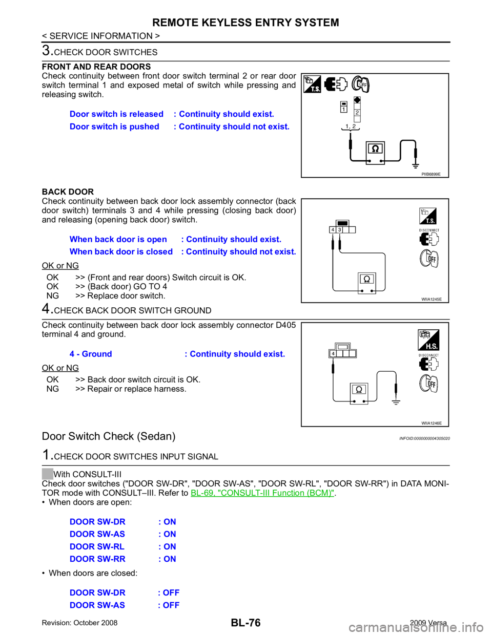
Check continuity between front door switch terminal 2 or rear door
switch terminal 1 and exposed metal of switch while pressing and
releasing switch.
BACK DOOR
Check continuity between back door lock assembly connector (back
door switch) terminals 3 and 4 while pressing (closing back door)
and releasing (opening back door) switch.
OK or NG OK >> (Front and rear doors) Switch circuit is OK.
OK >> (Back door) GO TO 4
NG >> Replace door switch. 4.
CHECK BACK DOOR SWITCH GROUND
Check continuity between back door lock assembly connector D405
terminal 4 and ground.
OK or NG OK >> Back door switch circuit is OK.
NG >> Repair or replace harness.
Door Switch Check (Sedan) INFOID:00000000043050201.
CHECK DOOR SWITCHES INPUT SIGNAL
With CONSULT-III
Check door switches ("DOOR SW-DR", "DOOR SW-AS" , "DOOR SW-RL", "DOOR SW-RR") in DATA MONI-
TOR mode with CONSULT–III. Refer to BL-69, " CONSULT-III Function (BCM) " .
• When doors are open:
• When doors are closed: Door switch is released :
Continuity should exist.
Door switch is pushed : Co ntinuity should not exist. PIIB6899E
When back door is open :
Continuity should exist.
When back door is closed : Co ntinuity should not exist. WIIA1245E
4 - Ground : Continuity should exist.
WIIA1246E
DOOR SW-DR : ON
DOOR SW-AS : ON
DOOR SW-RL : ON
DOOR SW-RR : ON
DOOR SW-DR : OFF
DOOR SW-AS : OFF
Page 539 of 4331
BL-78< SERVICE INFORMATION >
REMOTE KEYLESS ENTRY SYSTEM
Key Switch (I nsert) Check INFOID:00000000043050211.
CHECK KEY SWITCH INPUT SIGNAL
With CONSULT-III
Check key switch "KEY ON SW" in DATA MONITOR mode with CONSULT–III. Refer to BL-41, " CONSULT-III
Function (BCM) " .
• When key is inserted into ignition key cylinder:
• When key is removed from ignition key cylinder:
Without CONSULT-III
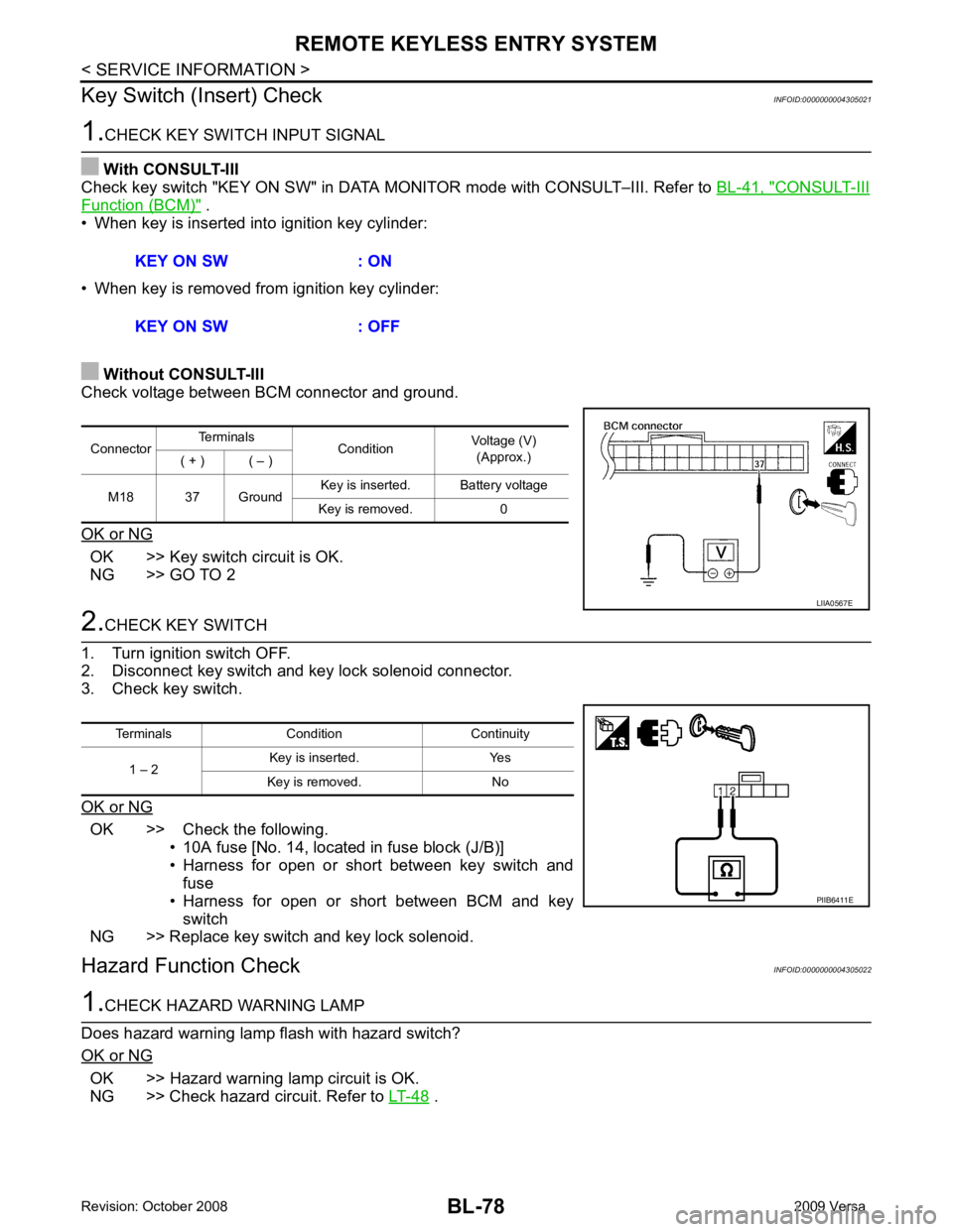
Check voltage between BCM connector and ground.
OK or NG OK >> Key switch circuit is OK.
NG >> GO TO 2 2.
CHECK KEY SWITCH
1. Turn ignition switch OFF.
2. Disconnect key switch and key lock solenoid connector.
3. Check key switch.
OK or NG OK >> Check the following.
• 10A fuse [No. 14, located in fuse block (J/B)]
• Harness for open or short between key switch and fuse
• Harness for open or short between BCM and key switch
NG >> Replace key switch and key lock solenoid.
Hazard Function Check INFOID:00000000043050221.
CHECK HAZARD WARNING LAMP
Does hazard warning lamp flash with hazard switch?
OK or NG OK >> Hazard warning lamp circuit is OK.
NG >> Check hazard circuit. Refer to LT-48 .
KEY ON SW : ON
KEY ON SW : OFF Connector
Terminals
ConditionVoltage (V)
(Approx.)
( + ) ( – )
M18 37 Ground Key is inserted. Battery voltage
Key is removed. 0 LIIA0567E
Terminals Condition Continuity
1 – 2 Key is inserted. Yes
Key is removed. No PIIB6411E
Page 543 of 4331
OK >> Replace remote keyless entry receiver. Refer to
BL-85, " Removal and Installation of Remote Key-
less Entry Receiver " .
NG >> Repair or replace harness.
Keyfob Function (Lock) Check INFOID:0000000004305026OK >> Keyfob is OK.
NG >> Replace keyfob.
Keyfob Function (Unlock) Check INFOID:0000000004305027OK >> Keyfob is OK.
NG >> Replace keyfob.
ID Code Entry Procedure INFOID:0000000004305028
KEYFOB ID SET UP WITH CONSULT-III
NOTE:
• If a keyfob is lost, the ID code of the lost keyfob must be erased to prevent unauthorized use. A spe-
cific ID code can be erased with CONSULT-III. Ho wever, when the ID code of a lost keyfob is not
known, all controller ID codes should be erased. After all ID codes are erased, the ID codes of all
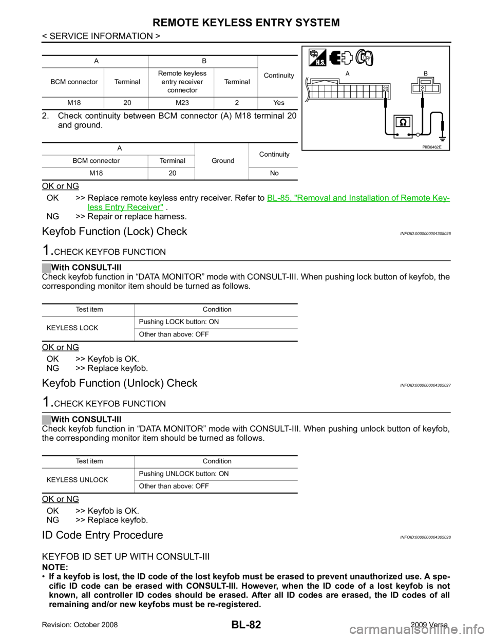
remaining and/or new keyfobs must be re-registered. A B
Continuity
BCM connector Terminal Remote keyless
entry receiver
connector Terminal
M18 20 M23 2 Yes
A GroundContinuity
BCM connector Terminal
M18 20 No Test item Condition
KEYLESS UNLOCK Pushing UNLOCK button: ON
Other than above: OFF
Page 550 of 4331
BL
N
O P
Operation Description
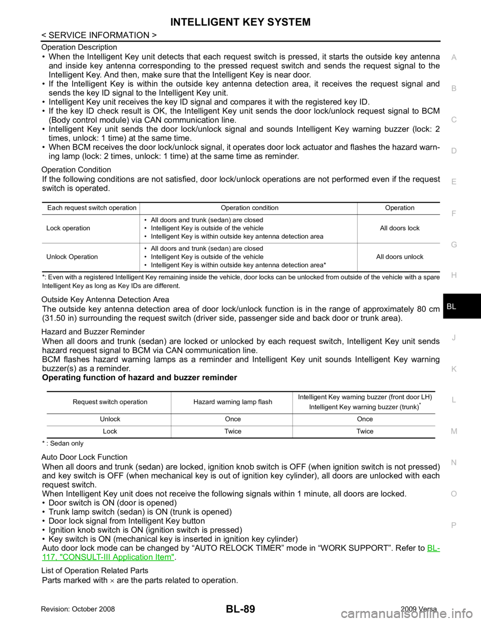
• When the Intelligent Key unit detects that each request sw itch is pressed, it starts the outside key antenna
and inside key antenna corresponding to the pressed r equest switch and sends the request signal to the
Intelligent Key. And then, make sure that the Intelligent Key is near door.
• If the Intelligent Key is within the outside key ant enna detection area, it receives the request signal and
sends the key ID signal to the Intelligent Key unit.
• Intelligent Key unit receives the key ID signal and compares it with the registered key ID.
• If the key ID check result is OK, the Intelligent Ke y unit sends the door lock/unlock request signal to BCM
(Body control module) via CAN communication line.
• Intelligent Key unit sends the door lock/unlock signal and sounds Intelligent Key warning buzzer (lock: 2 times, unlock: 1 time) at the same time.
• When BCM receives the door lock/unlock signal, it oper ates door lock actuator and flashes the hazard warn-
ing lamp (lock: 2 times, unlock: 1 time) at the same time as reminder.
Operation Condition If the following conditions are not satisfied, door lo ck/unlock operations are not performed even if the request
switch is operated.
*: Even with a registered Intelligent Key remaining inside the vehicle, door locks can be unlocked from outside of the vehicle with a spare
Intelligent Key as long as Key IDs are different.
Outside Key Antenna Detection Area The outside key antenna detection area of door lock/unloc k function is in the range of approximately 80 cm
(31.50 in) surrounding the request switch (driver side, passenger side and back door or trunk area).
Hazard and Buzzer Reminder When all doors and trunk (sedan) are locked or unlocked by each request switch, Intelligent Key unit sends
hazard request signal to BCM via CAN communication line.
BCM flashes hazard warning lamps as a reminder and Intelligent Key unit sounds Intelligent Key warning
buzzer(s) as a reminder.
Operating function of hazard and buzzer reminder
* : Sedan only
Auto Door Lock Function When all doors and trunk (sedan) are locked, ignition knob sw itch is OFF (when ignition switch is not pressed)
and key switch is OFF (when mechanical key is out of ignition key cylinder), all doors are unlocked with each
request switch.
When Intelligent Key unit does not receive the following signals within 1 minute, all doors are locked.
• Door switch is ON (door is opened)
• Trunk lamp switch (sedan) is ON (trunk is opened)
• Door lock signal from Intelligent Key button
• Ignition knob switch is ON (ignition switch is pressed)
• Key switch is ON (mechanical key is inserted in ignition key cylinder)
Auto door lock mode can be changed by “AUTO RELOCK TIMER” mode in “WORK SUPPORT”. Refer to BL-117, " CONSULT-III Application Item " .
List of Operation Related Parts Parts marked with × are the parts related to operation.
Each request switch operation Operation condition Operation
Lock operation • All doors and trunk (sedan) are closed
• Intelligent Key is outside of the vehicle
• Intelligent Key is within outside key antenna detection area All doors lock
Unlock Operation • All doors and trunk (sedan) are closed
• Intelligent Key is outside of the vehicle
• Intelligent Key is within outside key antenna detection area* All doors unlockRequest switch operation Hazard warning lamp flash
Intelligent Key warning buzzer (front door LH)
Intelligent Key warning buzzer (trunk) *
Unlock Once Once Lock Twice Twice
Page 551 of 4331

Key reminder functionsIntelligent Key
Door switch
Unlock sensor
Door lock actuator
Inside key antenna
Intelligent Key warning buzzer(s)
Intelligent Key unit
CAN communication system
BCM
Any door open to close × × × × × × × × ×
Page 552 of 4331
BL
N
O P
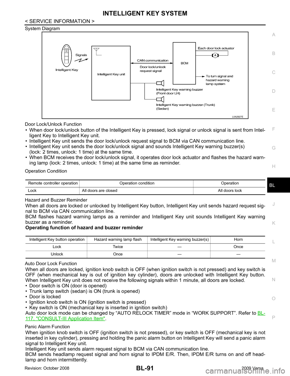
System Diagram
Door Lock/Unlock Function • When door lock/unlock button of the Intelligent Key is pr essed, lock signal or unlock signal is sent from Intel-
ligent Key to Intelligent Key unit.
• Intelligent Key unit sends the door lock/unlock request signal to BCM via CAN communication line.
• Intelligent Key unit sends the door lock/unlock signal and sounds Intelligent Key warning buzzer(s) (lock: 2 times, unlock: 1 time) at the same time.
• When BCM receives the door lock/unlock signal, it oper ates door lock actuator and flashes the hazard warn-
ing lamp (lock: 2 times, unlock: 1 time) at the same time as reminder.
Operation Condition
Hazard and Buzzer Reminder When all doors are locked or unlocked by Intelligent Ke y button, Intelligent Key unit sends hazard request sig-
nal to BCM via CAN communication line.
BCM flashes hazard warning lamps as a reminder and Intelligent Key unit sounds Intelligent Key warning
buzzer as a reminder.
Operating function of hazard and buzzer reminder
Auto Door Lock Function When all doors are locked, ignition knob switch is OFF (when ignition switch is not pressed) and key switch is
OFF (when mechanical key is out of ignition key cyli nder), doors are unlocked with Intelligent Key button.
When Intelligent Key unit does not receive the following signals within 1 minute, all doors are locked.
• Door switch is ON (door is opened)
• Trunk lamp switch (sedan) is ON (trunk is opened)
• Door is locked
• Ignition knob switch is ON (ignition switch is pressed)
• Key switch is ON (mechanical key is inserted in ignition switch)
Auto door lock mode can be changed by “AUTO RELOCK TIMER” mode in “WORK SUPPORT”. Refer to BL-117, " CONSULT-III Application Item " .
Panic Alarm Function When ignition knob switch is OFF (ignition switch is not pressed), or key switch is OFF (mechanical key is not
inserted in key cylinder), pressing and holding the panic alarm button on Intelligent Key will send a panic alarm
signal to Intelligent Key unit.
Intelligent Key unit sends alarm request signal to BCM via CAN communication line.
BCM sends headlamp request signal and horn signal to IPDM E/R. Then, IPDM E/R turns on and off head-
lamp and horn intermittently. Intelligent Key button operation Hazard warning lamp flash Intelligent Key warning buzzer(s) Horn
Lock Twice — Once
Unlock Once — —
Page 553 of 4331
CONSULT-III Application Item " .
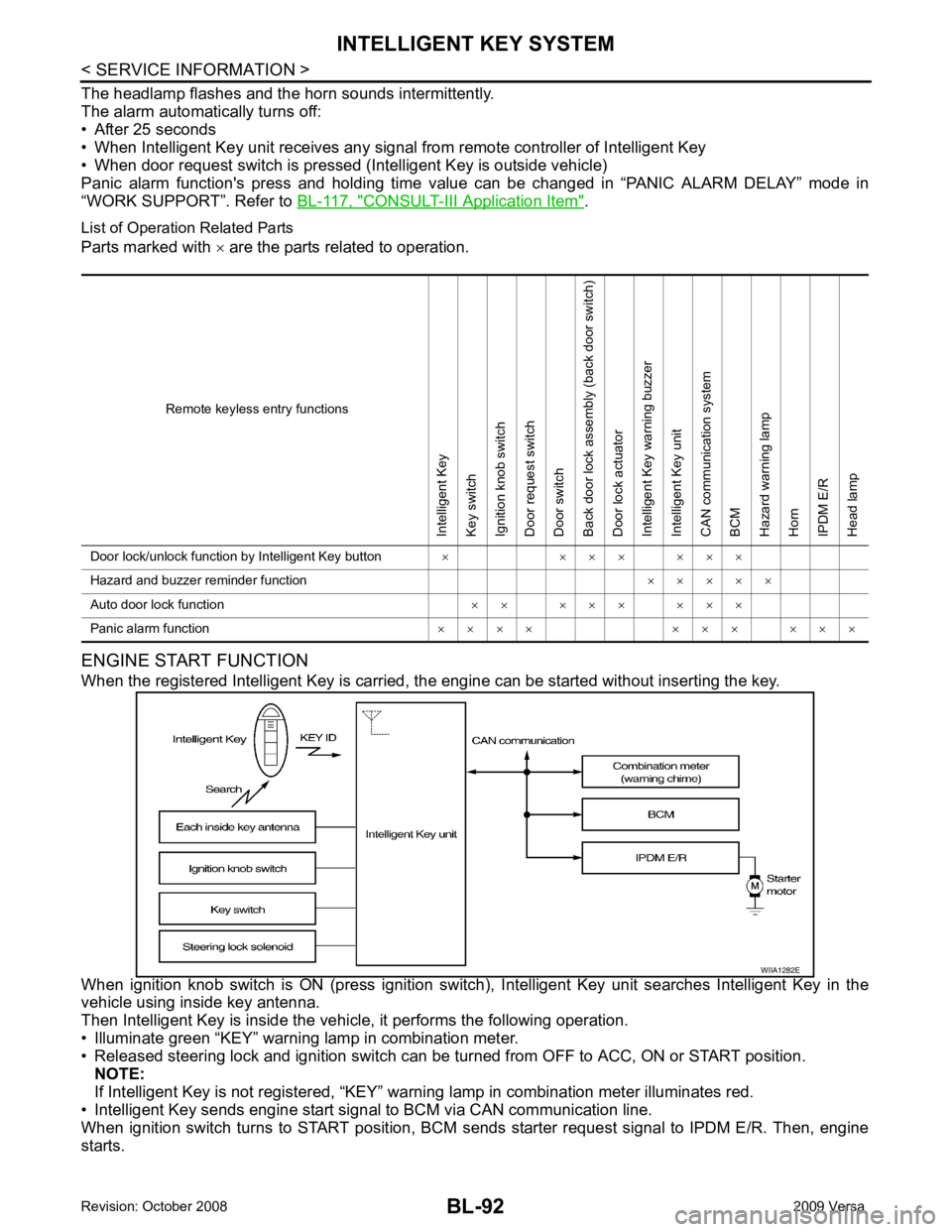
List of Operation Related Parts
Parts marked with × are the parts related to operation.
ENGINE START FUNCTION
When the registered Intelligent Key is carried, the engine can be started without inserting the key.
When ignition knob switch is ON (press ignition switch ), Intelligent Key unit searches Intelligent Key in the
vehicle using inside key antenna.
Then Intelligent Key is inside the vehicle, it performs the following operation.
• Illuminate green “KEY” warning lamp in combination meter.
• Released steering lock and ignition switch can be tu rned from OFF to ACC, ON or START position.
NOTE:
If Intelligent Key is not registered, “KEY” warni ng lamp in combination meter illuminates red.
• Intelligent Key sends engine start signal to BCM via CAN communication line.
When ignition switch turns to START position, BCM s ends starter request signal to IPDM E/R. Then, engine
starts. Remote keyless entry functionsIntelligent Key
Key switch
Ignition knob switch
Door request switch
Door switch
Back door lock assembly (back door switch)
Door lock actuator
Intelligent Key warning buzzer
Intelligent Key unit
CAN communication system
BCM
Hazard warning lamp
Horn
IPDM E/R
Head lamp
Door lock/unlock function by Intelligent Key button × × × × × × ×
Hazard and buzzer reminder function × × × × ×
Auto door lock function × × × × × × × ×
Panic alarm function × × × × × × × × × ×