2009 NISSAN TIIDA heater
[x] Cancel search: heaterPage 2847 of 4331
![NISSAN TIIDA 2009 Service Repair Manual DTC P2A00 A/F SENSOR 1
EC-1491
< SERVICE INFOMATION >
[MR TYPE 2] C
D E
F
G H
I
J
K L
M A EC
NP
O
Do not use ECM ground terminals wh
en measuring input/output voltage. Doing so may result in dam-
age NISSAN TIIDA 2009 Service Repair Manual DTC P2A00 A/F SENSOR 1
EC-1491
< SERVICE INFOMATION >
[MR TYPE 2] C
D E
F
G H
I
J
K L
M A EC
NP
O
Do not use ECM ground terminals wh
en measuring input/output voltage. Doing so may result in dam-
age](/manual-img/5/57398/w960_57398-2846.png)
DTC P2A00 A/F SENSOR 1
EC-1491
< SERVICE INFOMATION >
[MR TYPE 2] C
D E
F
G H
I
J
K L
M A EC
NP
O
Do not use ECM ground terminals wh
en measuring input/output voltage. Doing so may result in dam-
age to the ECM's transistor. Use a ground ot her than ECM terminals, such as the ground.
: Average voltage for pulse signal (Actual pulse signal can be confirmed by oscilloscope.)
Diagnosis Procedure INFOID:00000000045003961.
CHECK GROUND CONNECTIONS
1. Turn ignition switch OFF.
2. Loosen and retighten ground screws on the body. Refer to EC-1144, " Ground Inspection " .
OK or NG OK >> GO TO 2.
NG >> Repair or replace ground connections. 2.
RETIGHTEN AIR FUEL RATIO (A/F) SENSOR 1
Loosen and retighten the air fuel rati o (A/F) sensor 1. Refer to EM-144, " Removal and Installation " .
>> GO TO 3. 3.
CHECK FOR INTAKE AIR LEAK
1. Start engine and run it at idle.
2. Listen for an intake air leak after the mass air flow sensor.
OK or NG OK >> GO TO 4.
NG >> Repair or replace. TERMI-
NAL
NO. WIRE
COLOR ITEM CONDITION DATA (DC Voltage)
3 G A/F sensor 1 heater [Engine is running]
• Warm-up condition
• Idle speed
(More than 140 seconds after starting
engine) Approximately 2.9 - 8.8V
49 W A/F sensor 1 [Engine is running]
• Warm-up condition
• Engine speed: 2,000 rpm Approximately 1.8V
Output voltage varies with air fuel
ratio.
53 B A/F sensor 1 [Ignition switch: ON]Approximately 2.2V PBIA8148J
:
Vehicle front
1. Body ground E24 2. Engine ground F9 3. Engine ground F16
4. Body ground E15 BBIA0698E
Page 2850 of 4331
![NISSAN TIIDA 2009 Service Repair Manual EC-1494< SERVICE INFOMATION >
[MR TYPE 2]
DTC P2A00 A/F SENSOR 1
1. Start engine and warm it up to normal operating temperature.
2. Select “SELF-LEARNING CONT” in “WORK SUPPORT” mode with CON NISSAN TIIDA 2009 Service Repair Manual EC-1494< SERVICE INFOMATION >
[MR TYPE 2]
DTC P2A00 A/F SENSOR 1
1. Start engine and warm it up to normal operating temperature.
2. Select “SELF-LEARNING CONT” in “WORK SUPPORT” mode with CON](/manual-img/5/57398/w960_57398-2849.png)
EC-1494< SERVICE INFOMATION >
[MR TYPE 2]
DTC P2A00 A/F SENSOR 1
1. Start engine and warm it up to normal operating temperature.
2. Select “SELF-LEARNING CONT” in “WORK SUPPORT” mode with CONSULT-III.
3. Clear the self-learning control coefficient by touching “CLEAR”.
Without CONSULT-III
1. Start engine and warm it up to normal operating temperature.
2. Turn ignition switch OFF.
3. Disconnect mass air flow sensor harness (1) connector.
4. Restart engine and let it idle for at least 5 seconds.
5. Stop engine and reconnect mass air flow sensor harness con- nector.
6. Make sure DTC P0102 is displayed.
7. Erase the DTC memory. Refer to EC-1052, " Emission-related
Diagnostic Information " .
8. Make sure DTC P0000 is displayed.
>> GO TO 14. 14.
CONFIRM A/F ADJUSTMENT DATA
1. Turn ignition switch OFF and then ON.
2. Select “A/F ADJ-B1” in “DAT A MONITOR” mode with CONSULT-III.
3. Make sure that “0.000” is displayed on CONSULT-III screen.
>>INSPECTION END
Removal and Installation INFOID:0000000004501228
AIR FUEL RATIO SENSOR HEATER
Refer to EM-144, " Removal and Installation " . BBIA0701E
Page 2862 of 4331
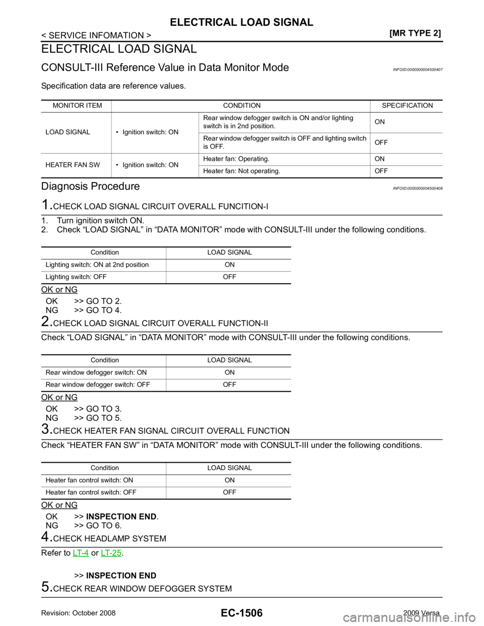
OK >> GO TO 2.
NG >> GO TO 4. OK >> GO TO 3.
NG >> GO TO 5. OK >>
INSPECTION END .
NG >> GO TO 6. or
LT-25 .
>> INSPECTION END Condition LOAD SIGNAL
Lighting switch: ON at 2nd position ON
Lighting switch: OFF OFF Condition LOAD SIGNAL
Rear window defogger switch: ON ON
Rear window defogger switch: OFF OFF Condition LOAD SIGNAL
Heater fan control switch: ON ON
Heater fan control switch: OFF OFF
Page 2891 of 4331
EC
NP
O
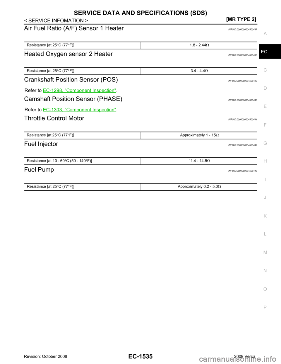
Air Fuel Ratio (A/F) Sensor 1 Heater
INFOID:0000000004500437
Heated Oxygen sensor 2 Heater INFOID:0000000004500438
Crankshaft Position Sensor (POS) INFOID:0000000004500439
Refer to EC-1298, " Component Inspection " .
Camshaft Position Sensor (PHASE) INFOID:0000000004500440
Refer to EC-1303, " Component Inspection " .
Throttle Control Motor INFOID:0000000004500441
Fuel Injector INFOID:0000000004500442
Fuel Pump INFOID:0000000004500443
Resistance [at 25
°C (77 °F)] 1.8 - 2.44 Ω
Page 3036 of 4331
EM
NP
O
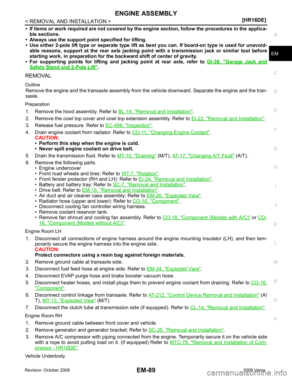
• If items or work required are not covered by the
engine section, follow the procedures in the applica-
ble sections.
• Always use the support poin t specified for lifting.
• Use either 2-pole lift type or separate type lift as best you can. If board-on type is used for unavoid-
able reasons, support at the rear axle jacking point with a transmission jack or similar tool before
starting work, in prepar ation for the backward shif t of center of gravity.
• For supporting points fo r lifting and jacking point at rear axle, refer to GI-38, " Garage Jack and
Safety Stand and 2-Pole Lift " .
REMOVAL
Outline Remove the engine and the transaxle assembly from t he vehicle downward. Separate the engine and the tran-
saxle.
Preparation 1. Remove the hood assembly. Refer to BL-14, " Removal and Installation " .
2. Remove the cowl top cover and cowl top extension assembly. Refer to EI-22, " Removal and Installation " .
3. Release fuel pressure. Refer to EC-498, " Inspection " .
4. Drain engine coolant from radiator. Refer to CO-11, " Changing Engine Coolant " .
CAUTION:
• Perform this step when the engine is cold.
• Never spill engine coolant on drive belt.
5. Drain the transmission fluid. Refer to MT-10, " Draining " (M/T),
AT-17, " Changing A/T Fluid " (A/T).
6. Remove the following parts. • Engine undercover
• Front road wheels and tires: Refer to WT-7, " Rotation " .
• Front fender protector (RH and LH): Refer to EI-24, " Removal and Installation " .
• Battery and battery tray: Refer to SC-7, " Removal and Installation " .
• Drive belt: Refer to EM-15, " Removal and Installation " .
• Air duct and air cleaner case assembly: Refer to EM-26, " Exploded View " .
• Radiator hose (upper and lower): Refer to CO-16, " Component " .
• Disconnect cooling fan controller wiring harness.
• Remove coolant reservoir tank.
• Remove fan shroud and cooling fan assembly. Refer to CO-18, " Component (Models with A/C) " or
CO- 18, " Component (Models without A/C) " .
Engine Room LH 1. Disconnect all connections of engine harness around the engine mounting insulator (LH), and then tem- porarily secure the engine harness into the engine side.
CAUTION:
Protect connectors using a resin bag against foreign materials.
2. Remove ground cable at transaxle side.
3. Disconnect fuel feed hose at engine side. Refer to EM-34, " Exploded View " .
4. Disconnect EVAP purge hose and brake booster vacuum hose.
5. Disconnect heater hoses, and install plugs them to prevent engine coolant from draining. Refer to CO-16," Component " .
6. Disconnect control linkage from transaxle. Refer to AT-212, " Control Device Removal and Installation " (A/
T), MT-13, " Exploded View " (M/T).
7. Disconnect the clutch tube at tr ansmission side (if equipped). Refer to CL-14, " Removal and Installation " .
Engine Room RH 1. Remove ground cable between front cover and vehicle.
2. Remove generator and generator bracket; Refer to SC-25, " Removal and Installation " .
3. Remove A/C compressor with piping connected from t he engine. Temporarily secure it on the vehicle side
with a rope to avoid putting load on it. (if equipped) Refer to MTC-78, " Removal and Installation of Com-
pressor - HR16DE " .
Vehicle Underbody
Page 3143 of 4331
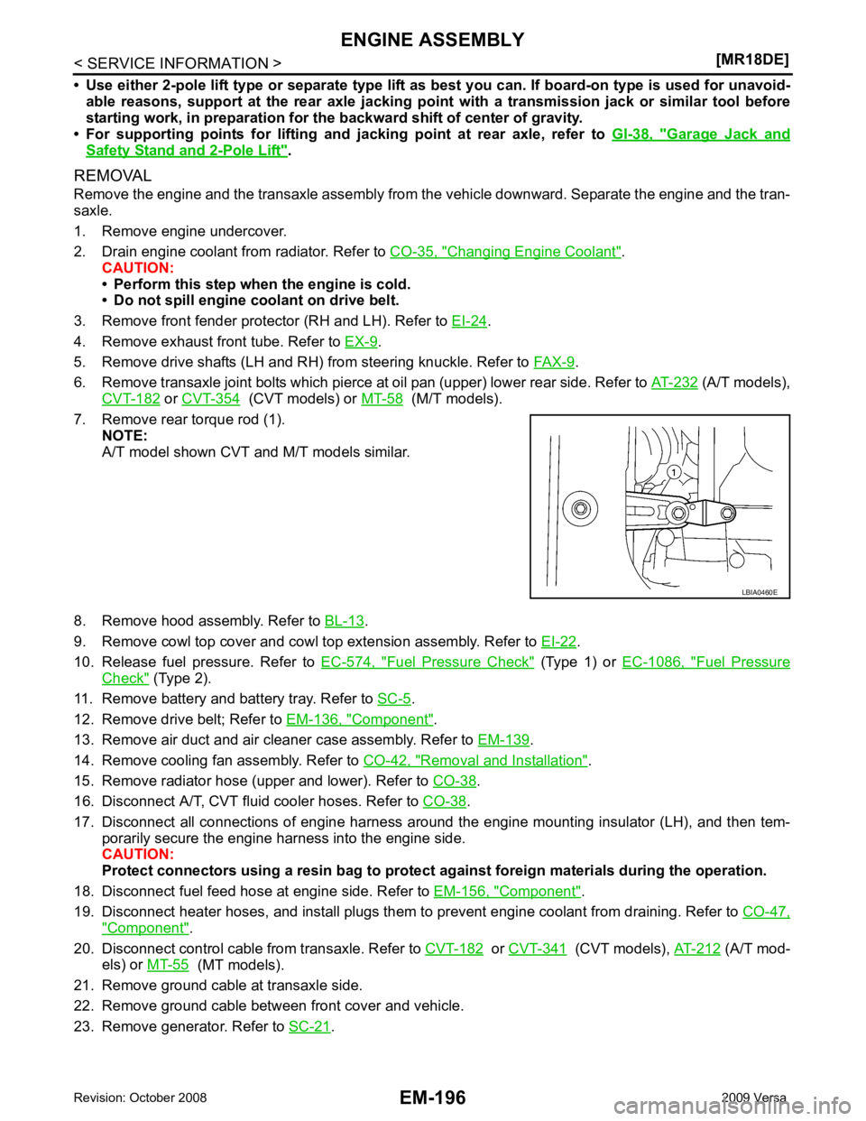
Garage Jack and
Safety Stand and 2-Pole Lift " .
REMOVAL
Remove the engine and the transaxle assembly from t he vehicle downward. Separate the engine and the tran-
saxle.
1. Remove engine undercover.
2. Drain engine coolant from radiator. Refer to CO-35, " Changing Engine Coolant " .
CAUTION:
• Perform this step when the engine is cold.
• Do not spill engine coolant on drive belt.
3. Remove front fender protector (RH and LH). Refer to EI-24 .
4. Remove exhaust front tube. Refer to EX-9 .
5. Remove drive shafts (LH and RH) from steering knuckle. Refer to FAX-9 .
6. Remove transaxle joint bolts which pierce at oil pan (upper) lower rear side. Refer to AT-232 (A/T models),
CVT-182 or
CVT-354 (CVT models) or
MT-58 (M/T models).
7. Remove rear torque rod (1). NOTE:
A/T model shown CVT and M/T models similar.
8. Remove hood assembly. Refer to BL-13 .
9. Remove cowl top cover and cowl top extension assembly. Refer to EI-22 .
10. Release fuel pressure. Refer to EC-574, " Fuel Pressure Check " (Type 1) or
EC-1086, " Fuel Pressure
Check " (Type 2).
11. Remove battery and battery tray. Refer to SC-5 .
12. Remove drive belt; Refer to EM-136, " Component " .
13. Remove air duct and air cleaner case assembly. Refer to EM-139 .
14. Remove cooling fan assembly. Refer to CO-42, " Removal and Installation " .
15. Remove radiator hose (upper and lower). Refer to CO-38 .
16. Disconnect A/T, CVT fluid cooler hoses. Refer to CO-38 .
17. Disconnect all connections of engine harness around the engine mounting insulator (LH), and then tem- porarily secure the engine harness into the engine side.
CAUTION:
Protect connectors using a resin bag to protect against foreign materials during the operation.
18. Disconnect fuel feed hose at engine side. Refer to EM-156, " Component " .
19. Disconnect heater hoses, and install plugs them to prevent engine coolant from draining. Refer to CO-47," Component " .
20. Disconnect control cable from transaxle. Refer to CVT-182 or
CVT-341 (CVT models),
AT-212 (A/T mod-
els) or MT-55 (MT models).
21. Remove ground cable at transaxle side.
22. Remove ground cable between front cover and vehicle.
23. Remove generator. Refer to SC-21 .
Page 3147 of 4331
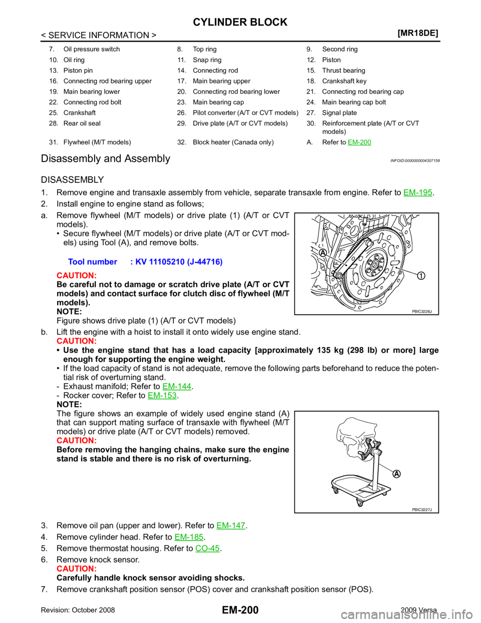
.
2. Install engine to engine stand as follows;
a. Remove flywheel (M/T models) or drive plate (1) (A/T or CVT models).
• Secure flywheel (M/T models) or drive plate (A/T or CVT mod-
els) using Tool (A), and remove bolts.
CAUTION:
Be careful not to damage or scratch drive plate (A/T or CVT
models) and contact surface for clutch disc of flywheel (M/T
models).
NOTE:
Figure shows drive plate (1) (A/T or CVT models)
b. Lift the engine with a hoist to install it onto widely use engine stand. CAUTION:
• Use the engine stand that has a load capacity [approximately 135 kg (298 lb) or more] large
enough for supporting the engine weight.
• If the load capacity of stand is not adequate, remo ve the following parts beforehand to reduce the poten-
tial risk of overturning stand.
- Exhaust manifold; Refer to EM-144 .
- Rocker cover; Refer to EM-153 .
NOTE:
The figure shows an example of widely used engine stand (A)
that can support mating surface of transaxle with flywheel (M/T
models) or drive plate (A/T or CVT models) removed.
CAUTION:
Before removing the hanging chains, make sure the engine
stand is stable and there is no risk of overturning.
3. Remove oil pan (upper and lower). Refer to EM-147 .
4. Remove cylinder head. Refer to EM-185 .
5. Remove thermostat housing. Refer to CO-45 .
6. Remove knock sensor. CAUTION:
Carefully handle knock sensor avoiding shocks.
7. Remove crankshaft position sensor (POS) cover and crankshaft position sensor (POS).
7. Oil pressure switch 8. Top ring 9. Second ring
10. Oil ring 11. Snap ring 12. Piston
13. Piston pin 14. Connecting rod 15. Thrust bearing
16. Connecting rod bearing upper 17. Main bearing upper 18. Crankshaft key
19. Main bearing lower 20. Connecting rod bearing lower 21. Connecting rod bearing cap
22. Connecting rod bolt 23. Main bearing cap 24. Main bearing cap bolt
25. Crankshaft 26. Pilot converter (A/T or CVT models) 27. Signal plate
28. Rear oil seal 29. Drive plate (A/T or CVT models) 30. Reinforcement plate (A/T or CVT models)
31. Flywheel (M/T models) 32. Block heater (Canada only) A. Refer to EM-200 PBIC3227J
Page 3300 of 4331

GI
N
O P
TERMINOLOGY
SAE J1930 Terminology List INFOID:0000000004307379
All emission related terms used in this publication in accordance with SAE J1930 are listed. Accordingly, new
terms, new acronyms/abbreviations and old terms are listed in the following chart.
NEW TERM NEW ACRONYM /
ABBREVIATION OLD TERM
Air cleaner ACL Air cleaner
Barometric pressure BARO ***
Barometric pressure se nsor-BCDD BAROS-BCDD BCDD
Camshaft position CMP ***
Camshaft position sensor CMPS Crank angle sensor
Canister *** Canister
Carburetor CARB Carburetor
Charge air cooler CAC Intercooler
Closed loop CL Closed loop
Closed throttle position switch CTP switch Idle switch
Clutch pedal position switch CPP switch Clutch switch
Continuous fuel injection system CFI system ***
Continuous trap oxidizer system CTOX system ***
Crankshaft position CKP ***
Crankshaft position sensor CKPS ***
Data link connector DLC ***
Data link connector fo r CONSULT-III DLC for CONSULT-III Di agnostic connector for CONSULT-III
Diagnostic test mode DTM Diagnostic mode
Diagnostic test mode selector DTM selector Diagnostic mode selector
Diagnostic test mode I DTM I Mode I
Diagnostic test mode II DTM II Mode II
Diagnostic trouble code DTC Malfunction code
Direct fuel injection system DFI system ***
Distributor ignition system DI system Ignition timing control
Early fuel evaporation-mixture heater EFE-mixture heater Mixture heater
Early fuel evaporation system EFE system Mixture heater control
Electrically erasable programmable read
only memory EEPROM ***
Electronic ignition system EI system Ignition timing control
Engine control EC ***
Engine control module ECM ECCS control unit
Engine coolant temperature ECT Engine temperature
Engine coolant temperature sensor ECTS Engine temperature sensor
Engine modification EM ***
Engine speed RPM Engine speed
Erasable programmable read only memory EPROM ***
Evaporative emission canister EVAP canister Canister
Evaporative emission system EVAP system Canister control solenoid valve
Exhaust gas recirculation valve EGR valve EGR valve