2009 NISSAN QASHQAI Instruments
[x] Cancel search: InstrumentsPage 192 of 297
Downloaded from www.Manualslib.com manuals search engine The cruise control system allows driving at constant
speeds without keeping your foot on the accelerator
pedal.
WARNING
The cruise control system ONLY maintains a
constant vehicle speed, it does not replace
the driver.
Always observe the posted speed limits and
do not set the speed above them.
Do not use the cruise control system when
driving under the following conditions. Doing
so could cause a loss of vehicle control and
result in an accident.
– When it is not possible to keep the vehicleat a constant speed
– When driving in heavy traffic
– When driving in traffic that varies speed
– When driving in windy areas
– When driving on winding or hilly roads
– When driving on slippery (rain, snow, ice, etc.) roads
CAUTION
On manual transmission models, do not shift into
N (Neutral) without depressing the clutch pedal
when the cruise control is set. Should this occur,
depress the clutch pedal and turn the cruise con-
trol main switch off immediately. Failure to do so
may cause engine damage. When the cruise control system is on the speed lim-
iter cannot be operated.
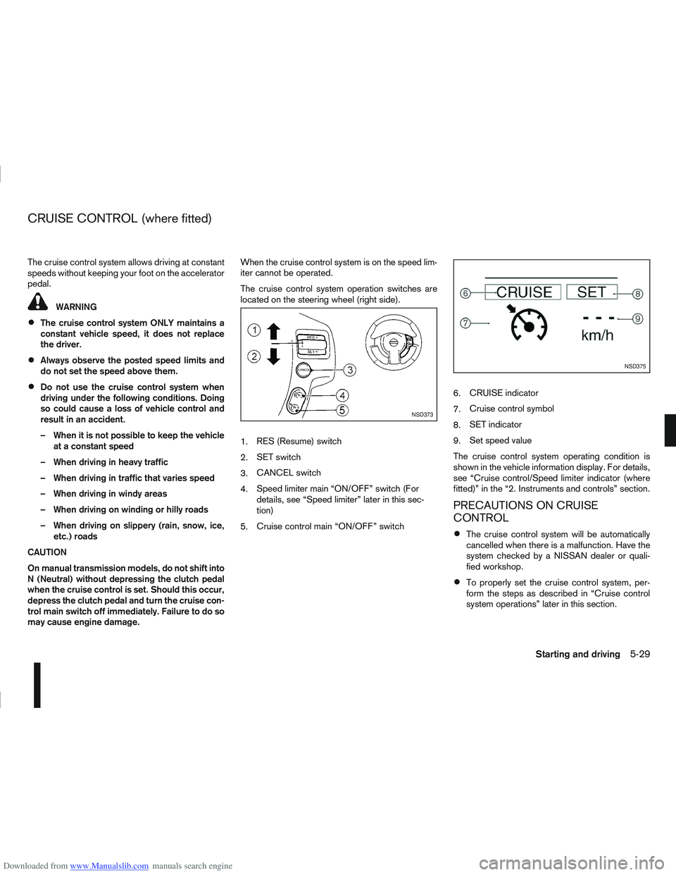
The cruise control system operation switches are
located on the steering wheel (right side).
1.
RES (Resume) switch
2. SET switch
3. CANCEL switch
4. Speed limiter main “ON/OFF” switch (For
details, see “Speed limiter” later in this sec-
tion)
5. Cruise control main “ON/OFF” switch 6.
CRUISE indicator
7. Cruise control symbol
8. SET indicator
9. Set speed value
The cruise control system operating condition is
shown in the vehicle information display. For details,
see “Cruise control/Speed limiter indicator (where
fitted)” in the “2. Instruments and controls” section.
PRECAUTIONS ON CRUISE
CONTROL
The cruise control system will be automatically
cancelled when there is a malfunction. Have the
system checked by a NISSAN dealer or quali-
fied workshop.
To properly set the cruise control system, per-
form the steps as described in “Cruise control
system operations” later in this section.
NSD373
NSD375
CRUISE CONTROL (where fitted)
Starting and driving5-29
Page 195 of 297
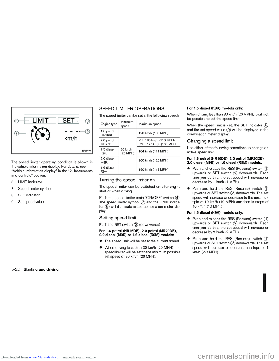
Downloaded from www.Manualslib.com manuals search engine The speed limiter operating condition is shown in
the vehicle information display. For details, see
“Vehicle information display” in the “2. Instruments
and controls” section.
6.LIMIT indicator
7. Speed limiter symbol
8. SET indicator
9. Set speed value
SPEED LIMITER OPERATIONS
The speed limiter can be set at the following speeds:
Engine type Minimum
speedMaximum speed
1.6 petrol
HR16DE
30 km/h
(20 MPH)170 km/h (105 MPH)
2.0 petrol
MR20DE MT: 190 km/h (118 MPH)
CVT: 170 km/h (105 MPH)
1.5 diesel
K9K 184 km/h (114 MPH)
2.0 diesel
M9R 200 km/h (125 MPH)
1.6 diesel
R9M 190 km/h (118 MPH)
Turning the speed limiter on
The speed limiter can be switched on after engine
start or when driving.
Push the speed limiter main “ON/OFF” switch
j4.
The speed limiter symbolj7 and the LIMIT indica-
torj6 will illuminate in the combination meter dis-
play.
Setting speed limit
Push the SET switchj2 (downwards)
For 1.6 petrol (HR16DE), 2.0 petrol (MR20DE),
2.0 diesel (M9R) or 1.6 diesel (R9M) models:
The speed limit will be set at the current speed.
When driving less than 30 km/h (20 MPH), the
speed limiter will be set to the minimum possible
set speed of 30 km/h (20 MPH). For 1.5 diesel (K9K) models only:
When driving less than 30 km/h (20 MPH), it will not
be possible to set the speed limit.
When the speed limit is set, the SET indicator
j8
and the set speed valuej9 will be displayed in the
combination meter display.
Changing a speed limit
Use either of the following operations to change an
active speed limit:
For 1.6 petrol (HR16DE), 2.0 petrol (MR20DE),
2.0 diesel (M9R) or 1.6 diesel (R9M) models:
Push and release the RES (Resume) switchj1
upwards or SET switchj2 downwards. Each
time you do this, the set speed will increase or
decrease by 1 km/h (1 MPH).
Push and hold the RES (Resume) switchj1
upwards or SET switchj2 downwards. The set
speed will increase or decrease to the next mul-
tiple of 10 km/h (10 MPH) and then in steps of
10 km/h (10 MPH).
For 1.5 diesel (K9K) models only:
Push and release the RES (Resume) switchj1
upwards or SET switchj2 downwards. Each
time you do this, the set speed will increase or
decrease by 2 km/h (2 MPH).
Push and hold the RES (Resume) switchj1
upwards or SET switchj2 downwards. The set
speed will increase or decrease in steps of 4
km/h (2-3 MPH).
NSD372
5-32Starting and driving
Page 201 of 297
Downloaded from www.Manualslib.com manuals search engine When leaving your vehicle unoccupied:
Always remove the ignition key or Intelligent Key
(where fitted) and take it with you – even in your
own garage.
Close all windows completely and lock all doors.
Always park your vehicle where it can be seen.
At night, park in a well lit area.
If the vehicle is equipped with an alarm or immo-
bilization device, use it – even for short periods.
Do not leave children and pets in the vehicle
unattended.
Do not leave valuables on view to tempt a thief.
Always take your valuables with you. If you must
leave something in your vehicle, lock it in the lug-
gage compartment or hide it out of sight.
Do not leave the vehicle documents in your ve-
hicle. In the unfortunate event of your vehicle
being stolen, the documents will only help a thief
to sell the vehicle.
Do not leave articles on a roof rack as they are
particularly vulnerable. If possible, remove them
from the rack and lock them inside the vehicle.
Do not leave the spare key or Intelligent Key in
the vehicle – keep it in a safe place at home.
Do not leave a note of your vehicle’s key number
in the vehicle. A thief may break into the vehicle,
note the key number and return with a new key
and drive the vehicle.
WARNING
If the Electrically Power Assisted Steering
warning light (EPAS) illuminates while driv-
ing, the power assist for steering will be dis-
abled. Greater steering efforts are required to
operate the steering wheel, especially in
sharp turns and at low speed. Stop the ve-
hicle as soon as safely possible and contact a
NISSAN dealer or qualified workshop for fur-
ther assistance.
In certain circumstances, factors external to
the EPAS system may contribute to the illumi-
nation of the warning light. If the warning light
illuminates, stop the vehicle as soon as safely
possible if driving. Turn the ignition switch to
the “OFF” position and wait for approximately
20 seconds, then turn the ignition switch to
the ON position again. If the light remains illu-
minated, we recommend you to contact a
NISSAN dealer or qualified workshop. See
“Warning/indicator lights and audible
reminders” in the “2. Instruments and
controls” section for further details regarding
the EPAS warning light.
The EPAS (Electrically Power Assisted Steering)
system is designed to assist steering.
The steering may appear to feel slightly stiff follow-
ing parking manoeuvres including a great deal of
steering. This is not a malfunction; it is caused by a
control system designed to prevent the motor from overheating. No servicing is required. The EPAS
system will return to normal operation the next time
the vehicle is driven.
Similarly, the EPAS system may not provide full as-
sistance during periods of reduced battery voltage
but will recover once normal battery voltage is re-
stored.
If the EPAS warning light comes on while the engine
is running, it may indicate that the EPAS system is
not working properly. As result greater steering ef-
forts are required to steer the steering wheel, espe-
cially in sharp turns and at low speeds. Have the
system checked by a NISSAN dealer or qualified
workshop as soon as possible.
NOTE
Incorrectly inflated tyres can lead to poor steer-
ing ability and make the driver suspect a steering
problem: keep the vehicle’s tyres inflated to the
correct pressure at all times.
CAUTION
Any malfunction or accident that could have dam-
aged the steering components (including actual
or attempted theft damage) should be reported
to a NISSAN dealer or qualified workshop.
VEHICLE SECURITY
POWER STEERING SYSTEM
5-38Starting and driving
Page 203 of 297

Downloaded from www.Manualslib.com manuals search engine and varies the brake fluid pressure to prevent each
wheel from locking and sliding. By preventing each
wheel from locking, the system helps the driver to
maintain steering control and helps to minimise
swerving and spinning on slippery surfaces.
Using the system
Depress the brake pedal and hold it down. Depress
the brake pedal with firm steady pressure, but do
not pump the brakes. The ABS will operate to pre-
vent the wheels from locking up. Steer the vehicle to
avoid obstacles.
WARNING
Do not pump the brake pedal. Doing so may in-
crease the stopping distance.
Self-test feature
The ABS includes electronic sensors, electric
pumps, hydraulic solenoids and a computer. The
computer has a built-in diagnostic feature that tests
the system each time you start the engine and move
thevehicleatalowspeedinforwardorreverse.
When the self-test occurs, you may hear a “clunk”
noise and/or feel a pulsation in the brake pedal. This
is normal and does not indicate a malfunction. If the
computer senses a malfunction, it switches the ABS
off and illuminates the ABS warning light on the
instrument panel. The brake system then operates
normally, but without anti-lock assistance.
If the ABS warning light illuminates during the self-
test or while driving, have the vehicle checked by a
NISSAN dealer or qualified workshop.
Normal operation
The ABS will not initiate at speeds below 5 to 10
km/h (3 to 6 MPH). The speeds will vary according
to road conditions.
When the ABS senses that one or more wheels are
close to locking up, the actuator rapidly applies and
releases hydraulic pressure. This action is similar to
pumping the brakes very quickly. You may feel a
pulsation in the brake pedal and hear a noise from
the actuator under the bonnet when it is operating.
This is normal and indicates that the ABS is working
properly. However, the pulsation may indicate that
road conditions are hazardous and extra care is re-
quired while driving. When accelerating, driving on slippery surfaces or
suddenly avoiding obstacles on roads, the vehicle
might swerve or slip. The Electronic Stability Pro-
gramme (ESP) system continuously monitors and
compares the driver’s intended speed and the travel
direction. The system adjusts wheel brake pressure
and engine torque to assist in improving vehicle sta-
bility.
When the ESP system is operating, the “SLIP”
indicator light () in the combination meter
blinks.
When only the traction control (TCS) system in
the ESP system is operating, the “SLIP” indica-
tor light (
) in the combination meter will also
blink.
If the “SLIP” indicator light () blinks, the
road conditions are slippery. Be sure to drive
carefully. See “Warning/indicator lights and au-
dible reminders” in the “2. Instruments and
controls” section.
Indicator light
If a malfunction occurs in the system, the “SLIP”
indicator light (
) and the ESP indicator light
() come on in the combination meter.
As long as these indicator lights are on, the trac-
tion control function is cancelled.
The ESP system uses Active Brake Limited Slip
(ABLS) system to improve vehicle traction. The Ac-
tive Brake Limited Slip (ABLS) system works when
one of the driving wheels is spinning on a slippery
ELECTRONIC STABILITY
PROGRAMME (ESP) SYSTEM
(where fitted)
5-40Starting and driving
Page 211 of 297
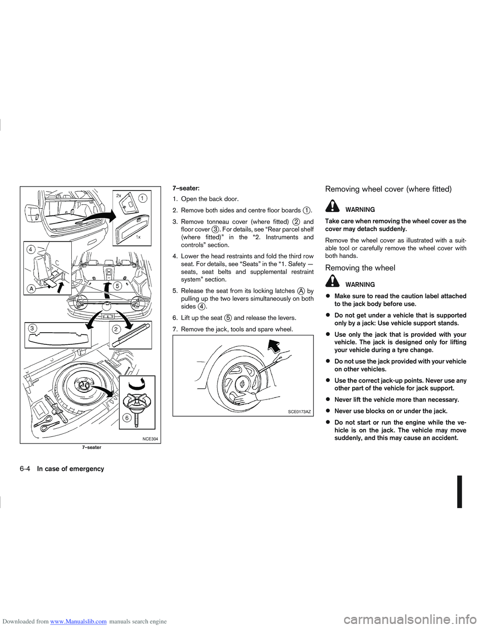
Downloaded from www.Manualslib.com manuals search engine 7–seater:
1. Open the back door.
2. Remove both sides and centre floor boards
j1.
3. Remove tonneau cover (where fitted)
j2 and
floor coverj3 . For details, see “Rear parcel shelf
(where fitted)” in the “2. Instruments and
controls” section.
4. Lower the head restraints and fold the third row seat. For details, see “Seats” in the “1. Safety —
seats, seat belts and supplemental restraint
system” section.
5. Release the seat from its locking latches
jAby
pulling up the two levers simultaneously on both
sides
j4.
6. Lift up the seat
j5 and release the levers.
7. Remove the jack, tools and spare wheel.
Removing wheel cover (where fitted)
WARNING
Take care when removing the wheel cover as the
cover may detach suddenly.
Remove the wheel cover as illustrated with a suit-
able tool or carefully remove the wheel cover with
both hands.
Removing the wheel
WARNING
Make sure to read the caution label attached
to the jack body before use.
Do not get under a vehicle that is supported
only by a jack: Use vehicle support stands.
Use only the jack that is provided with your
vehicle. The jack is designed only for lifting
your vehicle during a tyre change.
Do not use the jack provided with your vehicle
on other vehicles.
Use the correct jack-up points. Never use any
other part of the vehicle for jack support.
Never lift the vehicle more than necessary.
Never use blocks on or under the jack.
Do not start or run the engine while the ve-
hicle is on the jack. The vehicle may move
suddenly, and this may cause an accident.
NCE304
7–seater
SCE0173AZ
6-4In case of emergency
Page 216 of 297
Downloaded from www.Manualslib.com manuals search engine Repairing tyre
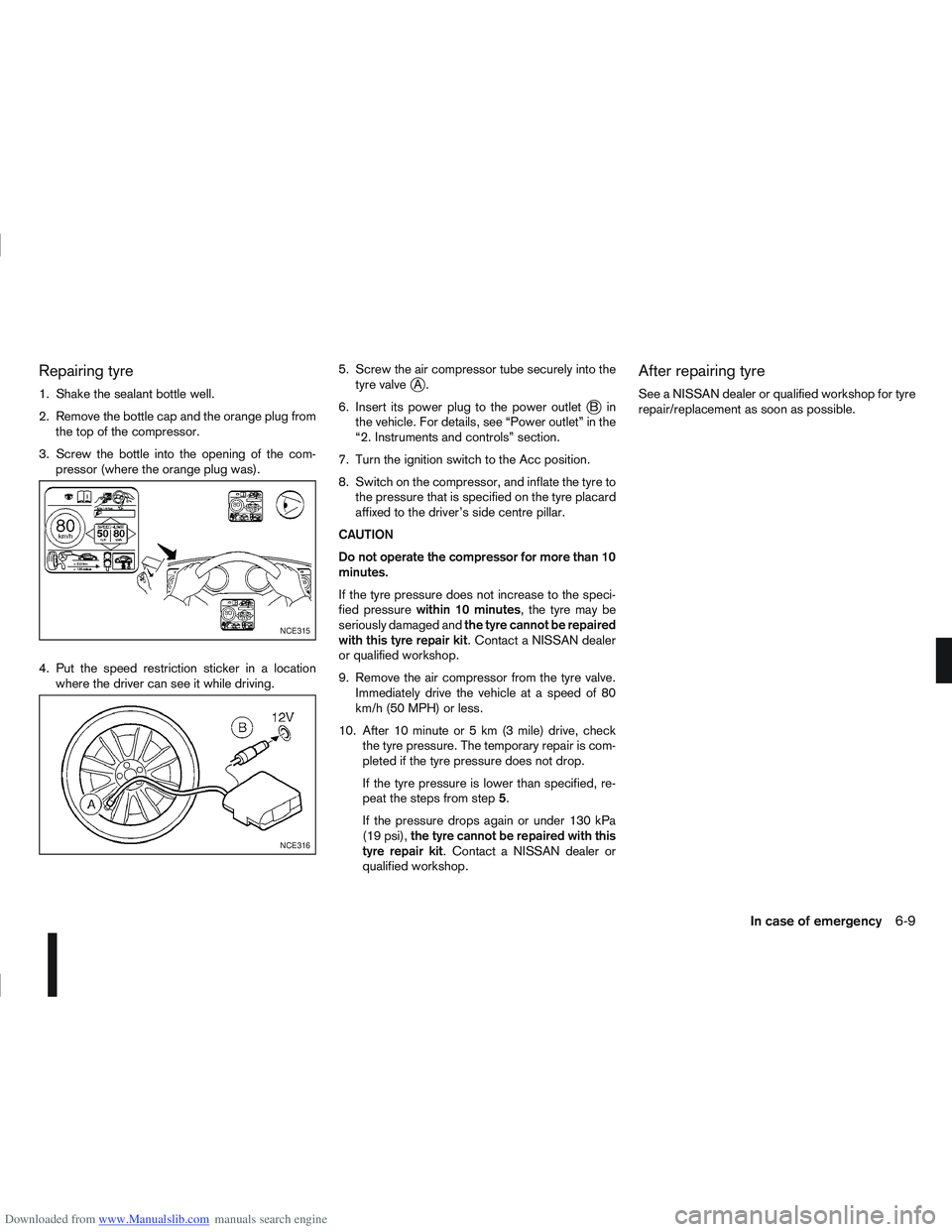
1. Shake the sealant bottle well.
2. Remove the bottle cap and the orange plug fromthe top of the compressor.
3. Screw the bottle into the opening of the com- pressor (where the orange plug was).
4. Put the speed restriction sticker in a location where the driver can see it while driving. 5. Screw the air compressor tube securely into the
tyre valvejA.
6. Insert its power plug to the power outlet
jBin
the vehicle. For details, see “Power outlet” in the
“2. Instruments and controls” section.
7. Turn the ignition switch to the Acc position.
8. Switch on the compressor, and inflate the tyre to the pressure that is specified on the tyre placard
affixed to the driver’s side centre pillar.
CAUTION
Do not operate the compressor for more than 10
minutes.
If the tyre pressure does not increase to the speci-
fied pressure within 10 minutes , the tyre may be
seriously damaged and the tyre cannot be repaired
with this tyre repair kit . Contact a NISSAN dealer
or qualified workshop.
9. Remove the air compressor from the tyre valve. Immediately drive the vehicle at a speed of 80
km/h (50 MPH) or less.
10. After 10 minute or 5 km (3 mile) drive, check the tyre pressure. The temporary repair is com-
pleted if the tyre pressure does not drop.
If the tyre pressure is lower than specified, re-
peat the steps from step 5.
If the pressure drops again or under 130 kPa
(19 psi), the tyre cannot be repaired with this
tyre repair kit. Contact a NISSAN dealer or
qualified workshop.
After repairing tyre
See a NISSAN dealer or qualified workshop for tyre
repair/replacement as soon as possible.
NCE315
NCE316
In case of emergency6-9
Page 249 of 297

Downloaded from www.Manualslib.com manuals search engine Battery (Type A)
Check the fluid level in each cell. It should be be-
tween the UPPERj1 and LOWERj2 level lines.
If it is necessary to add fluid, add only distilled water
to bring the level to the indicator in each filler open-
ing. Do not overfill.
1. Remove the cell plugs
jA using a suitable tool.
j1 OK
j2ADD
2. Add distilled water up to the UPPER level line
j1.
If the side of the battery is not clear, check the
electrolyte water level by looking directly above
the cell, as illustrated.
3. Tighten cell plugs.
CAUTION
Do not overfill battery cells. Excessive electrolyte
may leak out of the battery during charging, and
cause paint damage.
Maintenance free battery (Type B)
For a maintenance free battery it is not required to
check the fluid level. However, NISSAN recom-
mends to visually check the green indicator
jA sta-
tus periodically. If it is not visible, replace the battery
as soon as possible.
Reinitialisation procedure after battery
reconnection
If the battery has been reconnected, check the fol-
lowing items:
Re-enter the anti-theft system code (where fit-
ted). For details, see the separately provided
NISSAN Connect Owner’s Manual.
Clock setting. For details, see “Vehicle informa-
tion display” in the “2. Instruments and controls”
section or the separately provided NISSAN Con-
nect (where fitted) Owner’s Manual.
The C-View® sunshade or power window sys-
tem may need to be reinitialised. For details, see
“C-View® glass roof (where fitted)” in the “2. In-
struments and controls” section or “Windows”
in the “2. Instruments and controls” section.
Models with Stop/Start System
Ensure that the battery fitted is the special bat-
tery that is enhanced with regard to the charge-
discharge capacity and life performance. Avoid
using any other battery for the Stop/Start Sys-
tem, as this may cause early deterioration of the
battery or a malfunction of the Stop/Start Sys-
tem. It is recommended that a Genuine NISSAN
battery is fitted. For more information, contact a
NISSAN dealer or qualified workshop.
If the battery terminal is disconnected (for bat-
tery replacement, etc.) and then reconnected,
there may be some delay before the Stop/Start
System reactivates.
DI0137MAZ
NDI688Z
Indicator
NDI920Z
8-18Maintenance and do-it-yourself