2009 NISSAN MURANO ESP
[x] Cancel search: ESPPage 325 of 443
Black plate (325,1)
Model "Z51-D" EDITED: 2007/ 10/ 2
cranking by pushing the ignition switch
to OFF. After cranking the engine,
release the accelerator pedal. Crank
the enginewith your foot off the
accelerator pedalby depressing the
brake pedal and pushing the push-
button ignition switch to start the engine.
If the engine starts, but fails to run,
repeat the above procedure.
CAUTION
Do not operate the starter for more
than 15 seconds at a time. If the engine
does not start, push the ignition switch
to OFF and wait 10 seconds before
cranking again, otherwise the starter
could be damaged.
4.Warm-up
Allow the engine to idle for at least 30
seconds after starting. Do not race the
engine while warming it up. Drive at
moderate speed for a short distance first,
especially in cold weather. In cold weather,
keep the engine running for a minimum of 2 -
3 minutes before shutting it off. Starting and
stopping the engine over a short period of
time may make the vehicle more difficult to
start.5. To stop the engine, shift the selector lever to
the P (Park) position and push the ignition
switch to the OFF position.
CONTINUOUSLY VARIABLE TRANS-
MISSION (CVT)
The Continuously Variable Transmission (CVT)
in your vehicle is electronically controlled to
produce maximum power and smooth operation.
The recommended operating procedures for this
transmission are shown on the following pages.
Follow these procedures for maximum vehicle
performance and driving enjoyment.
Engine power may be automatically re-
duced to protect the CVT if the engine
speed increases quickly when driving on
slippery roads or while being tested on
some dynamometers.
Starting the vehicle
1. After starting the engine, fully depress the
foot brake pedal before moving the selector
lever out of the P (Park) position.
This CVT is designed so that the foot
brake pedal must be depressed before
shifting from P (Park) to any driving
position while the ignition switch is in
the ON position.
The selector lever cannot be moved out
of the P (Park) position and into any of
the other positions if the ignition
switch is pushed to the LOCK, OFF or
ACC position.
DRIVING THE VEHICLE
Starting and driving5-13
Page 328 of 443
Black plate (328,1)
Model "Z51-D" EDITED: 2007/ 10/ 2
Accelerator downshift
— In D position —
For passing or hill climbing, fully depress the
accelerator pedal to the floor. This shifts the
transmission down into a lower gear, depending
on the vehicle speed.
High fluid temperature protection mode
This transmission has a high fluid temperature
protection mode. If the fluid temperature be-
comes too high (for example, when climbing
steep grades in high temperature with heavy
loads, such as when towing a trailer) , engine
power and, under some conditions, vehicle
speed will be decreased automatically to reduce
the chance of transmission damage. Vehicle
speed can be controlled with the accelerator
pedal, but the engine and vehicle speed may be
limited.
Fail-safe
If the vehicle is driven under extreme
conditions, such as excessive wheel spin-
ning and subsequent hard braking, the
fail-safe system may be activated. The MIL
may illuminate to indicate the fail-safe
mode is activated. (See “Malfunction In-
dicator Light (MIL)” in the “2. Instruments
and controls” section.) This will occur even
if all electrical circuits are functioning
properly. In this case, turn the ignition
switch to the OFF position and wait for 10seconds. Then turn the switch back to the
ON position. The vehicle should return to
its normal operating condition. If it does
not return to its normal operating condi-
tion, have a NISSAN dealer check the
transmission and repair if necessary.
WARNING
When the high fluid temperature pro-
tection mode or fail-safe operation
occurs, vehicle speed may be gradually
reduced. The reduced speed may be
lower than other traffic, which could
increase the chance of a collision. Be
especially careful when driving. If ne-
cessary, pull to the side of the road at a
safe place and allow the transmission
to return to normal operation, or have it
repaired if necessary.
SSD0693
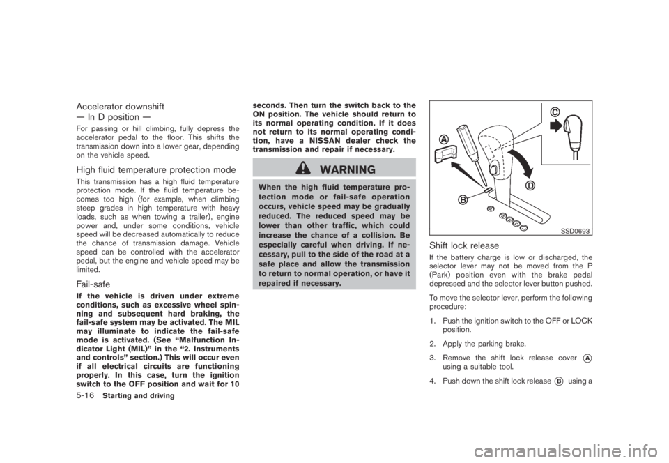
Shift lock release
If the battery charge is low or discharged, the
selector lever may not be moved from the P
(Park) position even with the brake pedal
depressed and the selector lever button pushed.
To move the selector lever, perform the following
procedure:
1. Push the ignition switch to the OFF or LOCK
position.
2. Apply the parking brake.
3. Remove the shift lock release cover
*Ausing a suitable tool.
4. Push down the shift lock release
*Busing a
5-16Starting and driving
Page 334 of 443
Black plate (334,1)
Model "Z51-D" EDITED: 2007/ 10/ 2
*2: LOCK mode will change to AUTO mode
automatically when the vehicle has been
driven at a high speed. The AWD LOCK
indicator light turns off.
*3: LOCK mode will automatically be cancelled
when the ignition switch is turned to the OFF
position.
.If the AWD LOCK switch is operated while
accelerating or decelerating, or if the ignition
switch is turned off, you may feel a jolt. This
is normal.
.The oil temperature of power train parts will
increase if the vehicle is continuously
operated under conditions where the differ-
ence in rotation between the front and rear
wheels is large (wheel slip) , such as when
driving the vehicle on rough roads through
sand, mud or freeing a stuck vehicle. In
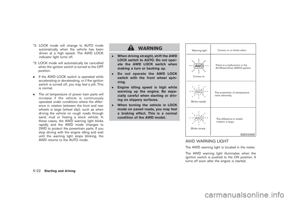
these cases, the AWD warning light blinks
rapidly and the AWD mode changes to
2WD to protect the powertrain parts. If you
stop driving with the engine idling and wait
until the warning light stops blinking, the
AWD returns to the AUTO mode.WARNING
.When driving straight, shift the AWD
LOCK switch to AUTO. Do not oper-
ate the AWD LOCK switch when
making a turn or backing up.
.Do not operate the AWD LOCK
switch with the front wheel spin-
ning.
.Engine idling speed is high while
warming up the engine. Be espe-
cially careful when starting or driv-
ing on slippery surfaces.
.When turning the vehicle in LOCK
mode on paved roads, you may feel
a braking effect. This is a normal
condition of the AWD model.
SSD0336B
AWD WARNING LIGHT
The AWD warning light is located in the meter.
The AWD warning light illuminates when the
ignition switch is pushed to the ON position. It
turns off soon after the engine is started.
5-22Starting and driving
Page 337 of 443
Black plate (337,1)
Model "Z51-D" EDITED: 2007/ 10/ 2
WARNING
If the engine is not running or is turned
off while driving, the power assist for
the steering will not work. Steering will
be harder to operate.
The power assisted steering uses a hydraulic
pump, driven by the engine, to assist steering.
If the engine stops or the drive belt breaks, you
will still have control of the vehicle. However,
much greater steering effort is needed, espe-
cially in sharp turns and at low speeds.
BRAKING PRECAUTIONS
The brake system has two separate hydraulic
circuits. If one circuit malfunctions, you will still
have braking at two wheels.
Vacuum assisted brakes
The brake booster aids braking by using engine
vacuum. If the engine stops, you can stop the
vehicle by depressing the brake pedal. However,
greater foot pressure on the brake pedal will be
required to stop the vehicle and the stopping
distance will be longer.
Using the brakes
Avoid resting your foot on the brake pedal while
driving. This will cause overheating of the
brakes, wearing out the brake and pads faster
and reduce gas mileage.
To help reduce brake wear and to prevent the
brakes from overheating, reduce speed and
downshift to a lower gear before going down a
slope or long grade. Overheated brakes may
reduce braking performance and could result in
loss of vehicle control.
WARNING
.While driving on a slippery surface,
be careful when braking, accelerat-
ing or downshifting. Abrupt brakingor accelerating could cause the
wheelstoskidandresultinan
accident.
.If the engine is not running or is
turned off while driving, the power
assist for the brakes will not work.
Braking will be harder.
Wet brakes
When the vehicle is washed or driven through
water, the brakes may get wet. As a result, your
braking distance will be longer and the vehicle
may pull to one side during braking.
To dry brakes, drive the vehicle at a safe speed
while lightly tapping the brake pedal to heat-up
the brakes. Do this until the brakes return to
normal. Avoid driving the vehicle at high speeds
until the brakes function correctly.
PARKING BRAKE BREAK-IN
Break in the parking brake shoes whenever the
stopping effect of the parking brake is weakened
or whenever the parking brake shoes and/or
drums/rotors are replaced, in order to assure the
best braking performance.
This procedure is described in the vehicle
service manual and can be performed by a
NISSAN dealer.
POWER STEERING BRAKE SYSTEM
Starting and driving5-25
Page 338 of 443
Black plate (338,1)
Model "Z51-D" EDITED: 2007/ 10/ 2
ANTI-LOCK BRAKING SYSTEM (ABS)
WARNING
.The Anti-lock Braking System (ABS)
is a sophisticated device, but it
cannot prevent accidents resulting
from careless or dangerous driving
techniques. It can help maintain
vehicle control during braking on
slippery surfaces. Remember that
stopping distances on slippery sur-
faces will be longer than on normal
surfaces even with ABS. Stopping
distances may also be longer on
rough, gravel or snow covered
roads, or if you are using tire chains.
Alwaysmaintainasafedistance
from the vehicle in front of you.
Ultimately, the driver is responsible
for safety.
.Tire type and condition may also
affect braking effectiveness.
— When replacing tires, install the
specified size of tires on all four
wheels.
— When installing a spare tire,
make sure that it is the proper
size and type as specified on theTire and Loading Information
label. See “TIRE AND LOADING
INFORMATION LABEL” in the “9.
Technical and consumer infor-
mation” section of this manual.
— For detailed information, see
“WHEELS AND TIRES” in the
“8. Maintenance and do-it-your-
self” section of this manual.
The Anti-lock Braking System (ABS) controls
the brakes so the wheels do not lock during hard
braking or when braking on slippery surfaces.
The system detects the rotation speed at each
wheel and varies the brake fluid pressure to
prevent each wheel from locking and sliding. By
preventing each wheel from locking, the system
helps the driver maintain steering control and
helps to minimize swerving and spinning on
slippery surfaces.
Using the system
Depress the brake pedal and hold it down.
Depress the brake pedal with firm steady
pressure, but do not pump the brakes. The
ABS will operate to prevent the wheels from
locking up. Steer the vehicle to avoid obstacles.
WARNING
Do not pump the brake pedal. Doing somay result in increased stopping dis-
tances.
Self-test feature
The ABS includes electronic sensors, electric
pumps, hydraulic solenoids and a computer. The
computer has a built-in diagnostic feature that
tests the system each time you start the engine
and move the vehicle at a low speed in forward
or reverse. When the self-test occurs, you may
hear a “clunk” noise and/or feel a pulsation in the
brake pedal. This is normal and does not
indicate a malfunction. If the computer senses
a malfunction, it switches the ABS off and
illuminates the ABS warning light on the
instrument panel. The brake system then oper-
ates normally, but without anti-lock assistance.
If the ABS warning light illuminates during the
self-test or while driving, have the vehicle
checked by a NISSAN dealer.
Normal operation
The ABS operates at speeds above 3 to 6 MPH
(5 to 10 km/h) . The speed varies according to
road conditions.
When the ABS senses that one or more wheels
are close to locking up, the actuator rapidly
applies and releases hydraulic pressure. This
action is similar to pumping the brakes very
quickly. You may feel a pulsation in the brake
pedal and hear a noise from under the hood or
5-26Starting and driving
Page 340 of 443

Black plate (340,1)
Model "Z51-D" EDITED: 2007/ 10/ 2
speed and be especially careful
when driving and cornering on slip-
pery surfaces and always drive care-
fully.
.Do not modify the vehicle’s suspen-
sion. If suspension parts such as
shock absorbers, struts, springs,
stabilizer bars and bushings and
wheels are not NISSAN approved
or are extremely deteriorated the
VDC system may not operate prop-
erly. This could adversely affect
vehicle handling performance, and
the “VDC OFF” indicator or “SLIP”
indicator or both indicator lights
may illuminate.
.If brake related parts such as brake
pads, rotors and calipers are not
standard equipment or are extre-
mely deteriorated, the “VDC OFF”
indicator or “SLIP” indicator or both
indicator lights may illuminate.
.If engine related parts such as
muffler are not standard equipment
or are extremely deteriorated, the
“VDC OFF” indicator or “SLIP” in-
dicator or both indicator lights may
illuminate..When driving on extremely inclined
surfaces such as higher banked
corners, the VDC system may not
operate properly and the “VDC OFF”
indicator or “SLIP” indicator or both
indicator lights may illuminate. Do
not drive on these types of roads.
.When driving on unstable surfaces
such as a turntable, ferry, elevator
or ramp, the “VDC OFF” indicator or
“SLIP” indicator or both indicator
lights may illuminate. This is not a
malfunction. Restart the engine
after driving onto a stable surface.
.If wheels or tires other than those
recommended are used, the VDC
system may not operate properly
and “VDC OFF” indicator or “SLIP”
indicator or both indicator lights
may illuminate.
.The VDC system is not a substitute
for winter tires or tire chains on a
snow covered road.FREEING A FROZEN DOOR LOCK
To prevent a door lock from freezing, apply
deicer through the key hole. If the lock becomes
frozen, heat the key before inserting it into the
key hole or use the remote keyless entry keyfob.
ANTI-FREEZE
In the winter when it is anticipated that the
outside temperature will drop below 328F(08C) ,
check the anti-freeze to assure proper winter
protection. For additional information, see “EN-
GINE COOLING SYSTEM” in the “8. Main-
tenance and do-it-yourself” section.
BATTERY
If the battery is not fully charged during
extremely cold weather conditions, the battery
fluid may freeze and damage the battery. To
maintain maximum efficiency, the battery should
be checked regularly. For additional information,
see “BATTERY” in the “8. Maintenance and do-
it-yourself” section.
DRAINING OF COOLANT WATER
If the vehicle is to be left outside without anti-
freeze, drain the cooling system, including the
engine block. Refill before operating the vehicle.
For details, see “ENGINE COOLING SYSTEM”
in the “8. Maintenance and do-it-yourself”
section.
COLD WEATHER DRIVING
5-28Starting and driving
Page 347 of 443
Black plate (349,1)
Model "Z51-D" EDITED: 2007/ 10/ 2
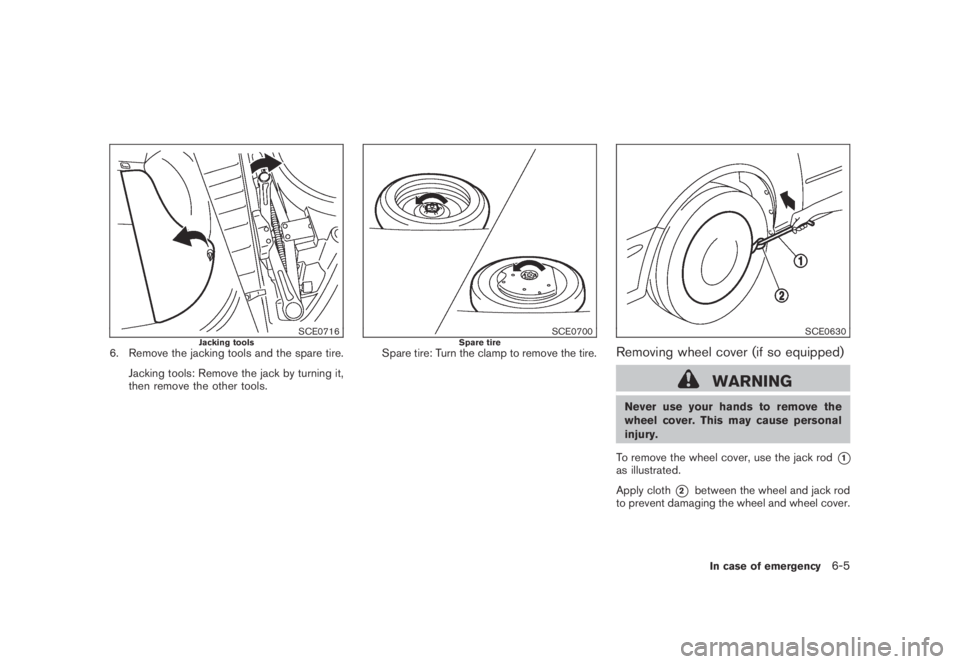
SCE0716Jacking tools6. Remove the jacking tools and the spare tire.
Jacking tools: Remove the jack by turning it,
then remove the other tools.
SCE0700Spare tireSpare tire: Turn the clamp to remove the tire.
SCE0630
Removing wheel cover (if so equipped)
WARNING
Never use your hands to remove the
wheel cover. This may cause personal
injury.
To remove the wheel cover, use the jack rod
*1as illustrated.
Apply cloth
*2between the wheel and jack rod
to prevent damaging the wheel and wheel cover.
In case of emergency6-5
Page 350 of 443
Black plate (352,1)
Model "Z51-D" EDITED: 2007/ 10/ 2
than 2 times, until they are tight.
4. Lower the vehicle slowly until the tire
touches the ground. Then, with the wheel
nut wrench, tighten the wheel nuts securely
in the sequence as illustrated. Lower the
vehicle completely.
WARNING
.Incorrect wheel nuts or improperly
tightened wheel nuts can cause the
wheel to become loose or come off.
This could cause an accident.
.Do not use oil or grease on the
wheel studs or nuts. This could
cause the nuts to become loose.
.Retighten the wheel nuts when the
vehicle has been driven for 600
miles (1,000 km) (also in cases of a
flat tire, etc.) .
.As soon as possible, tighten the
wheel nuts to the specified torque
with a torque wrench.
Wheel nut tightening torque:
80 ft-lb (108 N·m)
The wheel nuts must be kept tightened
to specification at all times. It is
recommended that wheel nuts be tigh-tened to specifications at each lubrica-
tion interval.
.Adjust tire pressure to the COLD
pressure.
COLD pressure:
After the vehicle has been parked for
three hours or more or driven less than
1 mile (1.6 km) .
COLD tire pressures are shown on the
Tire and Loading Information label
affixed to the driver side center pillar.
Stowing the damaged tire and the tools
1. Securely store the damaged tire, jack and
tools in the storage area.
2. Replace the cargo box.
3. Close the cargo floor board.
4. Close the lift gate.
WARNING
.Always make sure that the spare tire
and jacking equipment are properly
secured after use. Such items can
become dangerous projectiles in an
accident or sudden stop.
.The T-type spare tire and small sizespare tire are designed for emer-
gency use. See specific instructions
under the heading “WHEELS AND
TIRES” in the “8. Maintenance and
do-it-yourself” section.
6-8In case of emergency