2009 NISSAN MURANO wheel
[x] Cancel search: wheelPage 88 of 443
Black plate (86,1)
Model "Z51-D" EDITED: 2007/ 10/ 2
SIC3577
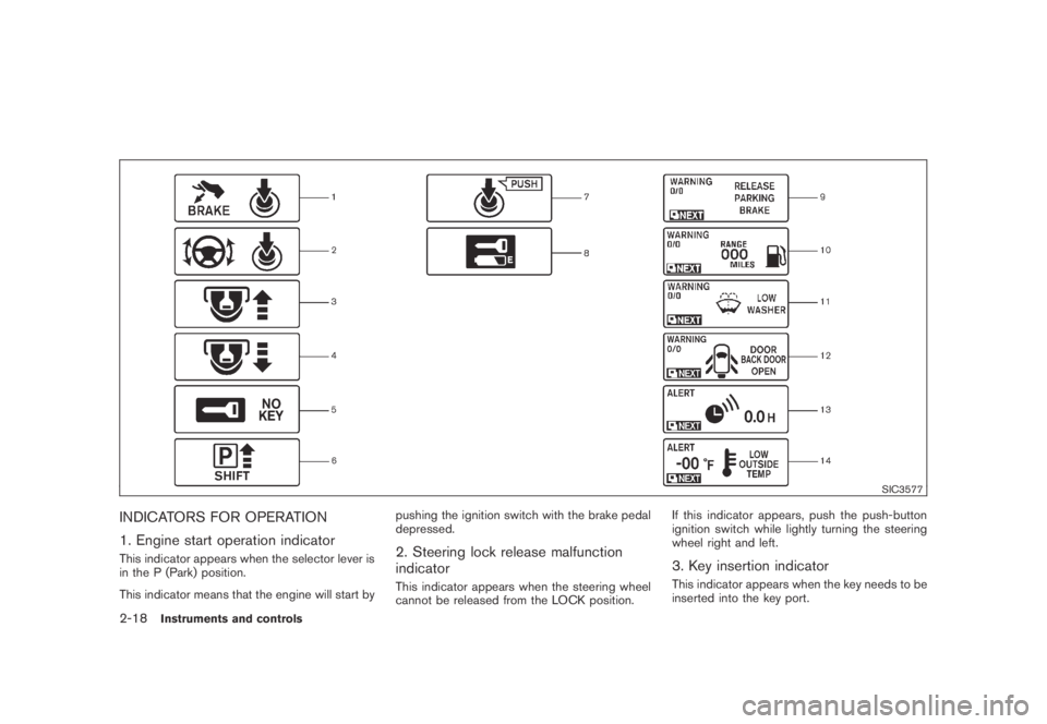
INDICATORS FOR OPERATION
1. Engine start operation indicator
This indicator appears when the selector lever is
in the P (Park) position.
This indicator means that the engine will start bypushing the ignition switch with the brake pedal
depressed.2. Steering lock release malfunction
indicator
This indicator appears when the steering wheel
cannot be released from the LOCK position.If this indicator appears, push the push-button
ignition switch while lightly turning the steering
wheel right and left.
3. Key insertion indicator
This indicator appears when the key needs to be
inserted into the key port.
2-18Instruments and controls
Page 107 of 443
Black plate (105,1)
Model "Z51-D" EDITED: 2007/ 10/ 2
.Turn signals do not work when the
hazard warning flasher lights are
on.
The flasher can be actuated with the ignition
switch in any position.
Some state laws may prohibit the use of
the hazard warning flasher switch while
driving.
SIC3586
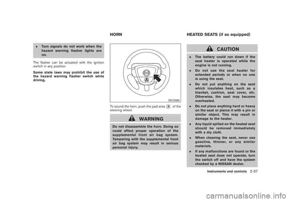
To sound the horn, push the pad area*Aof the
steering wheel.
WARNING
Do not disassemble the horn. Doing so
could affect proper operation of the
supplemental front air bag system.
Tampering with the supplemental front
air bag system may result in serious
personal injury.
CAUTION
.The battery could run down if the
seat heater is operated while the
engine is not running.
.Do not use the seat heater for
extended periods or when no one
is using the seat.
.Do not put anything on the seat
which insulates heat, such as a
blanket, cushion, seat cover, etc.
Otherwise, the seat may become
overheated.
.Do not place anything hard or heavy
on the seat or pierce it with a pin or
similar object. This may result in
damage to the heater.
.Any liquid spilled on the heated seat
should be removed immediately
with a dry cloth.
.When cleaning the seat, never use
gasoline, thinner, or any similar
materials.
.If any malfunctions are found or the
heated seat does not operate, turn
the switch off and have the system
checked by a NISSAN dealer.
HORN HEATED SEATS (if so equipped)
Instruments and controls2-37
Page 109 of 443

Black plate (107,1)
Model "Z51-D" EDITED: 2007/ 10/ 2
5. Push the CLOCK button*1or AUDIO
knob
*2to enter.
The display will return to the regular clock
display after 10 seconds.
If the power supply is disconnected, the clock
will not indicate the correct time.
Readjust the time.
MODELS WITH COLOR DISPLAY
For adjusting the time, see “Clock settings” in
the “4. Monitor, heater, air conditioner, audio,
phone and voice recognition systems” section.
SIC1881
The vehicle should be driven with the Vehicle
Dynamic Control (VDC) system on for most
driving conditions.
If the vehicle is stuck in mud or snow, the VDC
system reduces the engine output to reduce
wheel spin. The engine speed will be reduced
even if the accelerator is depressed to the floor.
If maximum engine power is needed to free a
stuck vehicle, turn the VDC system off.
To turn off the VDC system, push the VDC OFF
switch. The
indicator will illuminate.
Push the VDC OFF switch again or restart the
engine to turn on the system. (See “VEHICLE
DYNAMIC CONTROL (VDC) SYSTEM” in the
“5. Starting and driving” section.)
SIC3587Center console
SIC3651Cargo area
VEHICLE DYNAMIC CONTROL (VDC)
OFF SWITCHPOWER OUTLET
Instruments and controls2-39
Page 138 of 443
Black plate (138,1)
Model "Z51-D" EDITED: 2007/ 10/ 2
charged, replace it with a new one.
Since the Intelligent Key is continuously receiv-
ing radio waves, if the key is left near equipment
which transmits strong radio waves, such as
signals from a TV and personal computer, the
battery life may become shorter.
For information regarding replacement of a
battery, see “BATTERY REPLACEMENT” in
the “8. Maintenance and do-it-yourself” section.
Because the steering wheel is locked electri-
cally, unlocking the steering wheel with the
ignition switch in the LOCK position is impos-
sible when the vehicle battery is completely
discharged. Pay special attention that the
vehicle battery is not completely discharged.
As many as 4 Intelligent Keys can be registered
and used with one vehicle. For information about
the purchase and use of additional Intelligent
Keys, contact a NISSAN dealer.
CAUTION
.Do not allow the Intelligent Key,
which contains electrical compo-
nents, to come into contact with
water or salt water. This could affect
the system function.
.Do not drop the Intelligent Key..Do not strike the Intelligent Key
sharply against another object.
.Do not change or modify the Intel-
ligent Key.
.Wetting may damage the Intelligent
Key. If the Intelligent Key gets wet,
immediately wipe until it is comple-
tely dry.
.Do not place the Intelligent Key for
an extended period in an area where
temperatures exceed 1408F (608C) .
.Do not attach the Intelligent Key
with a key holder that contains a
magnet.
.Do not place the Intelligent Key near
equipment that produces a mag-
netic field, such as a TV, audio
equipment and personal computers.
If an Intelligent Key is lost or stolen, NISSAN
recommends erasing the ID code of that
Intelligent Key from the vehicle. This may prevent
the unauthorized use of the Intelligent Key to
operate the vehicle. For information regarding
the erasing procedure, contact a NISSAN deal-
er.
SPA1948A
INTELLIGENT KEY OPERATING
RANGE
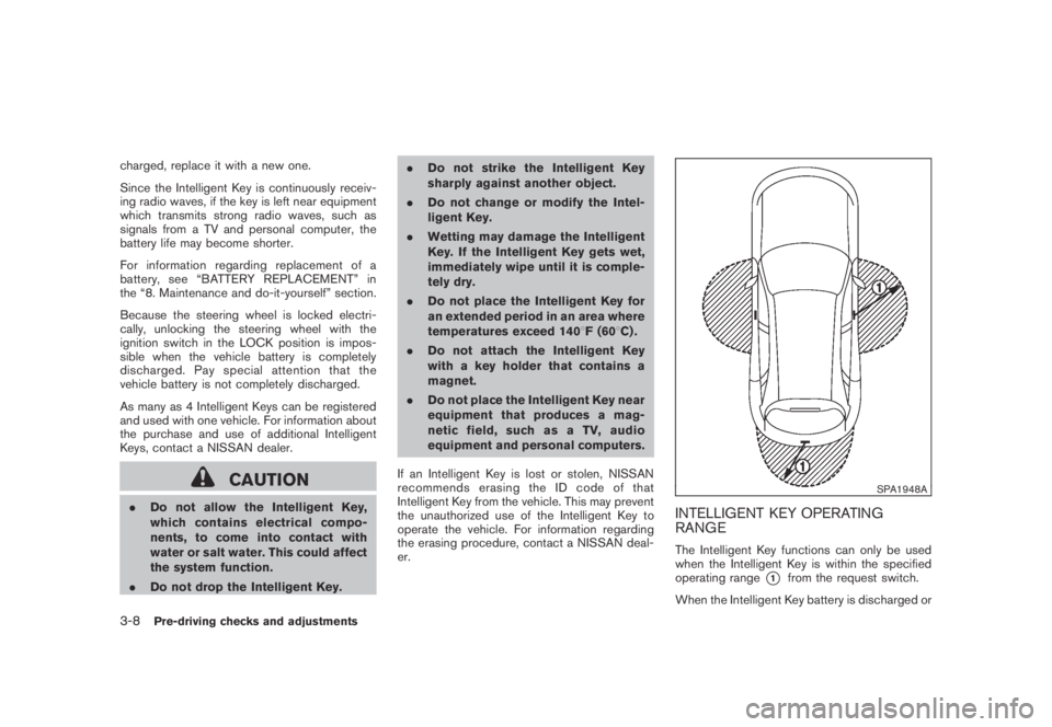
The Intelligent Key functions can only be used
when the Intelligent Key is within the specified
operating range
*1from the request switch.
When the Intelligent Key battery is discharged or
3-8Pre-driving checks and adjustments
Page 155 of 443
Black plate (155,1)
Model "Z51-D" EDITED: 2007/ 10/ 2
WARNING
.Do not adjust the steering wheel
while driving. You could lose control
of your vehicle and cause an acci-
dent.
.Do not adjust the steering wheel
any closer to you than is necessary
for proper steering operation and
comfort. The driver’s air bag inflates
with great force. If you are unrest-
rained, leaning forward, sitting side-
ways or out of position in any way,
you are at greater risk of injury or
death in a crash. You may also
receive serious or fatal injuries from
the air bag if you are up against it
when it inflates. Always sit back
against the seatback and as far
away as practical from the steering
wheel. Always use the seat belts.
SPA2443
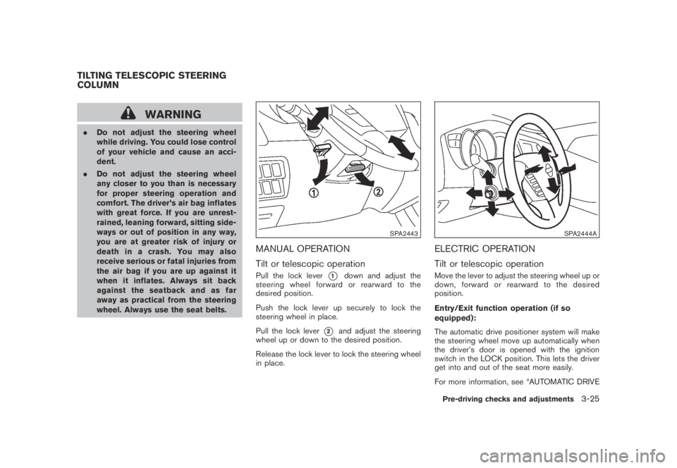
MANUAL OPERATION
Tilt or telescopic operation
Pull the lock lever*1down and adjust the
steering wheel forward or rearward to the
desired position.
Push the lock lever up securely to lock the
steering wheel in place.
Pull the lock lever
*2and adjust the steering
wheel up or down to the desired position.
Release the lock lever to lock the steering wheel
in place.
SPA2444A
ELECTRIC OPERATION
Tilt or telescopic operation
Move the lever to adjust the steering wheel up or
down, forward or rearward to the desired
position.
Entry/Exit function operation (if so
equipped):
The automatic drive positioner system will make
the steering wheel move up automatically when
the driver’s door is opened with the ignition
switch in the LOCK position. This lets the driver
get into and out of the seat more easily.
For more information, see “AUTOMATIC DRIVE
TILTING TELESCOPIC STEERING
COLUMN
Pre-driving checks and adjustments3-25
Page 160 of 443
Black plate (160,1)
Model "Z51-D" EDITED: 2007/ 10/ 2
The automatic drive positioner system has two
features:
.Entry/exit function
.Memory storage
ENTRY/EXIT FUNCTION
This system is designed so that the driver’s seat
and steering column will automatically move
when the selector lever is in the P (Park)
position. This allows the driver to get into and
out of the driver’s seat more easily.
The driver’s seat will slide backward and the
steering wheel will move up when the driver’s
door is opened with the ignition switch in the
LOCK position and the key not inserted in the
key port.
The driver’s seat and steering wheel will return
to the previous positions when the ignition
switch is pushed to the ACC position.
The driver’s seat will not return to the previous
positions if the seat or steering adjusting switch
is operated when the seat is at the exit position.
Cancel or activate entry/exit function
The selector lever must be in the P (Park)
position with the ignition switch in the OFF
position after the driver’s door is opened.
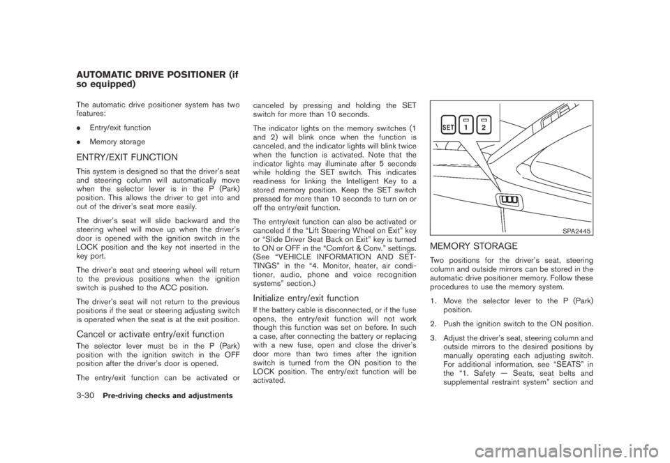
The entry/exit function can be activated orcanceled by pressing and holding the SET
switch for more than 10 seconds.
The indicator lights on the memory switches (1
and 2) will blink once when the function is
canceled, and the indicator lights will blink twice
when the function is activated. Note that the
indicator lights may illuminate after 5 seconds
while holding the SET switch. This indicates
readiness for linking the Intelligent Key to a
stored memory position. Keep the SET switch
pressed for more than 10 seconds to turn on or
off the entry/exit function.
The entry/exit function can also be activated or
canceled if the “Lift Steering Wheel on Exit” key
or “Slide Driver Seat Back on Exit” key is turned
to ON or OFF in the “Comfort & Conv.” settings.
(See “VEHICLE INFORMATION AND SET-
TINGS” in the “4. Monitor, heater, air condi-
tioner, audio, phone and voice recognition
systems” section.)
Initialize entry/exit function
If the battery cable is disconnected, or if the fuse
opens, the entry/exit function will not work
though this function was set on before. In such
a case, after connecting the battery or replacing
with a new fuse, open and close the driver’s
door more than two times after the ignition
switch is turned from the ON position to the
LOCK position. The entry/exit function will be
activated.
SPA2445
MEMORY STORAGE
Two positions for the driver’s seat, steering
column and outside mirrors can be stored in the
automatic drive positioner memory. Follow these
procedures to use the memory system.
1. Move the selector lever to the P (Park)
position.
2. Push the ignition switch to the ON position.
3. Adjust the driver’s seat, steering column and
outside mirrors to the desired positions by
manually operating each adjusting switch.
For additional information, see “SEATS” in
the “1. Safety — Seats, seat belts and
supplemental restraint system” section and
AUTOMATIC DRIVE POSITIONER (if
so equipped)
3-30Pre-driving checks and adjustments
Page 161 of 443
Black plate (161,1)
Model "Z51-D" EDITED: 2007/ 10/ 2
“TILTING TELESCOPIC STEERING COL-
UMN” earlier in this section and “OUTSIDE
MIRRORS” earlier in this section.
4. Push the SET switch and, within 5 seconds,
push the memory switch (1 or 2) .
The indicator light for the pushed memory
switch will stay on for approximately 5
seconds after pushing the switch.
If memory is stored in the same memory
switch, the previous memory will be deleted.
Linking key to a stored memory position
The key can be linked to a stored memory
position with the following procedure.
1. Follow one of the steps for storing a memory
position.
.While the indicator light for the memory
switch being set is illuminated for 5 sec-
onds, push the
button on the key.
.Push the ignition switch to the OFF position,
and then push the SET switch. Push the
button while pushing the memory
button while the indicator light stays on for
approximately 5 seconds.
If the indicator light blinks, the key is linked to
that memory setting.
Push the ignition switch to the OFF position, andthen push the
button on the key. The
driver’s seat, steering wheel and outside mirrors
will move to the memorized position.
Confirming memory storage
.Push the ignition switch to the ON position
and push the SET switch. If the main
memory has not been stored, the indicator
light will come on for approximately 0.5
second. When the memory has stored in
position, the indicator light will stay on for
approximately 5 seconds.
.If the battery cable is disconnected, or if the
fuse opens, the memory will be canceled. In
this case, reset the desired position using
the previous procedure.
.If optional keys are added to your vehicle,
the memory storage procedure to switch 1
or 2 and linking key procedure to a stored
memory position should be performed again
for each key. For additional Intelligent Key
information, see “KEYS” earlier in this
section.
Selecting the memorized position
1. Move the selector lever to the P (Park)
position.
2. Use one of the following methods to move
the driver’s seat, the outside mirrors and the
steering wheel..Push the ignition switch to the ON
position and push the memory switch
(1 or 2) .
.Within 45 seconds of opening the
driver’s door, push the memory switch
(1 or 2) .
The driver’s seat, steering column and
outside mirrors will move to the memorized
position with the indicator light flashing, and
then the light will stay on for approximately 5
seconds.
SYSTEM OPERATION
The automatic drive positioner system will not
work or will stop operating under the following
conditions:
.When the vehicle speed is above 4 MPH (7
km/h) (entry/exit function) .
.When the vehicle is driven (memory sto-
rage) .
.When the adjusting switch for the driver’s
seat and steering column is turned on while
the automatic drive positioner is operating.
.When the seat, steering column and outside
mirrors have already been moved to the
memorized position.
.When no position is stored in the memory
switch.
Pre-driving checks and adjustments3-31
Page 163 of 443
Black plate (13,1)
4 Monitor, heater, air conditioner, audio,
phone and voice recognition systems
Model "Z51-D" EDITED: 2007/ 10/ 2
Safety note....................................................... 4-2
Center multi-function control panel
(models with color display screen)......................... 4-2
How to use multi-function controller................... 4-4
How to use touch screen
(models with navigation system)........................ 4-4
Start-up screen (models with navigation system) . . . 4-6
Start menu................................................... 4-6
How to select menus on the screen................... 4-7
Vehicle information and settings............................. 4-8
How to use STATUS button.............................. 4-8
How to use brightness control and display ON/
OFF button................................................... 4-8
How to use INFO button.................................. 4-8
How to use SETTING button..........................4-12
Rearview monitor (if so equipped)........................4-19
How to read the displayed lines.......................4-20
How to park with predicted course lines............4-20
Difference between predicted and actual
distances...................................................4-22
How to adjust the screen...............................4-24
Operating tips.............................................4-24
Ventilators......................................................4-25
Heater and air conditioner..................................4-26
Automatic operation......................................4-28
Manual operation.........................................4-29
To turn the system off...................................4-30Operating tips.............................................4-30
In-cabin microfilter........................................4-30
Servicing air conditioner................................4-30
Audio system..................................................4-31
Audio operation precautions...........................4-31
FM-AM radio with Compact Disc (CD)
changer.....................................................4-39
FM-AM-SAT radio with Compact Disc (CD)
changer.....................................................4-44
CompactFlash (CF) player operation
(models with navigation system)......................4-49
iPod
®player operation (if so equipped)..............4-51
Music box hard drive
(models with navigation system)......................4-52
CD/CF (CompactFlash) care and cleaning.........4-59
Steering-wheel-mounted controls for audio
(if so equipped)...........................................4-60
Antenna.....................................................4-61
NISSAN Mobile Entertainment System (MES)
(if so equipped)...............................................4-62
DVD player operation precautions....................4-63
Digital Versatile Disc (DVD) system
components...............................................4-64
Remote controller and headphones battery
replacement................................................4-67
Before operating the DVD entertainment
system.......................................................4-68