2009 NISSAN MURANO mirror
[x] Cancel search: mirrorPage 161 of 443
Black plate (161,1)
Model "Z51-D" EDITED: 2007/ 10/ 2
“TILTING TELESCOPIC STEERING COL-
UMN” earlier in this section and “OUTSIDE
MIRRORS” earlier in this section.
4. Push the SET switch and, within 5 seconds,
push the memory switch (1 or 2) .
The indicator light for the pushed memory
switch will stay on for approximately 5
seconds after pushing the switch.
If memory is stored in the same memory
switch, the previous memory will be deleted.
Linking key to a stored memory position
The key can be linked to a stored memory
position with the following procedure.
1. Follow one of the steps for storing a memory
position.
.While the indicator light for the memory
switch being set is illuminated for 5 sec-
onds, push the
button on the key.
.Push the ignition switch to the OFF position,
and then push the SET switch. Push the
button while pushing the memory
button while the indicator light stays on for
approximately 5 seconds.
If the indicator light blinks, the key is linked to
that memory setting.
Push the ignition switch to the OFF position, andthen push the
button on the key. The
driver’s seat, steering wheel and outside mirrors
will move to the memorized position.
Confirming memory storage
.Push the ignition switch to the ON position
and push the SET switch. If the main
memory has not been stored, the indicator
light will come on for approximately 0.5
second. When the memory has stored in
position, the indicator light will stay on for
approximately 5 seconds.
.If the battery cable is disconnected, or if the
fuse opens, the memory will be canceled. In
this case, reset the desired position using
the previous procedure.
.If optional keys are added to your vehicle,
the memory storage procedure to switch 1
or 2 and linking key procedure to a stored
memory position should be performed again
for each key. For additional Intelligent Key
information, see “KEYS” earlier in this
section.
Selecting the memorized position
1. Move the selector lever to the P (Park)
position.
2. Use one of the following methods to move
the driver’s seat, the outside mirrors and the
steering wheel..Push the ignition switch to the ON
position and push the memory switch
(1 or 2) .
.Within 45 seconds of opening the
driver’s door, push the memory switch
(1 or 2) .
The driver’s seat, steering column and
outside mirrors will move to the memorized
position with the indicator light flashing, and
then the light will stay on for approximately 5
seconds.
SYSTEM OPERATION
The automatic drive positioner system will not
work or will stop operating under the following
conditions:
.When the vehicle speed is above 4 MPH (7
km/h) (entry/exit function) .
.When the vehicle is driven (memory sto-
rage) .
.When the adjusting switch for the driver’s
seat and steering column is turned on while
the automatic drive positioner is operating.
.When the seat, steering column and outside
mirrors have already been moved to the
memorized position.
.When no position is stored in the memory
switch.
Pre-driving checks and adjustments3-31
Page 183 of 443

Black plate (181,1)
Model "Z51-D" EDITED: 2007/ 10/ 2
SAA1092
Language/Units settings (models without
navigation system)
The Language/Units settings display will appear
when pushing theSETTINGbutton, selecting
the “Language/Units”keywiththemulti-
function controller and pushing theENTER
button.
Select Language:
Choose the “Select Language” key and push
theENTERbutton. From the following display,
select “English”, “Franc¸ ais” or “Espan˜
ol” for your
favorite display appearance.Select Units:
Choose the “Select Units” key and push the
ENTERbutton. From the following display,
select “US” (Mile,8F, MPG) or “Metric” (km,
8C, L/100 km) for your favorite display appear-
ance.When the selector lever is shifted into the R
(Reverse) position, the monitor display shows
view to the rear of the vehicle.
The system is designed as an aid to the driver in
detecting large stationary objects to help avoid
damaging the vehicle. The system will not detect
small objects below the bumper and may not
detect objects close to the bumper or on the
ground.
WARNING
.The rear view camera is a conve-
nience but it is not a substitute for
proper backing up. Always turn and
check that it is safe to do so before
backing up. Always back up slowly.
.Objects viewed in the RearView
Monitor differ from actual distance
because a wide-angle lens is used.
Objects in the RearView Monitor
will appear visually opposite than
when viewed in the rear view and
outside mirrors.
.Make sure that the lift gate is
securely closed when backing up.
.Underneath the bumper and the
corner areas of the bumper cannot
be viewed on the RearView Monitor
REARVIEW MONITOR (if so
equipped)
Monitor, heater, air conditioner, audio, phone and voice recognition systems4-19
Page 185 of 443

Black plate (183,1)
Model "Z51-D" EDITED: 2007/ 10/ 2
.On a snow-covered or slippery road,
there may be a difference between
the predicted course line and the
actual course line.
.If the battery is disconnected or
becomes discharged, the predicted
course lines may be displayed in-
correctly. If this occurs, please per-
form the following procedures:
— Turn the steering wheel from
lock to lock while the engine is
running.
— Drive the vehicle on a straight
road for more than 5 minutes.
.When the steering wheel is turned
with the ignition switch in the ACC
position, the predicted course lines
may be displayed incorrectly.
.The displayed lines will appear
slightly off to the right because the
rear view camera is not installed in
the rear center of the vehicle.
.The distance guide line and the
vehicle width line should be used
as a reference only when the vehicle
is on a level paved surface. The
distance viewed on the monitor is
for reference only and may bedifferent than the actual distance
between the vehicle and displayed
objects.
.When backing-up the vehicle up a
hill objects viewed in the monitor
are further than they appear. When
backing-up the vehicle down a hill,
objects viewed in the monitor are
closer than they appear. Use the
inside mirror or glance over your
shoulder to properly judge dis-
tances to other objects.
The vehicle width and predicted course
lines are wider than the actual width and
course.
SAA1897
1. Visually check that the parking space is safe
before parking your vehicle.
2. The rear view of the vehicle is displayed on
the screen
*Awhen the selector lever is
moved to the R (Reverse) position.
Monitor, heater, air conditioner, audio, phone and voice recognition systems4-21
Page 191 of 443
Black plate (189,1)
Model "Z51-D" EDITED: 2007/ 10/ 2
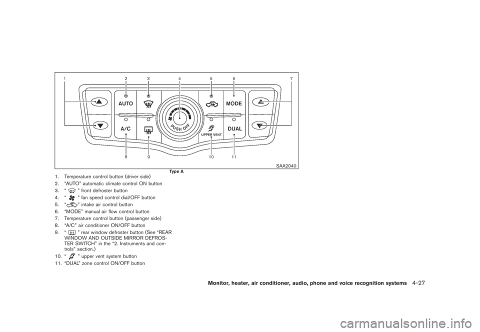
SAA2040Type A1. Temperature control button (driver side)
2. “AUTO” automatic climate control ON button
3. “
” front defroster button
4. “
” fan speed control dial/OFF button
5. “
” intake air control button
6. “MODE” manual air flow control button
7. Temperature control button (passenger side)
8. “A/C” air conditioner ON/OFF button
9. “
” rear window defroster button (See “REAR
WINDOW AND OUTSIDE MIRROR DEFROS-
TER SWITCH” in the “2. Instruments and con-
trols” section.)
10. “
” upper vent system button
11. “DUAL” zone control ON/OFF button
Monitor, heater, air conditioner, audio, phone and voice recognition systems4-27
Page 192 of 443
Black plate (190,1)
Model "Z51-D" EDITED: 2007/ 10/ 2
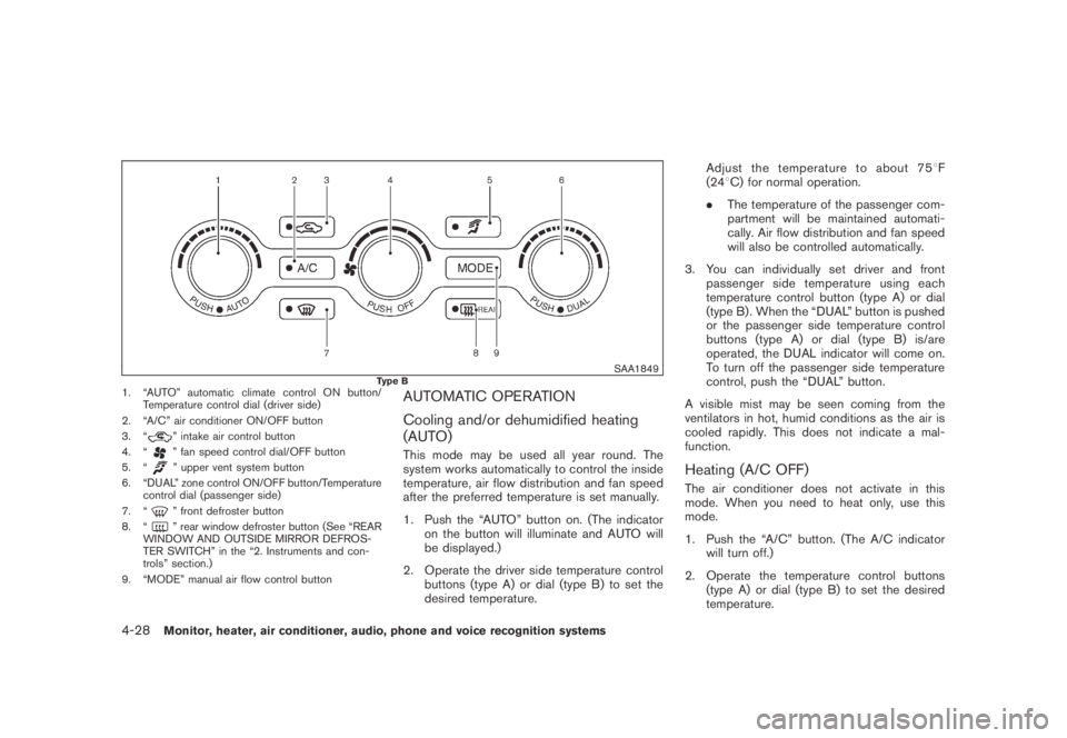
SAA1849Type B1. “AUTO” automatic climate control ON button/
Temperature control dial (driver side)
2. “A/C” air conditioner ON/OFF button
3. “
” intake air control button
4. “
” fan speed control dial/OFF button
5. “
” upper vent system button
6. “DUAL” zone control ON/OFF button/Temperature
control dial (passenger side)
7. “
” front defroster button
8. “
” rear window defroster button (See “REAR
WINDOW AND OUTSIDE MIRROR DEFROS-
TER SWITCH” in the “2. Instruments and con-
trols” section.)
9. “MODE” manual air flow control button
AUTOMATIC OPERATION
Cooling and/or dehumidified heating
(AUTO)
This mode may be used all year round. The
system works automatically to control the inside
temperature, air flow distribution and fan speed
after the preferred temperature is set manually.
1. Push the “AUTO” button on. (The indicator
on the button will illuminate and AUTO will
be displayed.)
2. Operate the driver side temperature control
buttons (type A) or dial (type B) to set the
desired temperature.Adjust the temperature to about 758F
(248C) for normal operation.
.The temperature of the passenger com-
partment will be maintained automati-
cally. Air flow distribution and fan speed
will also be controlled automatically.
3. You can individually set driver and front
passenger side temperature using each
temperature control button (type A) or dial
(type B) . When the “DUAL” button is pushed
or the passenger side temperature control
buttons (type A) or dial (type B) is/are
operated, the DUAL indicator will come on.
To turn off the passenger side temperature
control, push the “DUAL” button.
A visible mist may be seen coming from the
ventilators in hot, humid conditions as the air is
cooled rapidly. This does not indicate a mal-
function.
Heating (A/C OFF)
The air conditioner does not activate in this
mode. When you need to heat only, use this
mode.
1. Push the “A/C” button. (The A/C indicator
will turn off.)
2. Operate the temperature control buttons
(type A) or dial (type B) to set the desired
temperature.
4-28Monitor, heater, air conditioner, audio, phone and voice recognition systems
Page 324 of 443
Black plate (324,1)
Model "Z51-D" EDITED: 2007/ 10/ 2
NOTE:
The key port does not charge the key
battery. If you see the low battery indicator
in the dot matrix liquid crystal display,
replace the battery as soon as possible.
(See “BATTERY REPLACEMENT” in the “8.
Maintenance and do-it-yourself” section.)
CAUTION
.Never place anything except the key
in the key port. Doing so may cause
damage to the equipment.
.Make sure the key is in the correct
direction when inserting it to the
key port. The engine may not start if
it is in the incorrect direction.
.Remove the key from the key port
after the ignition switch is pushed to
the OFF position..Make sure the area around the vehicle is
clear.
.Check fluid levels such as engine oil, cool-
ant, brake fluid and window washer fluid as
frequently as possible, or at least whenever
you refuel.
.Check that all windows and lights are clean.
.Visually inspect tires for their appearance
and condition. Also check tires for proper
inflation.
.Lock all doors.
.Position seat and adjust head restraints.
.Adjust inside and outside mirrors.
.Fasten seat belts and ask all passengers to
do likewise.
.Check the operation of warning lights when
the ignition switch is pushed to the ON
position. (See “WARNING/INDICATOR
LIGHTS AND AUDIBLE REMINDERS” in
the “2. Instruments and controls” section.)1. Apply the parking brake.
2. Move the selector lever to the P (Park) or N
(Neutral) position. (P is recommended.)
The starter is designed not to operate unless
the selector lever is in either of the above
positions.
3. Insert the key into the key port. (Without the
Intelligent Key System)
Push the ignition switch to the ON position.
Depress the brake pedal and push the
ignition switch to start the engine.
To start the engine immediately, push and
release the ignition switch while depressing
the brake pedal with the ignition switch in
any position.
.If the engine is very hard to start in
extremely cold weather or when restart-
ing, depress the accelerator pedal a little
(approximately 1/3 to the floor) and
while holding, crank the engine. Release
the accelerator pedal when the engine
starts.
.If the engine is very hard to start
because it is flooded, depress the
accelerator pedal all the way to the floor
and hold it. Push the ignition switch to
the ON position to start cranking the
engine. After 5 or 6 seconds, stop
BEFORE STARTING THE ENGINE STARTING THE ENGINE
5-12Starting and driving
Page 391 of 443
Black plate (393,1)
Model "Z51-D" EDITED: 2007/ 10/ 2
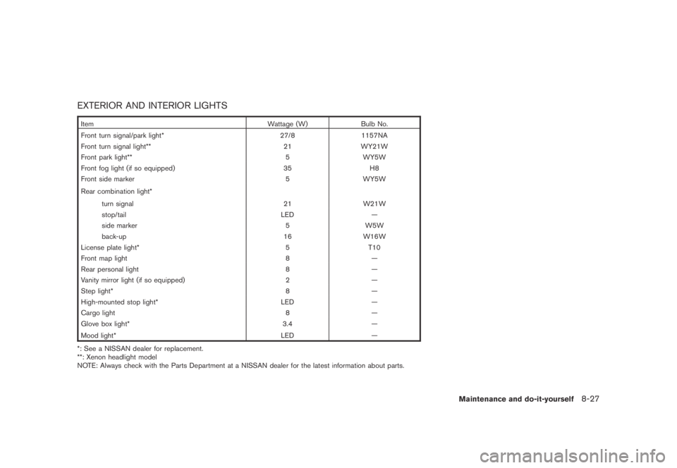
EXTERIOR AND INTERIOR LIGHTS
Item Wattage (W) Bulb No.
Front turn signal/park light* 27/8 1157NA
Front turn signal light** 21 WY21W
Front park light** 5 WY5W
Front fog light (if so equipped) 35 H8
Front side marker 5 WY5W
Rear combination light*
turn signal 21 W21W
stop/tail LED —
side marker 5 W5W
back-up 16 W16W
License plate light* 5 T10
Front map light 8 —
Rear personal light 8 —
Vanity mirror light (if so equipped) 2 —
Step light* 8 —
High-mounted stop light* LED —
Cargo light 8 —
Glove box light* 3.4 —
Mood light* LED
—
*: See a NISSAN dealer for replacement.
**: Xenon headlight model
NOTE: Always check with the Parts Department at a NISSAN dealer for the latest information about parts.
Maintenance and do-it-yourself8-27
Page 393 of 443
Black plate (395,1)
Model "Z51-D" EDITED: 2007/ 10/ 2
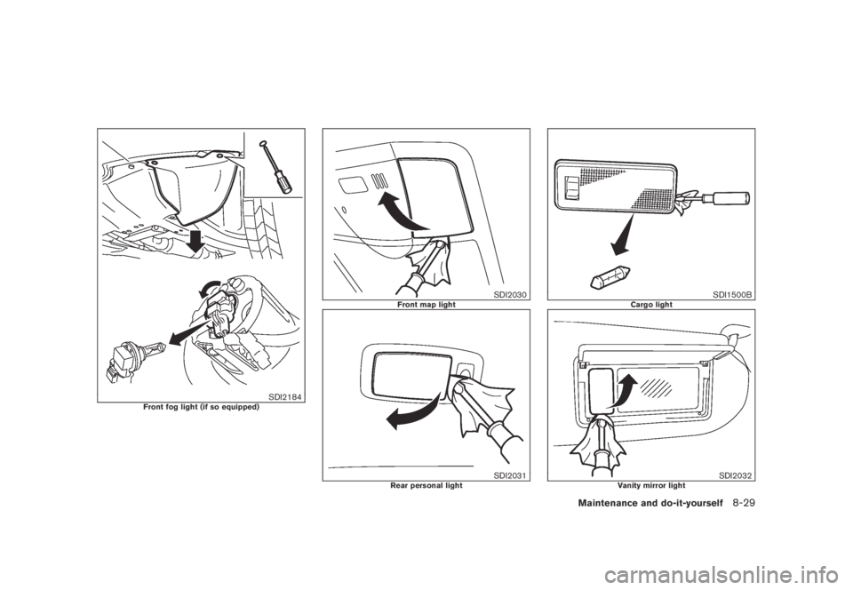
SDI2184Front fog light (if so equipped)
SDI2030Front map light
SDI2031Rear personal light
SDI1500BCargo light
SDI2032Vanity mirror light
Maintenance and do-it-yourself8-29