Page 2446 of 4331
EC-1090< SERVICE INFOMATION >
[MR TYPE 2]
TROUBLE DIAGNOSIS
Overall Sequence
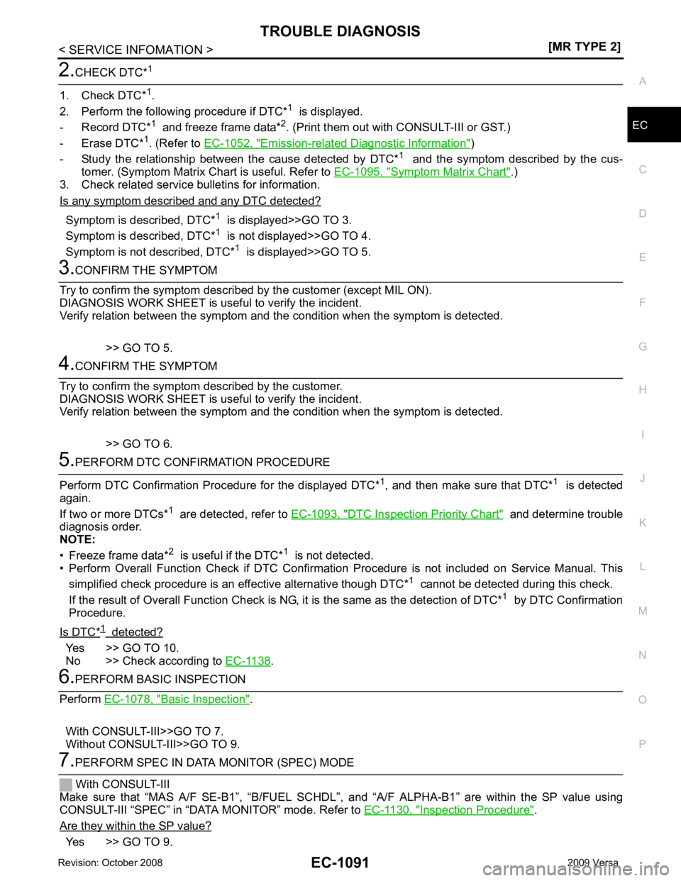
Detailed Flow 1.
GET INFORMATION FOR SYMPTOM
Get the detailed information from the customer about the symptom (the condition and the environment when
the incident/malfunction occurred) us ing the "DIAGNOSTIC WORKSHEET".
>> GO TO 2. PBIB3456E
Page 2447 of 4331

EC
NP
O Emission-related Diagnostic Information " )
- Study the relationship betw een the cause detected by DTC* 1
and the symptom described by the cus-
tomer. (Symptom Matrix Chart is useful. Refer to EC-1095, " Symptom Matrix Chart " .)
3. Check related service bulletins for information.
Is any symptom described and any DTC detected? Symptom is described, DTC*
1
is displayed>>GO TO 3.
Symptom is described, DTC* 1
is not displayed>>GO TO 4.
Symptom is not described, DTC* 1
is displayed>>GO TO 5. DTC Inspection Priority Chart " and determine trouble
diagnosis order.
NOTE:
• Freeze frame data* 2
is useful if the DTC* 1
is not detected.
• Perform Overall Function Check if DTC Confirmation Procedure is not included on Service Manual. This
simplified check procedure is an effective alternative though DTC* 1
cannot be detected during this check.
If the result of Overall Function Check is NG, it is the same as the detection of DTC* 1
by DTC Confirmation
Procedure.
Is DTC* Yes >> GO TO 10.
No >> Check according to EC-1138 .
Basic Inspection " .
With CONSULT-III>>GO TO 7.
Without CONSULT-III>>GO TO 9. Inspection Procedure " .
Are they within the SP value? Yes >> GO TO 9.
Page 2449 of 4331
![NISSAN LATIO 2009 Service Repair Manual TROUBLE DIAGNOSIS
EC-1093
< SERVICE INFOMATION >
[MR TYPE 2] C
D E
F
G H
I
J
K L
M A EC
NP
O
There are many operating conditions
that lead to the malfunction of
engine components. A good gra NISSAN LATIO 2009 Service Repair Manual TROUBLE DIAGNOSIS
EC-1093
< SERVICE INFOMATION >
[MR TYPE 2] C
D E
F
G H
I
J
K L
M A EC
NP
O
There are many operating conditions
that lead to the malfunction of
engine components. A good gra](/manual-img/5/57359/w960_57359-2448.png)
TROUBLE DIAGNOSIS
EC-1093
< SERVICE INFOMATION >
[MR TYPE 2] C
D E
F
G H
I
J
K L
M A EC
NP
O
There are many operating conditions
that lead to the malfunction of
engine components. A good grasp of such conditions can make trou-
bleshooting faster and more accurate.
In general, each customer feels differently about an incident. It is
important to fully understand the symptoms or conditions for a cus-
tomer complaint.
Utilize a diagnostic worksheet as shown in the following "Worksheet
Sample" in order to organize all the information for troubleshooting.
Some conditions may cause the MI L to come on steady or blink and
DTC to be detected. Examples:
• Vehicle ran out of fuel, which caused the engine to misfire.
• Fuel filler cap was left off or incorrectly screwed on, allowing fuel to evaporate into the atmosphere.
Worksheet Sample
DTC Inspection Priority Chart INFOID:0000000004499938
If some DTCs are displayed at the same time, perform inspections one by one based on the following priority
chart. SEF907L
MTBL0017
Page 2456 of 4331
EC-1100< SERVICE INFOMATION >
[MR TYPE 2]
TROUBLE DIAGNOSIS
Engine Control Comp onent Parts Location INFOID:0000000004499941
1. Ignition coil (with power transistor) and spark plug 2. Intake valve timing control solenoid
valve 3. Refrigerant pressure sensor
4. Knock sensor 5. Fuel injector 6. Cooling fan motor
7. Camshaft position sensor (PHASE) 8. IPDM E/R 9. ECM
10. Mass air flow sensor (with intake air temperature sensor) 11. Engine coolant temperature sensor 12. Electric throttle control actuator
(with built-in throttle position sensor,
throttle control motor)
13. EVAP canister purge volume control solenoid valve PBIB3261E
Page 2457 of 4331
TROUBLE DIAGNOSIS
EC-1101
< SERVICE INFOMATION >
[MR TYPE 2] C
D E
F
G H
I
J
K L
M A EC
NP
O
: Vehicle front
1. Mass air flow sensor (with intake air temperature sensor) 2. Engine coolant temperature sensor 3. Electric throttle control actuator
(with built in throttle position sensor,
throttle control motor)
4. PCV valve 5. Cooling fan motor 6. Resistor
7. Refrigerant pressure sensor BBIA0724E
Page 2458 of 4331
EC-1102< SERVICE INFOMATION >
[MR TYPE 2]
TROUBLE DIAGNOSIS
: Vehicle front
1. Intake valve timing control solenoid valve 2. Knock sensor 3. IPDM E/R
4. Fuel pump fuse (15A) 5. Fuel level sensor unit and fuel pump harness connector (view with in-
spection hole cover removed) 6. Fuel level sensor unit and fuel pump
7. Fuel pressure regulator 8. Fuel level sensor 9. Fuel tank temperature sensor
10. Ignition coil (with power transistor) and spark plug 11. Fuel injector BBIA0725E
Page 2459 of 4331
TROUBLE DIAGNOSIS
EC-1103
< SERVICE INFOMATION >
[MR TYPE 2] C
D E
F
G H
I
J
K L
M A EC
NP
O
:
Vehicle front
1. Crankshaft position sensor (POS) 2. Camshaft position sensor (PHASE) 3. EVAP canister purge volume control solenoid valve
4. EVAP service port 5. ECM harness connector 6. ECM
7. Stop lamp switch 8. Accelerator pedal position sensor BBIA0727E
Page 2460 of 4331
EC-1104< SERVICE INFOMATION >
[MR TYPE 2]
TROUBLE DIAGNOSIS
: Vehicle front
1. Air fuel ratio (A/F) sensor 1 2. Three way catalyst (Manifold) 3. Heated oxygen sensor 2
4. Three way catalyst (Under floor) 5. Muffler 6. Air fuel ratio (A/F) sensor 1 harness connector
7. Heated oxygen sensor 2 harness connector BBIA0726E