2009 NISSAN LATIO oil filter
[x] Cancel search: oil filterPage 3765 of 4331
MA-22< SERVICE INFORMATION >
ENGINE MAINTENANCE (HR16DE)
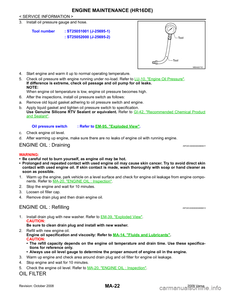
3. Install oil pressure gauge and hose.
4. Start engine and warm it up to normal operating temperature.
5. Check oil pressure with engine running under no-load. Refer to LU-10, " Engine Oil Pressure " .
If difference is extreme, check oil passage and oil pump for oil leaks.
NOTE:
When engine oil temperature is low, engine oil pressure becomes high.
6. After the inspections, install oil pressure switch as follows:
a. Remove old liquid gasket adhering to oil pressure switch and engine.
b. Apply liquid gasket and tighten oil pressure switch to specification. Use Genuine Silicone RTV Sealant or equivalent. Refer to GI-42, " Recommended Chemical Product
and Sealant " .
c. Check engine oil level.
d. After warming up engine, make sure there are no leaks of engine oil with running engine.
ENGINE OIL : Draining INFOID:0000000004806011
WARNING:
• Be careful not to burn yoursel f, as engine oil may be hot.
• Prolonged and repeated contact with used engine oil may cause ski n cancer. Try to avoid direct skin
contact with used engine oil. If skin contact is made, wash thoroughly with soap or hand cleaner as
soon as possible.
1. Warm up the engine, park vehicle on a level surface and check for engine oil leakage from engine compo- nents. Refer to MA-20, " ENGINE OIL : Inspection " .
2. Stop the engine and wait for 10 minutes.
3. Loosen oil filler cap.
4. Remove drain plug and then drain engine oil.
ENGINE OIL : Refilling INFOID:0000000004806012
1. Install drain plug with new washer. Refer to EM-39, " Exploded View " .
CAUTION:
Be sure to clean drain plug and install with new washer.
2. Refill with new engine oil. Engine oil specification and viscosity: Refer to MA-14, " Fluids and Lubricants " .
CAUTION:
• The refill capacity depends on the engine oi l temperature and drain time. Use these specifica-
tions for reference only.
• Always use oil level gauge to determine the pr oper amount of engine oil in the engine.
3. Warm up engine and check area around drain plug and oil filter for engine oil leakage.
4. Stop engine and wait for 10 minutes.
5. Check the engine oil level. Refer to MA-20, " ENGINE OIL : Inspection " .
OIL FILTER Tool number : ST25051001 (J-25695-1)
: ST25052000 (J-25695-2) WBIA0571E
Oil pressure switch : Refer to
EM-95, " Exploded View " .
Page 3766 of 4331

ENGINE MAINTENANCE (HR16DE)
MA-23
< SERVICE INFORMATION >
C
D E
F
G H
I
J
K
M A
B MA
N
O P
OIL FILTER : Remova
l and Installation INFOID:0000000004806013
REMOVAL 1. Remove oil filter using Tool (A). • : Front
WARNING:
• Be careful not to get burned when engine and engine oil
may be hot.
CAUTION:
• Oil filter is provided with relief valve. Use Genuine
NISSAN Oil Filter or equivalent.
• When removing, prepare a s hop cloth to absorb any
engine oil leakage or spillage.
• Do not spill engine oil on drive belt.
• Completely wipe off any engine oil that spills on engine and vehicle.
INSTALLATION 1. Remove foreign materials adhering to the oil filter installation surface.
2. Apply new engine oil to the oil seal contact surface of new oil fil- ter.
3. Screw oil filter manually until it touches the installation surface,
then tighten it by 2/3 turn. Or tighten to specification.
INSPECTION AFTER INSTALLATION 1. Check the engine oil level. Refer to MA-20, " ENGINE OIL : Inspection " .
2. Start engine, and make sure there are no leaks of engine oil.
3. Stop engine and wait for 10 minutes.
4. Check the engine oil level and adjust as necessary. Refer to MA-20, " ENGINE OIL : Inspection " .
SPARK PLUG (HR16DE) Tool number : KV10115801 (J-38956) PBIC3818E
SMA010
Oil filter: : 17.7 N·m (1.8 kg-m, 13 ft-lb)
SMA229B
Page 3773 of 4331
MA-30< SERVICE INFORMATION >
ENGINE MAINTENANCE (MR18DE)
AIR CLEANER FILTER : Changing Air Cleaner Filter INFOID:0000000004685431
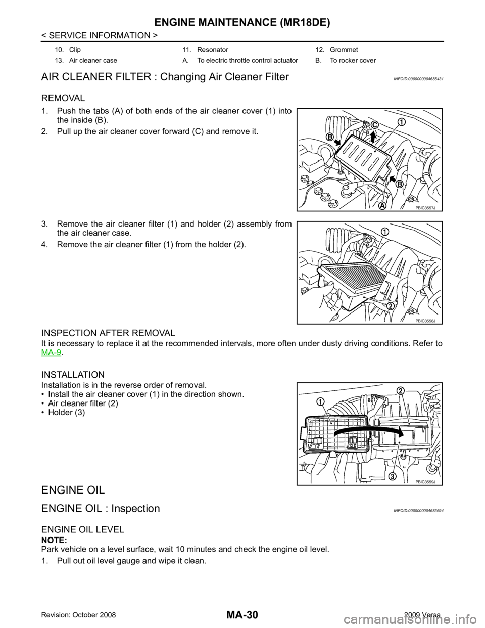
REMOVAL
1. Push the tabs (A) of both ends of the air cleaner cover (1) into the inside (B).
2. Pull up the air cleaner cover forward (C) and remove it.
3. Remove the air cleaner filter (1) and holder (2) assembly from the air cleaner case.
4. Remove the air cleaner filter (1) from the holder (2).
INSPECTION AFTER REMOVAL
It is necessary to replace it at the recommended interv als, more often under dusty driving conditions. Refer to
MA-9 .
INSTALLATION
Installation is in the reverse order of removal.
• Install the air cleaner cover (1) in the direction shown.
• Air cleaner filter (2)
• Holder (3)
ENGINE OIL
ENGINE OIL : Inspection INFOID:0000000004683694
ENGINE OIL LEVEL
NOTE:
Park vehicle on a level surface, wait 10 minutes and check the engine oil level.
1. Pull out oil level gauge and wipe it clean. 10. Clip 11. Resonator 12. Grommet
13. Air cleaner case A. To electric throttle control actuator B. To rocker cover PBIC3557J
PBIC3558J
PBIC3559J
Page 3774 of 4331
ENGINE MAINTENANCE (MR18DE)
MA-31
< SERVICE INFORMATION >
C
D E
F
G H
I
J
K
M A
B MA
N
O P
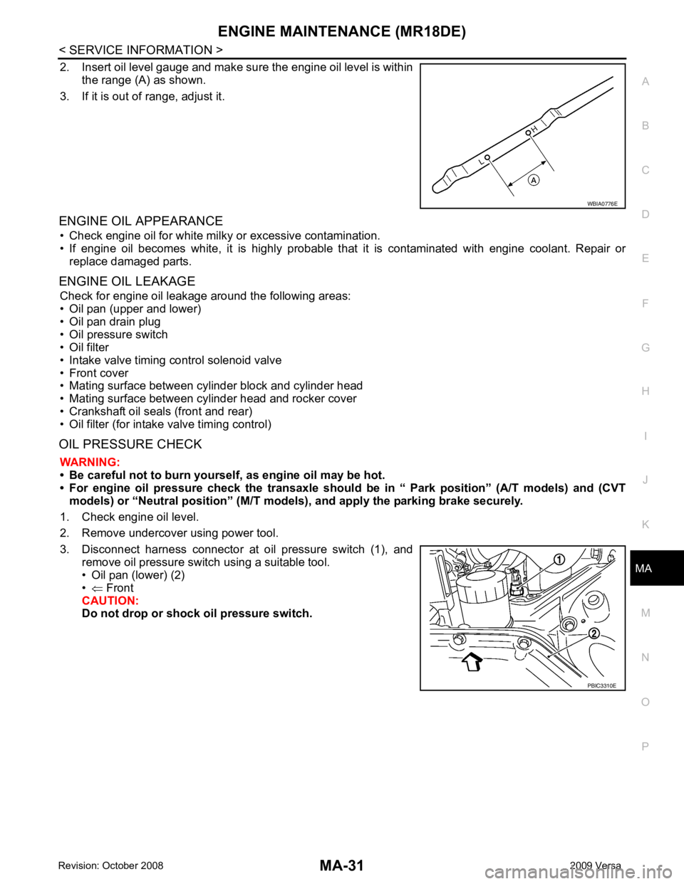
2. Insert oil level gauge and make sure the engine oil level is within
the range (A) as shown.
3. If it is out of range, adjust it.
ENGINE OIL APPEARANCE • Check engine oil for white milky or excessive contamination.
• If engine oil becomes white, it is highly probable t hat it is contaminated with engine coolant. Repair or
replace damaged parts.
ENGINE OIL LEAKAGE Check for engine oil leakage around the following areas:
• Oil pan (upper and lower)
• Oil pan drain plug
• Oil pressure switch
• Oil filter
• Intake valve timing control solenoid valve
• Front cover
• Mating surface between cylinder block and cylinder head
• Mating surface between cylinder head and rocker cover
• Crankshaft oil seals (front and rear)
• Oil filter (for intake valve timing control)
OIL PRESSURE CHECK WARNING:
• Be careful not to burn yoursel f, as engine oil may be hot.
• For engine oil pressure check the transaxle should be in “ Park position” (A/T models) and (CVT
models) or “Neutral position” (M/T mode ls), and apply the parking brake securely.
1. Check engine oil level.
2. Remove undercover using power tool.
3. Disconnect harness connector at oil pressure switch (1), and remove oil pressure switch using a suitable tool.
• Oil pan (lower) (2)
• ⇐ Front
CAUTION:
Do not drop or shock oil pressure switch. WBIA0776E
PBIC3310E
Page 3776 of 4331
ENGINE MAINTENANCE (MR18DE)
MA-33
< SERVICE INFORMATION >
C
D E
F
G H
I
J
K
M A
B MA
N
O P
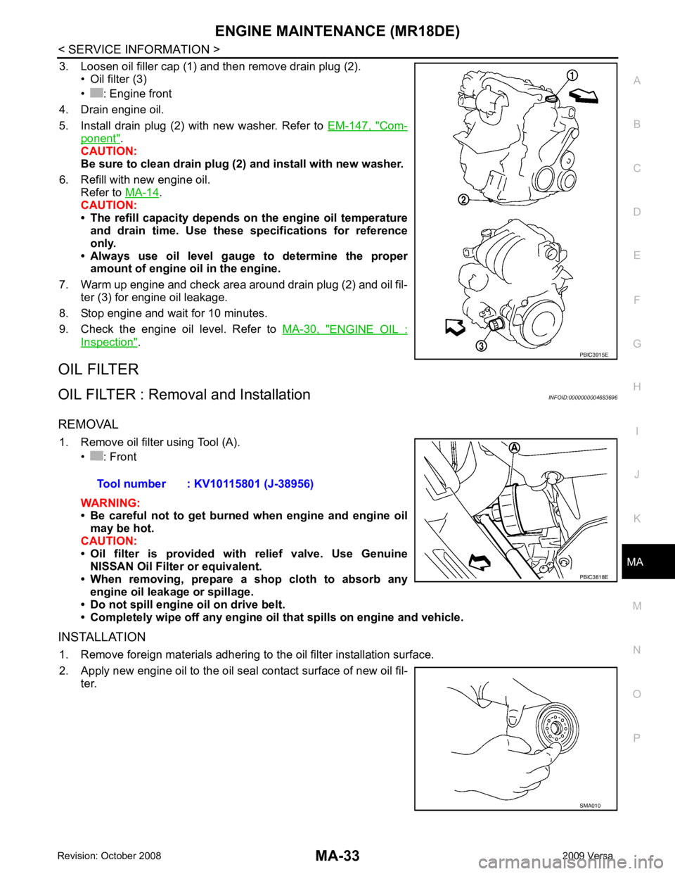
3. Loosen oil filler cap (1) and then remove drain plug (2).
• Oil filter (3)
• : Engine front
4. Drain engine oil.
5. Install drain plug (2) with new washer. Refer to EM-147, " Com-
ponent " .
CAUTION:
Be sure to clean drain plug (2 ) and install with new washer.
6. Refill with new engine oil. Refer to MA-14 .
CAUTION:
• The refill capacity depends on the engine oil temperature
and drain time. Use these sp ecifications for reference
only.
• Always use oil level gauge to determine the proper amount of engine oil in the engine.
7. Warm up engine and check area around drain plug (2) and oil fil- ter (3) for engine oil leakage.
8. Stop engine and wait for 10 minutes.
9. Check the engine oil level. Refer to MA-30, " ENGINE OIL :
Inspection " .
OIL FILTER
OIL FILTER : Remova l and Installation INFOID:0000000004683696
REMOVAL 1. Remove oil filter using Tool (A). • : Front
WARNING:
• Be careful not to get burned when engine and engine oil
may be hot.
CAUTION:
• Oil filter is provided with relief valve. Use Genuine NISSAN Oil Filter or equivalent.
• When removing, prepare a s hop cloth to absorb any
engine oil leakage or spillage.
• Do not spill engine oil on drive belt.
• Completely wipe off any engine oil that spills on engine and vehicle.
INSTALLATION 1. Remove foreign materials adhering to the oil filter installation surface.
2. Apply new engine oil to the oil seal contact surface of new oil fil- ter. PBIC3915E
Tool number : KV10115801 (J-38956)
PBIC3818E
SMA010
Page 3777 of 4331
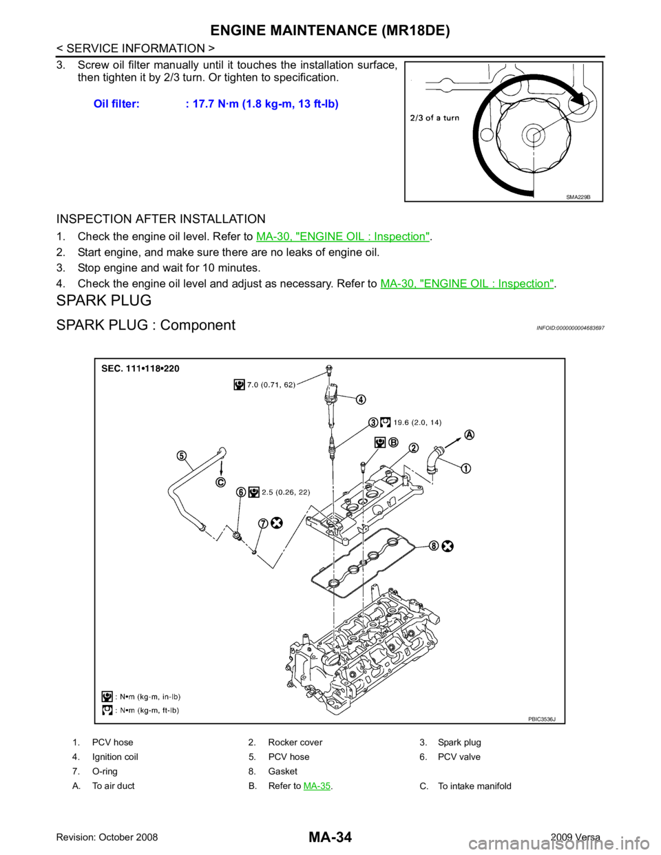
MA-34< SERVICE INFORMATION >
ENGINE MAINTENANCE (MR18DE)
3. Screw oil filter manually until it touches the installation surface,
then tighten it by 2/3 turn. Or tighten to specification.
INSPECTION AFTER INSTALLATION
1. Check the engine oil level. Refer to MA-30, " ENGINE OIL : Inspection " .
2. Start engine, and make sure there are no leaks of engine oil.
3. Stop engine and wait for 10 minutes.
4. Check the engine oil level and adjust as necessary. Refer to MA-30, " ENGINE OIL : Inspection " .
SPARK PLUG
SPARK PLUG : Component INFOID:0000000004683697
Oil filter: : 17.7 N·m (1.8 kg-m, 13 ft-lb) SMA229B
1. PCV hose 2. Rocker cover 3. Spark plug
4. Ignition coil 5. PCV hose 6. PCV valve
7. O-ring 8. Gasket
A. To air duct B. Refer to MA-35 . C. To intake manifold PBIC3536J
Page 3886 of 4331
MTC
N
O P
CONTENTS
MANUAL AIR CONDITIONER
SERVICE INFORMATION .. ..........................3
PRECAUTIONS .............................................. .....3
Precaution for Supplemental Restraint System
(SRS) "AIR BAG" and "SEAT BELT PRE-TEN-
SIONER" ............................................................. ......
3
Precaution Necessary fo r Steering Wheel Rota-
tion After Battery Disconnect ............................... ......
3
Precaution for Procedure without Cowl Top Cover ......4
Precaution for Working with HFC-134a (R-134a) ......4
General Refrigerant Precaution .......................... ......4
Oil Precaution ...................................................... ......5
Precaution for Refrigeran t Connection ......................5
Precaution for Service of Compressor ................ ......7
Precaution for Service Equipment ....................... ......8
Precaution for Leak Detection Dye ..................... ......9
PREPARATION .............................................. ....11
HFC-134a (R-134a) Service Tool and Equipment ....11
Commercial Service Tool .................................... ....13
REFRIGERATION SYSTEM .......................... ....15
Refrigerant Cycle ................................................ ....15
Refrigerant System Protec tion ................................15
Component Part Location ................................... ....16
OIL .................................................................. ....17
Maintenance of Oil Quantity in Compressor ....... ....17
AIR CONDITIONER CONTROL ..................... ....19
Control Operation ................................................ ....19
Discharge Air Flow .............................................. ....20
System Description ............................................. ....20
TROUBLE DIAGNOSIS ................................. ....22
CONSULT-II Function (BCM) .............................. ....22
How to Perform Trouble Diagnosis for Quick and
Accurate Repair ........... ...........................................
22
Component Parts and Harness Connector Loca-
tion ...................................................................... ....
23
Schematic ........................................................... ....25
Wiring Diagram - Heater - ................................... ....26 Wiring Diagram - A/C,M - ....................................
....27
Operational Check ............................................... ....30
Mode Door ........................................................... ....31
Air Mix Door ......................................................... ....32
Intake Door .......................................................... ....33
Front Blower Motor Circuit .......................................33
Magnet Clutch Circuit (If Equipped) ..................... ....37
Insufficient Cooling .............................................. ....45
Insufficient Heating .............................................. ....52
Noise ................................................................... ....53
CONTROLLER .................................................. 55
Removal and Installation ..................................... ....55
Disassembly and Assembly ................................. ....56
THERMO CONTROL AMPLIFIER .................... 57
Removal and Installation ..................................... ....57
A/C UNIT ASSEMBLY ...................................... 58
Removal and Installation ..................................... ....58
Disassembly and Assembly ................................. ....60
BLOWER MOTOR ............................................ 62
Removal and Installation ..................................... ....62
INTAKE DOOR .................................................. 63
Intake Door Cable Adjustment ............................. ....63
AIR MIX DOOR ................................................. 64
Air Mix Door Cable Adjustment ........................... ....64
MODE DOOR .................................................... 65
Mode Door Cable Adjustment ............................. ....65
BLOWER FAN RESISTOR ............................... 66
Removal and Installation ..................................... ....66
HEATER CORE ................................................. 67
Removal and Installation ..................................... ....67
AIR CONDITIONER FILTER ............................. 68
Removal and Installation ..................................... ....68
Page 3970 of 4331
MTC
N
O P
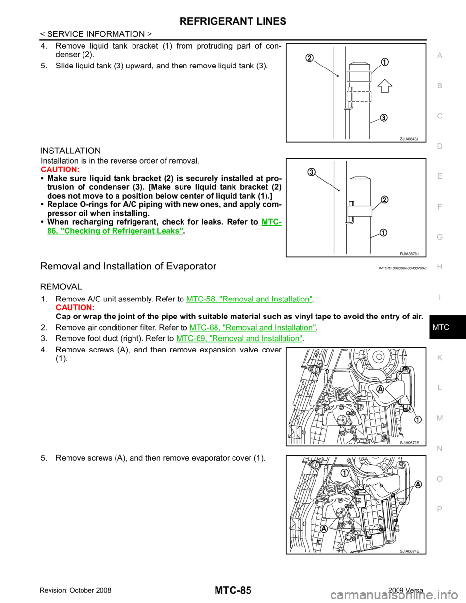
4. Remove liquid tank bracket (1
) from protruding part of con-
denser (2).
5. Slide liquid tank (3) upward, and then remove liquid tank (3).
INSTALLATION Installation is in the reverse order of removal.
CAUTION:
• Make sure liquid tank bracket (2) is securely installed at pro-
trusion of condenser (3). [Make sure liquid tank bracket (2)
does not move to a position belo w center of liquid tank (1).]
• Replace O-rings for A/C piping with new ones, and apply com-
pressor oil when installing.
• When recharging refrigerant, check for leaks. Refer to MTC-86, " Checking of Refrigerant Leaks " .
Removal and Installation of Evaporator INFOID:0000000004307098
REMOVAL 1. Remove A/C unit assembly. Refer to MTC-58, " Removal and Installation " .
CAUTION:
Cap or wrap the joint of the pipe with suitable ma terial such as vinyl tape to avoid the entry of air.
2. Remove air conditioner filter. Refer to MTC-68, " Removal and Installation " .
3. Remove foot duct (right). Refer to MTC-69, " Removal and Installation " .
4. Remove screws (A), and then remove expansion valve cover (1).
5. Remove screws (A), and then remove evaporator cover (1). RJIA3879J