2009 NISSAN LATIO warning light
[x] Cancel search: warning lightPage 3662 of 4331

Preliminary Check " .
4. Check symptom and repair or repl ace the cause of the malfunction.
5. Do turn signal and hazard warning lamps operate no rmally? If YES, GO TO 6. If NO, GO TO 4.
6. INSPECTION END
Preliminary Check INFOID:0000000004306579
CHECK POWER SUPPLY AND GROUND CIRCUIT FOR BCM
Refer to BCS-15, " BCM Power Supply and Ground Circuit Inspection " .
CONSULT-III Function (BCM) INFOID:0000000004306580
Refer to LT-11, " CONSULT-III Function (BCM) " .
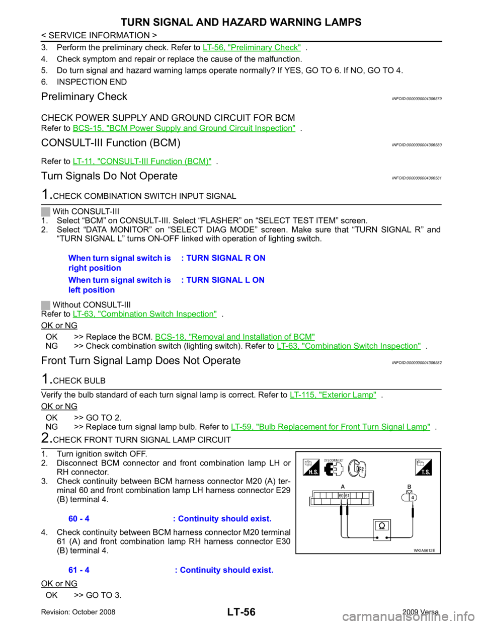
Turn Signals Do Not Operate INFOID:0000000004306581Combination Switch Inspection " .
OK or NG OK >> Replace the BCM.
BCS-18, " Removal and Installation of BCM "
NG >> Check combination switch (lighting switch). Refer to
LT-63, " Combination Switch Inspection " .
Front Turn Signal La mp Does Not Operate INFOID:0000000004306582 Exterior Lamp " .
OK or NG OK >> GO TO 2.
NG >> Replace turn signal lamp bulb. Refer to LT-59, " Bulb Replacement for Front Turn Signal Lamp " .
OK >> GO TO 3.When turn signal switch is
right position : TURN SIGNAL R ON
When turn signal switch is
left position : TURN SIGNAL L ON60 - 4 : Continuity should exist.
61 - 4 : Continuity should exist.
Page 4002 of 4331

PG
N
O P
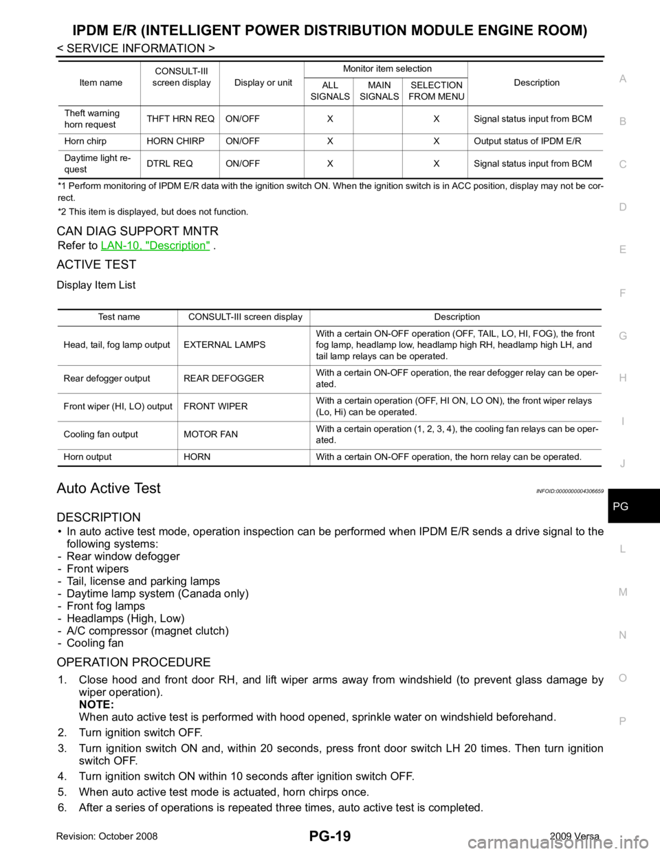
*1 Perform monitoring of IPDM E/R data with the ignition switch ON. When the ignition switch is in ACC position, display may no
t be cor-
rect.
*2 This item is displayed, but does not function.
CAN DIAG SUPPORT MNTR Refer to LAN-10, " Description " .
ACTIVE TEST
Display Item List
Auto Active Test INFOID:0000000004306659
DESCRIPTION • In auto active test mode, operation inspection can be performed when IPDM E/R sends a drive signal to the
following systems:
- Rear window defogger
- Front wipers
- Tail, license and parking lamps
- Daytime lamp system (Canada only)
- Front fog lamps
- Headlamps (High, Low)
- A/C compressor (magnet clutch)
- Cooling fan
OPERATION PROCEDURE 1. Close hood and front door RH, and lift wiper arms away from windshield (to prevent glass damage by
wiper operation).
NOTE:
When auto active test is performed with hood opened, sprinkle water on windshield beforehand.
2. Turn ignition switch OFF.
3. Turn ignition switch ON and, within 20 seconds, pre ss front door switch LH 20 times. Then turn ignition
switch OFF.
4. Turn ignition switch ON within 10 seconds after ignition switch OFF.
5. When auto active test mode is actuated, horn chirps once.
6. After a series of operations is repeated th ree times, auto active test is completed.
Theft warning
horn request THFT HRN REQ ON/OFF X X Signal status input from BCM
Horn chirp HORN CHIRP ON/OFF X X O utput status of IPDM E/R
Daytime light re-
quest DTRL REQ ON/OFF X X Signal
status input from BCM
Item name
CONSULT-III
screen display Display or unit Monitor item selection
Description
ALL
SIGNALS MAIN
SIGNALS SELECTION
FROM MENU Test name CONSULT-III screen display Description
Head, tail, fog lamp output EXTERNAL LAMPS With a certain ON-OFF operation (OFF, TAIL, LO, HI, FOG), the front
fog lamp, headlamp low, headlamp high RH, headlamp high LH, and
tail lamp relays can be operated.
Rear defogger output REAR DEFOGGER With a certain ON-OFF operation, the rear defogger relay can be oper-
ated.
Front wiper (HI, LO) output FRONT WIPER With a certain operation (OFF, HI ON, LO ON), the front wiper relays
(Lo, Hi) can be operated.
Cooling fan output MOTOR FAN With a certain operation (1, 2, 3, 4), the cooling fan relays can be oper-
ated.
Horn output HORN With a certain ON-OFF operation, the horn relay can be operated.
Page 4040 of 4331

PG
N
O P
Wiring Diagram Codes (Cell Codes)
INFOID:0000000004306667
Use the chart below to find out what each wiring diagram code stands for.
Refer to the wiring diagram code in the alphabetical index to find the location (page number) of each wiring
diagram. D4 D405 W/4 : Back door lock assembly C2 D413 B/1 : Rear window defogger (-)
D4 D406 W/2 : Back door request switch F3 D414 — : Body ground
E2 D407 W/2 : High mounted stop lamp Code Section Wiring Diagram Name
ABS BRC Anti-lock Brake System
A/C,M MTC Manual Air Conditioner
APPS1 EC Accelerator Pe dal Position Sensor
A/F EC Air Fuel Ratio Sensor 1
A/FH EC Air Fuel Ratio Sensor 1 Heater
APPS2 EC Accelerator Pe dal Position Sensor
APPS3 EC Accelerator Pe dal Position Sensor
ASC/BS EC ASCD Brake Switch
ASC/SW EC ASCD Steering Switch
ASCBOF EC ASCD Brake Switch
ASCIND EC ASCD Indicator
AT/IND DI A/T Indicator Lamp
AUDIO AV Audio
BACK/L LT Back-up Lamp
BA/FTS AT A/T Fluid Temperature Sensor and TCM Power Supply
B/DOOR BL Back Door Opener
BRK/SW EC Brake Switch
CAN AT CAN Communication Line
CAN CVT CAN Comm unication Line
CAN EC CAN Communication Line
CAN LAN CAN System
CHARGE SC Charging System
CHIME DI Warning Chime
COOL/F EC Cooling Fan Control
COMBSW LT Combination Switch
CVTIND DI CVT Indicator Lamp
D/LOCK BL Power Door Lock
DEF GW Rear Window Defogger
DTRL LT Headlamp - Wi th Daytime Light System
ECTS EC Engine Coolant Temperature Sensor
ENGSS AT Engine Speed Signal
EPS STC Electronic Controlled Power Steering
ETC1 EC Electric Throttle Control Function
ETC2 EC Throttle Control Motor Relay
ETC3 EC Throttle Control Motor
F/FOG LT Front Fog Lamp
F/PUMP EC Fuel Pump
FTS AT A/T Fluid Temperature Sensor
FTS CVT CVT Fluid Temperature Sensor Circuit
FTTS EC Fuel Tank Temperature Sensor
FUEL EC Fuel Ignition System Function
HEATER MTC Heater System
Page 4227 of 4331

SRS
N
O P
SPIRAL CABLE
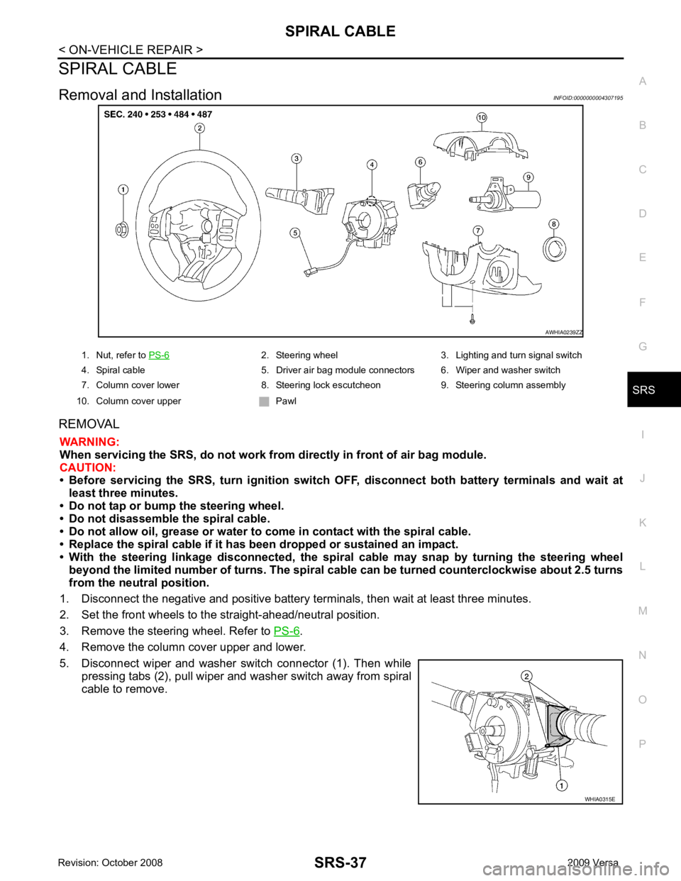
Removal and Installation INFOID:0000000004307195
REMOVAL WARNING:
When servicing the SRS, do not work from directly in front of air bag module.
CAUTION:
• Before servicing the SRS, turn ignition switch OFF, disconnect both battery terminals and wait at
least three minutes.
• Do not tap or bump the steering wheel.
• Do not disassemble the spiral cable.
• Do not allow oil, grease or water to co me in contact with the spiral cable.
• Replace the spiral cable if it has b een dropped or sustained an impact.
• With the steering linkage disconn ected, the spiral cable may snap by turning the steering wheel
beyond the limited number of turns. The spiral cable can be turned counterclockwise about 2.5 turns
from the neutral position.
1. Disconnect the negative and positive battery term inals, then wait at least three minutes.
2. Set the front wheels to the straight-ahead/neutral position.
3. Remove the steering wheel. Refer to PS-6 .
4. Remove the column cover upper and lower.
5. Disconnect wiper and washer switch connector (1). Then while pressing tabs (2), pull wiper and washer switch away from spiral
cable to remove. 2. Steering wheel 3. Lighting and turn signal switch
4. Spiral cable 5. Driver air bag module connectors 6. Wiper and washer switch
7. Column cover lower 8. Steering lock escutcheon 9. Steering column assembly
10. Column cover upper Pawl
Page 4241 of 4331

STC
N
O P
CONTENTS
STEERING CONTROL SYSTEM
EPS
SERVICE INFORMATION .. ..........................
2
PRECAUTIONS .............................................. .....2
Precaution for Supplemental Restraint System
(SRS) "AIR BAG" and "SEAT BELT PRE-TEN-
SIONER" ............................................................. ......
2
Precaution Necessary fo r Steering Wheel Rota-
tion After Battery Disconnect ............................... ......
2
Service Notice or Precau tion for EPS System ..........3
EPS SYSTEM ... .............................................. .....4
System Description ............................................. ......4
Schematic ........................................................... ......5
CAN Communication ........................................... ......5
TROUBLE DIAGNOSIS ................................. .....6
Fail-Safe Function ............................................... ......6
How to Perform Trouble Diagnosis ..................... ......6
Component Parts Location .................................. ......7
Wiring Diagram - EPS - ... ..........................................8
EPS Control Unit Input/O utput Signal Reference
Value ................................................................... ......
9 EPS Terminal and Reference Value ....................
....10
CONSULT-III Function ( EPS) ..................................11
Symptom Chart .................................................... ....13
TROUBLE DIAGNOSIS FOR SYSTEM ............ 14
DTC C1601 BATTERY VOLT .............................. ....14
DTC C1604 TORQUE SENSOR ......................... ....15
DTC C1606 EPS MOTOR ................................... ....16
DTC C1607 EEPROM ......................................... ....17
DTC C1608 CONTROL UNIT .............................. ....17
DTC C1609 CAN VHCL SPEED ......................... ....18
DTC C1610 CAN ENG RPM ............................... ....19
DTC U1000 CAN COMM CIRCUIT ..................... ....19
Component Inspection ......................................... ....19
TROUBLE DIAGNOSIS FOR SYMPTOMS ...... 21
EPS Warning Lamp Does Not Turn ON ..................21
EPS Warning Lamp Does Not Turn OFF ................21
Steering Wheel Turning Force Is Heavy or Light . ....22
Unbalance Steering Wheel Turning Force and Re-
turn Between Right and Left ................................ ....
23
Unbalance Steering Wheel Turning Force (Torque
Variation) ............................................................. ....
24
Page 4253 of 4331

STC
N
O P
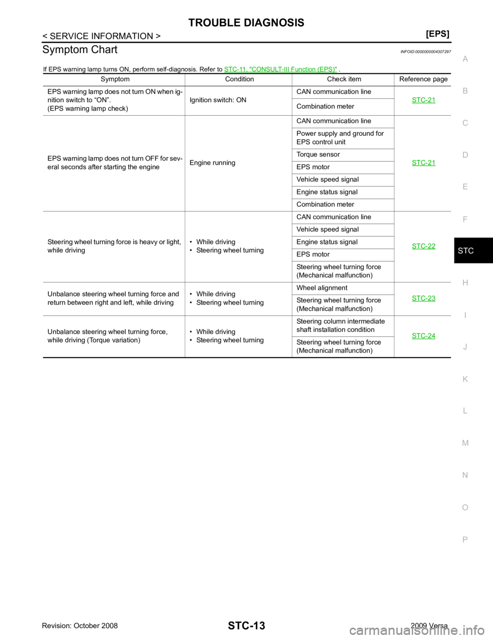
Symptom Chart
INFOID:0000000004307297
If EPS warning lamp turns ON, perform self-diagnosis. Refer to STC-11, " CONSULT-III Function (EPS) " .
Symptom Condition Check item Reference page
EPS warning lamp does not turn ON when ig-
nition switch to “ON”.
(EPS warning lamp check) Ignition switch: ONCAN communication line
STC-21 Combination meter
EPS warning lamp does not turn OFF for sev-
eral seconds after starting the engine Engine runningCAN communication line
STC-21 Power supply and ground for
EPS control unit
Torque sensor
EPS motor
Vehicle speed signal
Engine status signal
Combination meter
Steering wheel turning force is heavy or light,
while driving • While driving
• Steering wheel turning CAN communication line
STC-22 Vehicle speed signal
Engine status signal
EPS motor
Steering wheel turning force
(Mechanical malfunction)
Unbalance steering wheel turning force and
return between right and left, while driving • While driving
• Steering wheel turning Wheel alignment
STC-23 Steering wheel
turning force
(Mechanical malfunction)
Unbalance steering wheel turning force,
while driving (Torque variation) • While driving
• Steering wheel turning Steering column intermediate
shaft installation condition STC-24 Steering wheel
turning force
(Mechanical malfunction)