2009 MITSUBISHI ASX clock
[x] Cancel search: clockPage 286 of 368
l
Use the tyre sealant only at ambient tempera-
tures of -30 °C to + 60 °C.
l Effect an emergency repair without pulling
out the object (nail, screw, etc.) that is stuck
in the tyre.
l Do not use the tyre sealant if the tyre has
been damaged by being driven when insuffi-
ciently inflated (e.g. bumps, cuts, cracks etc.
on the tyre).
l Allow any tyre sealant seeping out of the
hole to dry, then pull off like a film.
l Wipe tyre sealant off the paintwork immedi-
ately with a damp cloth.
l Allow any tyre sealant in a damaged tyre to
dry out and dispose of it together with the tyre.
l Immediately change out of any clothes conta-
minated with the tyre sealant.
Before repairing a tyre, first stop your vehicle in a
safe, flat location. 1. Park the vehicle on level and stable ground.
2. Set the parking brake firmly.
3. On vehicles with M/T, stop the engine andmove the gearshift lever to the “R” (Reverse)
position.
On vehicles with CVT, move the selector lev-
er to the “P” (PARK) position and stop the en-
gine.
4. Turn on the hazard warning flashers and set up a warning triangle, flashing signal lamp,
etc., at an adequate distance from the vehi-
cle, and have all your passengers leave the ve-
hicle.
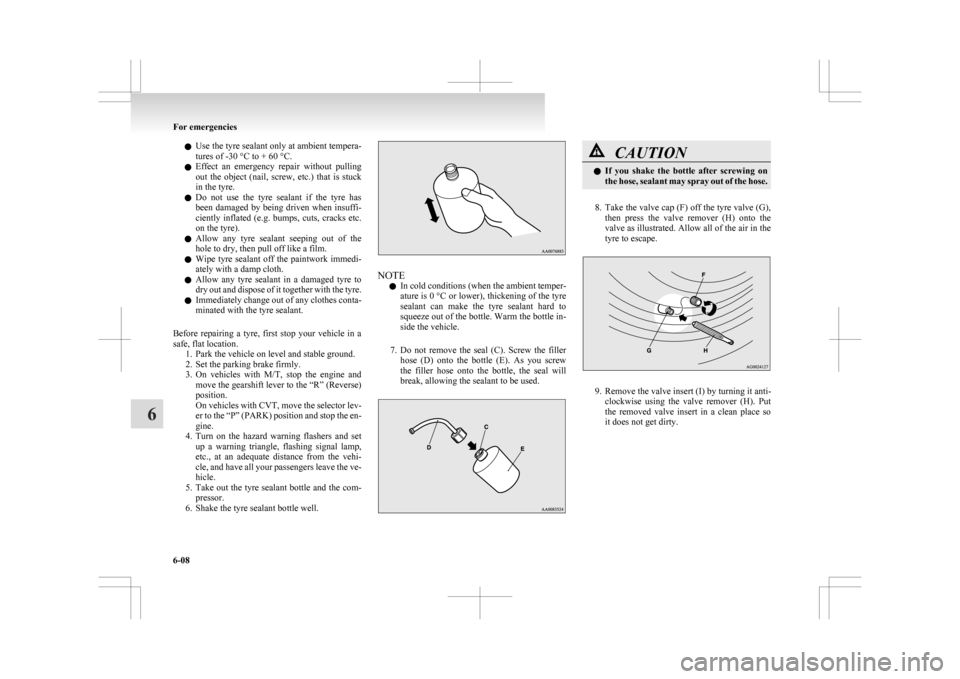
5. Take out the tyre sealant bottle and the com- pressor.
6. Shake the tyre sealant bottle well. NOTE
l In
cold conditions (when the ambient temper-
ature is 0 °C or lower), thickening of the tyre
sealant can make the tyre sealant hard to
squeeze out of the bottle. Warm the bottle in-
side the vehicle.
7. Do not remove the seal (C). Screw the filler hose (D) onto the bottle (E). As you screw
the filler hose onto the bottle, the seal will
break, allowing the sealant to be used. CAUTION
l
If
you shake the bottle after screwing on
the hose, sealant may spray out of the hose.
8. Take
the valve cap (F) off the tyre valve (G), then press the valve remover (H) onto the
valve as illustrated. Allow all of the air in the
tyre to escape. 9. Remove the valve insert (I) by turning it anti-
clockwise
using the valve remover (H). Put
the removed valve insert in a clean place so
it does not get dirty. For emergencies
6-08
6
Page 292 of 368
CAUTION
l
Do not install more than one temporary
spare wheel at the same time.
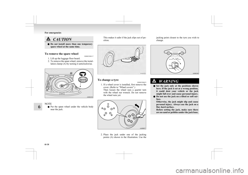
To remove the spare wheel E00803300117
1. Lift up the luggage floor board.
2. To
remove the spare wheel, remove the instal-
lation clamp (A) by turning it anticlockwise. NOTE
l Put
the spare wheel under the vehicle body
near the jack. This makes it safer if the jack slips out of po-
sition.
To change a tyre
E00803200653
1. If
a wheel cover is installed, first remove the
cover. (Refer to “Wheel covers”.)
Then loosen the wheel nuts a quarter turn
with the wheel nut wrench. Do not remove
the wheel nuts yet. 2. Place
the jack under one of the jacking
points (A) shown in the illustration. Use the jacking point closest to the tyre you wish to
change.
WARNING
l Set
the jack only at the positions shown
here. If the jack is set at a wrong position,
it could dent your vehicle or the jack
might fall over and cause personal injury.
l Do not use the jack on a tilted or soft sur-
face.
Otherwise, the jack might slip and cause
personal injury. Always use the jack on a
flat, hard surface.
Before setting the jack, make sure there
are no sand or pebbles under the jack base. For emergencies
6-14
6
Page 294 of 368
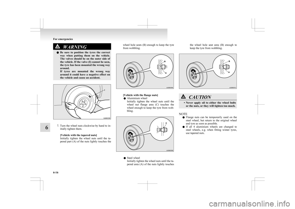
WARNING
l Be sure to position the tyres the correct
way when putting them on the vehicle.
The valves should be on the outer side of
the vehicle. If the valve (I) cannot be seen,
the tyre has been mounted the wrong way
around.
If tyres are mounted the wrong way
around it could have a negative effect on
the vehicle and cause an accident. 7. Turn
the wheel nuts clockwise by hand to in-
itially tighten them.
[Vehicle with the tapered nuts]
Initially tighten the wheel nuts until the ta-
pered part (A) of the nuts lightly touches the wheel hole seats (B) enough to keep the tyre
from wobbling.
[Vehicle with the flange nuts]
l Aluminium wheel
Initially
tighten the wheel nuts until the
wheel nut flange area (C) touches the
wheel enough to keep the tyre from wob-
bling. l
Steel wheel
Initially
tighten the wheel nuts until the ta-
pered area (A) of the nuts lightly touches the wheel hole seat area (B) enough to
keep the tyre from wobbling.
l
CAUTION
• Never
apply oil to either the wheel bolts
or the nuts, or they will tighten too much.
NOTE l Flange
nuts can be temporarily used on the
steel wheel, but return to the original wheel
and tyre as soon as possible.
l If all 4 aluminium wheels are changed to
steel wheels, e.g. when fitting winter tyres,
use tapered nuts. For emergencies
6-16
6
Page 295 of 368
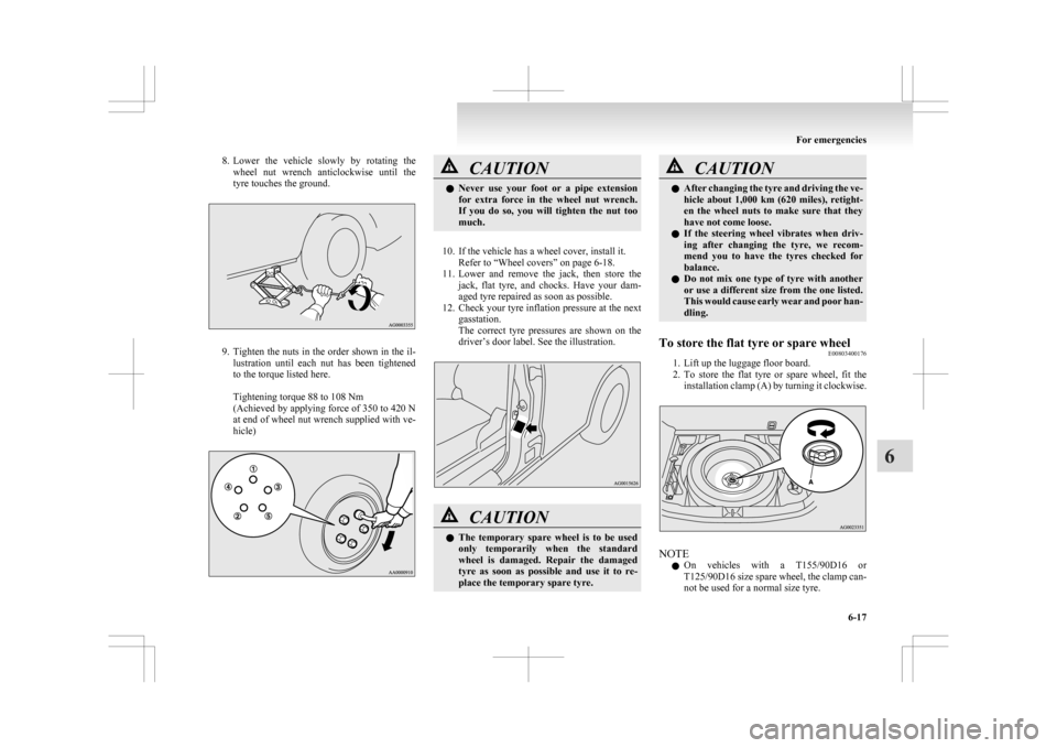
8. Lower the vehicle slowly by rotating the
wheel nut wrench anticlockwise until the
tyre touches the ground. 9. Tighten
the nuts in the order shown in the il-
lustration until each nut has been tightened
to the torque listed here.
Tightening torque 88 to 108 Nm
(Achieved by applying force of 350 to 420 N
at end of wheel nut wrench supplied with ve-
hicle) CAUTION
l
Never
use your foot or a pipe extension
for extra force in the wheel nut wrench.
If you do so, you will tighten the nut too
much.
10. If the vehicle has a wheel cover, install it. Refer to “Wheel covers” on page
6-18.
11. Lower and remove the jack, then store the jack, flat tyre, and chocks. Have your dam-
aged tyre repaired as soon as possible.
12. Check your tyre inflation pressure at the next gasstation.
The correct tyre pressures are shown on the
driver’s door label. See the illustration. CAUTION
l
The
temporary spare wheel is to be used
only temporarily when the standard
wheel is damaged. Repair the damaged
tyre as soon as possible and use it to re-
place the temporary spare tyre. CAUTION
l
After
changing the tyre and driving the ve-
hicle about 1,000 km (620 miles), retight-
en the wheel nuts to make sure that they
have not come loose.
l If the steering wheel vibrates when driv-
ing after changing the tyre, we recom-
mend you to have the tyres checked for
balance.
l Do not mix one type of tyre with another
or use a different size from the one listed.
This would cause early wear and poor han-
dling.
To store the flat tyre or spare wheel E00803400176
1. Lift up the luggage floor board.
2. To
store the flat tyre or spare wheel, fit the
installation clamp (A) by turning it clockwise. NOTE
l On
vehicles with a T155/90D16 or
T125/90D16 size spare wheel, the clamp can-
not be used for a normal size tyre. For emergencies
6-17 6
Page 331 of 368

Headlamps (low beam, except for vehi-
cles
with high intensity discharge head-
lamps) E01009300163
1. When replacing the bulb on the left side of
the vehicle in the case of diesel-powered ve-
hicles, remove the bolt (A) holding down the
relay box and move the relay box towards
the rear of the vehicle. *: Front of the vehicle 2. When replacing the bulb on the right side of
the vehicle in the case of diesel-powered ve-
hicles, remove the bolts (B) holding down
the reservoir tank and move the reservoir tank. *: Front of the vehicle
3. When
replacing the bulb on the right side of
the vehicle in the case of diesel-powered ve-
hicles, remove the clips (C) by prying with a
straight blade (or minus) screwdriver, and re-
move the side cover. *: Front of the vehicle4. Turn the cap (D) anticlockwise to remove it.
*: Front of the vehicle
5.
Turn the bulb (E) anticlockwise to remove it. *: Front of the vehicle Maintenance
8-25 8
Page 332 of 368

6. While holding down the tab (F), pull out the
socket (G). 7. To
install the bulb, perform the removal
steps in reverse. CAUTION
l
Handle
halogen lamp bulbs with care.
The gas inside halogen lamp bulbs is high-
ly pressurized, so dropping, knocking, or
scratching a halogen lamp bulb can cause
it to shatter.
l Never hold the halogen lamp bulb with a
bare hand, dirty glove, etc.
The oil from your hand could cause the
bulb to break the next time the head-
lamps are operated.
If the glass surface is dirty, it must be
cleaned with alcohol, paint thinner, etc.,
and refit it after drying it thoroughly. Headlamps (low beam, for vehicles
with high intensity discharge head-
lamps)
E01010100132
Do not attempt to disassemble or repair headlamps,
and do not attempt to replace their bulbs. WARNING
l A high voltage is present in the power cir-
cuit
and in the bulbs and bulb terminals.
To avoid the risk of an electric shock, con-
tact a MITSUBISHI MOTORS Author-
ized Service Point whenever repair or re-
placement is necessary. Headlamps (High-beam)
E01009400135
1. When
replacing the bulb on the left side of
the vehicle in the case of diesel-powered ve-
hicles, remove the bolt (A) holding down the
relay box and move the relay box towards
the rear of the vehicle. *: Front of the vehicle
2.
Turn the cap (B) anticlockwise to remove it. *: Front of the vehicleMaintenance
8-26
8
Page 333 of 368

3. Turn the bulb (C) anticlockwise to remove it.
*: Front of the vehicle
4. While holding down the tab (D), pull out the
socket (E). 5. To
install the bulb, perform the removal
steps in reverse. CAUTION
l
Handle
halogen lamp bulbs with care.
The gas inside halogen lamp bulbs is high-
ly pressurized, so dropping, knocking, or
scratching a halogen lamp bulb can cause
it to shatter.
l Never hold the halogen lamp bulb with a
bare hand, dirty glove, etc.
The oil from your hand could cause the
bulb to break the next time the head-
lamps are operated.
If the glass surface is dirty, it must be
cleaned with alcohol, paint thinner, etc.,
and refit it after drying it thoroughly. Position lamps
E01003700947
1. When
replacing the bulb on the left side of
the vehicle in the case of diesel-powered ve-
hicles, remove the bolt (A) holding down the
relay box and move the relay box towards
the rear of the vehicle. *: Front of the vehicle
2. When
replacing the bulb on the right side of
the vehicle in the case of diesel-powered ve-
hicles, remove the bolts (B) holding down
the reservoir tank and move the reservoir tank. *: Front of the vehicle Maintenance
8-27 8
Page 334 of 368
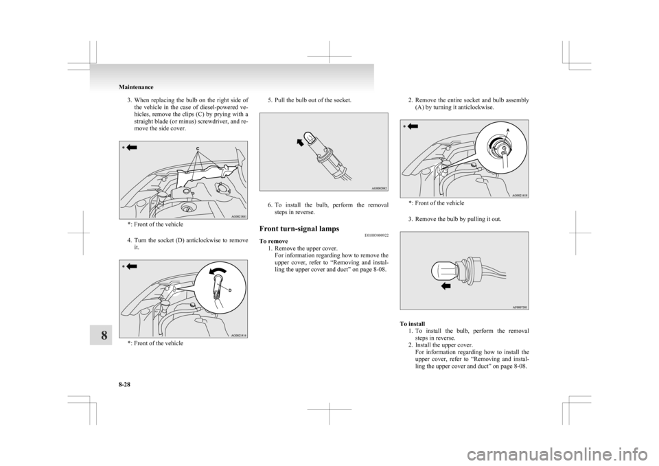
3. When replacing the bulb on the right side of
the vehicle in the case of diesel-powered ve-
hicles, remove the clips (C) by prying with a
straight blade (or minus) screwdriver, and re-
move the side cover. *: Front of the vehicle
4. Turn
the socket (D) anticlockwise to remove
it. *: Front of the vehicle 5. Pull the bulb out of the socket.
6. To
install the bulb, perform the removal
steps in reverse.
Front turn-signal lamps E01003800922
To remove
1.
Remove the upper cover.For information regarding how to remove the
upper cover, refer to “Removing and instal-
ling the upper cover and duct” on page 8-08. 2. Remove
the entire socket and bulb assembly
(A) by turning it anticlockwise. *: Front of the vehicle
3.
Remove the bulb by pulling it out. To install
1. To
install the bulb, perform the removal
steps in reverse.
2. Install the upper cover. For information regarding how to install the
upper cover, refer to “Removing and instal-
ling the upper cover and duct” on page 8-08. Maintenance
8-28
8