2009 MITSUBISHI ASX Oll level
[x] Cancel search: Oll levelPage 267 of 368
l
Do not connect to the USB input terminal
any device (hard disk, card reader, memory
reader, etc.) other than the connectable devi-
ces specified in the previous section.
The device and/or data may be damaged. If
any of these devices was connected by mis-
take, remove it after turning the ignition
switch to the “LOCK” position or putting the
operation mode in OFF.
File specifications E00762400017
You can play music files of the following specifica-
tions
that are saved in a USB memory device or oth-
er device supporting mass storage class. Item Condition
File format MP3, WMA, AAC,
WAV
Maximum number of
levels
(including the
root) Level 8
Number of folders 700
Number of files 65,535 Sun visors
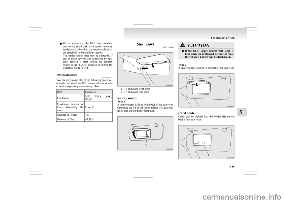
E00711201140 1- To eliminate front glare
2-
To eliminate side glare
Vanity mirror
Type 1
A vanity mirror is fitted to the back of the sun visor.
Operating the lid of the vanity mirror will automat-
ically turn on the mirror lamp (A). CAUTION
l
If
the lid of vanity mirror with lamp is
kept open for prolonged periods of time,
the vehicle’s battery will be discharged.
Type 2
A
vanity mirror is fitted to the back of the sun visor. Card holder
Cards
can be slipped into the holder (B) on the
back of the sun visor. For pleasant driving
5-59 5
Page 272 of 368
The brightness of the sunshade illumination can be
adjusted
to 3 different levels when the ignition
switch or the operation mode is in ON or ACC.
Each time you press the switch, the brightness
switches in sequence from high → middle → low
→ off → high.
NOTE
l The brightness can be adjusted even when
the ignition switch is in the “LOCK” posi-
tion or the operation mode is in OFF, provi-
ded that the sunshade illumination is turned
on.
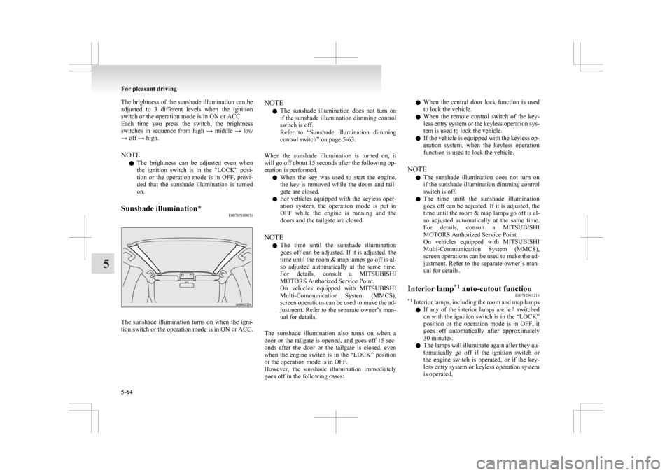
Sunshade illumination* E00765100031The sunshade illumination turns on when the igni-
tion
switch or the operation mode is in ON or ACC. NOTE
l The
sunshade illumination does not turn on
if the sunshade illumination dimming control
switch is off.
Refer to “Sunshade illumination dimming
control switch” on page 5-63.
When the sunshade illumination is turned on, it
will go off about 15 seconds after the following op-
eration is performed. l When the key was used to start the engine,
the key is removed while the doors and tail-
gate are closed.
l For vehicles equipped with the keyless oper-
ation system, the operation mode is put in
OFF while the engine is running and the
doors and the tailgate are closed.
NOTE l The time until the sunshade illumination
goes off can be adjusted. If it is adjusted, the
time until the room & map lamps go off is al-
so adjusted automatically at the same time.
For details, consult a MITSUBISHI
MOTORS Authorized Service Point.
On vehicles equipped with MITSUBISHI
Multi-Communication System (MMCS),
screen operations can be used to make the ad-
justment. Refer to the separate owner’s man-
ual for details.
The sunshade illumination also turns on when a
door or the tailgate is opened, and goes off 15 sec-
onds after the door or the tailgate is closed, even
when the engine switch is in the “LOCK” position
or the operation mode is in OFF.
However, the sunshade illumination immediately
goes off in the following cases: l
When the central door lock function is used
to lock the vehicle.
l When the remote control switch of the key-
less entry system or the keyless operation sys-
tem is used to lock the vehicle.
l If the vehicle is equipped with the keyless op-
eration system, when the keyless operation
function is used to lock the vehicle.
NOTE l The sunshade illumination does not turn on
if the sunshade illumination dimming control
switch is off.
l The time until the sunshade illumination
goes off can be adjusted. If it is adjusted, the
time until the room & map lamps go off is al-
so adjusted automatically at the same time.
For details, consult a MITSUBISHI
MOTORS Authorized Service Point.
On vehicles equipped with MITSUBISHI
Multi-Communication System (MMCS),
screen operations can be used to make the ad-
justment. Refer to the separate owner’s man-
ual for details.
Interior lamp *1
auto-cutout function
E00712901216
*1
Interior lamps, including the room and map lamps
l If any of the interior lamps are left switched
on with the ignition switch is in the “LOCK”
position or the operation mode is in OFF, it
goes off automatically after approximately
30 minutes.
l The lamps will illuminate again after they au-
tomatically go off if the ignition switch or
the engine switch is operated, or if the key-
less entry system or keyless operation system
is operated, For pleasant driving
5-64
5
Page 280 of 368
If the vehicle breaks down
E00800101108
If
the vehicle breaks down on the road, move it to
the shoulder and turn on the hazard warning flash-
ers and set up a warning triangle, flashing lamp, etc.
Refer to “Hazard warning flasher switch” on page
3-50.
If the engine stops/fails
Vehicle operation and control are affected if the en-
gine stops.
Before moving the vehicle to a safe area, be aware
of the following:
l The brake booster becomes inoperative and
the pedal effort will increase. Press down the
brake pedal harder than usual.
l Since the power steering system is no longer
operative, the steering wheel feels heavy
when turning it. Emergency starting
E00800502503
If
the engine cannot be started because the battery
is weak or dead, the battery from another vehicle
can be used with jumper cables to start the engine. WARNING
l To
start the engine using jumper cables
connected to another vehicle, perform the
correct procedures according to the in-
struction below. Incorrect procedures
could result in a fire or explosion or dam-
age to the vehicles. CAUTION
l
Do
not attempt to start the engine by pull-
ing or pushing the vehicle.
It could damage your vehicle.
l Always wear protective eye goggles when
working near the battery.
l Keep the battery out of the reach of chil-
dren.
1. Get
the vehicles close enough so the jumper cables can reach, but be sure the vehicles
aren’t touching each other. CAUTION
l
Check
the other vehicle. It must have a 12-
volt battery.
If the other system isn’t 12-volt, shorting
can damage both vehicles. 2. Turn
off all lamps, heater and other electrical
loads.
3. Set the parking brake firmly on each vehicle. Put an A/T, CVT in “P” (PARK) or a M/T in
“N” (Neutral).
4. Turn the ignition switch to the “LOCK” posi- tion or put the operation mode in OFF. WARNING
l Perform
step 4 on both vehicles before-
hand.
Make sure that the cables or your clothes
cannot be caught by the fan or drive belt.
Personal injury could result.
5. Make
sure battery electrolyte is at the proper level.
Refer to “Battery” on page 8-08. WARNING
l If
electrolyte fluid is not visible, or ap-
pears to be frozen, Do Not Attempt Jump
Starting!
A battery might rupture or explode if the
temperature is below the freezing point
or if it is not filled to the proper level.
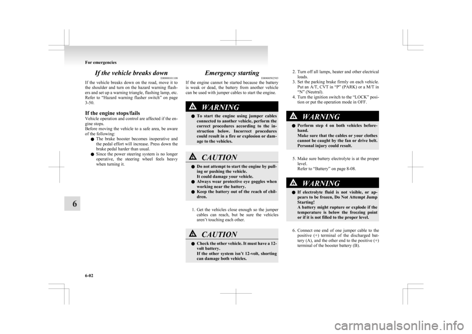
6. Connect
one end of one jumper cable to the positive (+) terminal of the discharged bat-
tery (A), and the other end to the positive (+)
terminal of the booster battery (B).
For emergencies
6-02
6
Page 290 of 368
l
A tyre in which puncture sealant has been
used should ideally be replaced with a new
one. If you wish to have such a tyre properly
repaired for reuse, please contact a
MITSUBISHI MOTORS Authorized Service
Point or another specialist. Note that a proper
repair is impossible following an emergency
repair if the puncture hole cannot be located.
l Wipe away any sealant that gets on the
wheel. Provided the valve is replaced with a
new one, the wheel can be reused.
l The manufacturer is unable to guarantee that
all tyre punctures can be repaired with the
tyre repair kit, in particular cuts or perfora-
tions with a diameter of more than 4 mm or
away from the tyre’s tread. The manufacturer
is not liable for damage sustained through im-
proper use of the tyre repair kit.
l The manufacturer is not liable for damage sus-
tained through re-use of any tyre in which
tyre sealant has been used. How to change a tyre
E00801202637
Before
changing a tyre, first stop your vehicle in a
safe, flat location. 1. Park the vehicle on level and stable ground,free of loose pebbles, etc.
2. Set the parking brake firmly.
3. On vehicles with M/T, stop the engine and move the gearshift lever to the “R” (Reverse)
position.
On vehicles with CVT, move the selector lev-
er to the “P” (PARK) position and stop the en-
gine.
4. Turn on the hazard warning flashers and set up a warning triangle, flashing signal lamp,
etc., at an adequate distance from the vehi-
cle, and have all your passengers leave the ve-
hicle.
NOTE l The warning triangle and flashing signal
lamp do not come with your vehicle. It is rec-
ommended that you keep one in the vehicle
for use if needed.
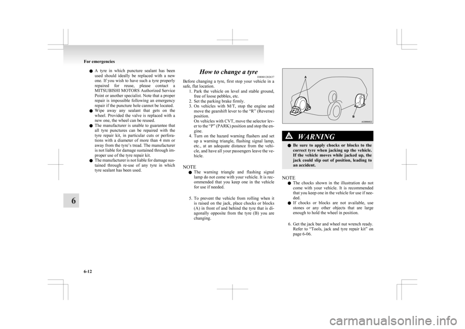
5. To prevent the vehicle from rolling when it is raised on the jack, place chocks or blocks
(A) in front of and behind the tyre that is di-
agonally opposite from the tyre (B) you are
changing. WARNING
l Be
sure to apply chocks or blocks to the
correct tyre when jacking up the vehicle.
If the vehicle moves while jacked up, the
jack could slip out of position, leading to
an accident.
NOTE l The
chocks shown in the illustration do not
come with your vehicle. It is recommended
that you keep one in the vehicle for use if nee-
ded.
l If chocks or blocks are not available, use
stones or any other objects that are large
enough to hold the wheel in position.
6. Get the jack bar and wheel nut wrench ready. Refer to “Tools, jack and tyre repair kit” on
page 6-06. For emergencies
6-12
6
Page 311 of 368
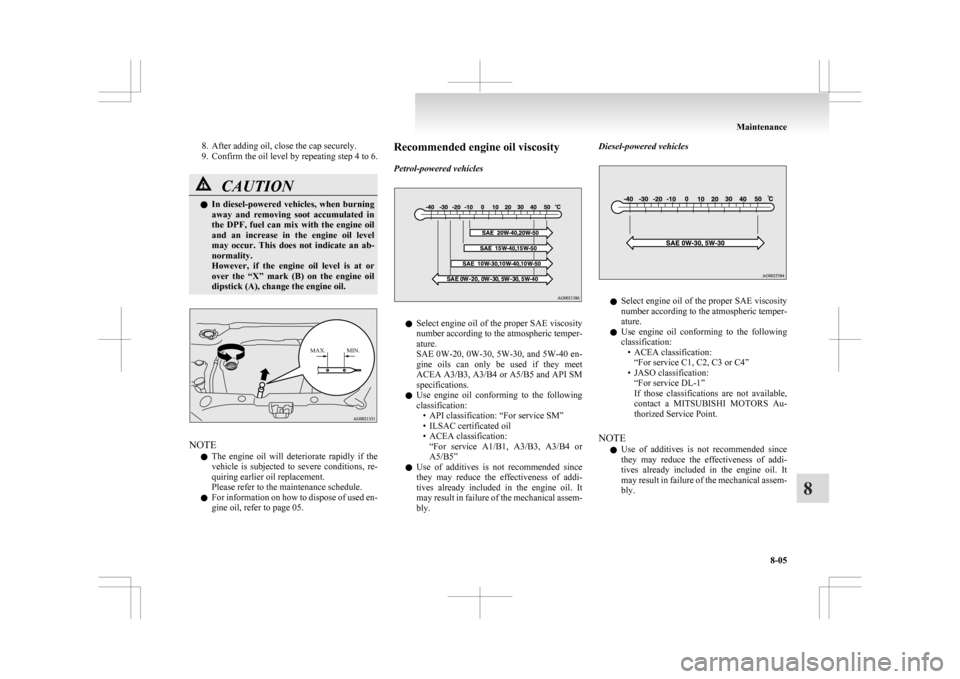
8. After adding oil, close the cap securely.
9.
Confirm the oil level by repeating step 4 to 6. CAUTION
l
In
diesel-powered vehicles, when burning
away and removing soot accumulated in
the DPF, fuel can mix with the engine oil
and an increase in the engine oil level
may occur. This does not indicate an ab-
normality.
However, if the engine oil level is at or
over the “X” mark (B) on the engine oil
dipstick (A), change the engine oil.
MAX. MIN. NOTE
l The
engine oil will deteriorate rapidly if the
vehicle is subjected to severe conditions, re-
quiring earlier oil replacement.
Please refer to the maintenance schedule.
l For information on how to dispose of used en-
gine oil, refer to page 05. Recommended engine oil viscosity
Petrol-powered vehicles
l
Select
engine oil of the proper SAE viscosity
number according to the atmospheric temper-
ature.
SAE 0W-20, 0W-30, 5W-30, and 5W-40 en-
gine oils can only be used if they meet
ACEA A3/B3, A3/B4 or A5/B5 and API SM
specifications.
l Use engine oil conforming to the following
classification:
• API classification: “For service SM”
• ILSAC certificated oil
• ACEA classification:“For service A1/B1, A3/B3, A3/B4 or
A5/B5”
l Use of additives is not recommended since
they may reduce the effectiveness of addi-
tives already included in the engine oil. It
may result in failure of the mechanical assem-
bly. Diesel-powered vehicles
l
Select
engine oil of the proper SAE viscosity
number according to the atmospheric temper-
ature.
l Use engine oil conforming to the following
classification:
• ACEA classification:“For service C1, C2, C3 or C4”
• JASO classification: “For service DL-1”
If those classifications are not available,
contact a MITSUBISHI MOTORS Au-
thorized Service Point.
NOTE l Use of additives is not recommended since
they may reduce the effectiveness of addi-
tives already included in the engine oil. It
may result in failure of the mechanical assem-
bly. Maintenance
8-05 8
Page 358 of 368

Used engine oils safety instructions and disposal
information 05
Exterior and interior lamp operation
8-17
F Fluid capacities and lubricants 9-14
Fluid
Automatic transmission fluid
9-14
Brake fluid 8-07,9-14
Clutch fluid 8-07
CVT fluid 9-14
Engine coolant 8-06,9-14
Power steering fluid 9-14
Twin Clutch SST fluid 9-14
Washer fluid 8-07,9-14
For cold and snowy weather 8-17
Front fog lamps Bulb capacity 8-24
Replacement 8-29
Switch 3-50
Front room lamp Bulb capacity 8-24
Front seat 2-03
Front turn-signal lamps Bulb capacity 8-24
Replacement 8-28
Fuel consumption 9-13
Fuel Filling the fuel tank 03
Fuel selection 02
Modification/alterations to the electrical or fuel
systems 05
Tank capacity 03
Fuses 8-18
Fusible links 8-18 GGeneral maintenance 8-17
General vehicle data
9-04
Genuine parts 05
Glove box lamp Bulb capacity 8-24
H Hazard warning flasher switch 3-50
Hazard warning indication lamps
3-40
Head restraints 2-07
Headlamp levelling switch 3-48
Headlamp washer switch 3-56
Headlamps Bulb capacity 8-23
Headlamp flasher 3-47
Replacement 8-25,8-26
Switch 3-44
Heated mirror 4-10
Heated seats 2-06
Heater 5-03
High-mounted stop lamp Bulb capacity 8-24
Replacement 8-33
Hill start assist 4-35
Hinges and latches lubrication 8-17
Horn switch 3-57
I If the vehicle breaks down 6-02
Ignition switch 4-11
Indication lamps
3-40
Information screen display 3-42
Inside rear-view mirror 4-08
Inside tailgate release 1-27 Inspection and maintenance following rough road
operation 4-33
Instruments 3-02
Interior lamps 5-62
Map lamps 5-63
J Jack 6-06
Storage 6-06
Jump starting (Emergency starting)
6-02
K Key slot 1-17
Keyless entry system 1-04,1-18
Keyless operation system 1-07
Keys 1-02
L Labeling 9-02
Lamp monitor buzzer
3-46
Leakage (Fuel, engine coolant, oil and exhaust
gas) 8-17
Licence plate lamps Bulb capacity 8-24
Replacement 8-33
Link System 5-41
Lubricants 9-14
Luggage hooks 5-70
Luggage room lamp 5-63 Bulb capacity 8-24
M Making a luggage compartment 2-08
Manual transmission 4-21
Map lamps 5-62,5-63Alphabetical index
2