2009 MITSUBISHI ASX towing
[x] Cancel search: towingPage 201 of 368

NOTE
l The
buzzer may sound lower than the normal
warning sound when the reversing sensor sys-
tem is receiving ultrasonic noise from other
sources, but this is not a malfunction. The buz-
zer will stop sounding and the system will re-
turn to normal operation after the noise is no
longer received.
To operate E00615700493
To operate the system, move the gearshift lever or
selector
lever to the “R” position while the ignition
switch or the operation mode is in ON. To stop the
operation, push the “SONAR” switch. NOTE
l Only
when the gearshift lever or selector lev-
er is in the “R” position, the reversing sensor
system can be operated or be stopped by us-
ing the “SONAR” switch.
The reversing sensor system operation indication
lamp (A) will turn off when the system has stopped
operating. It will flash in case there is a malfunction in the sys-
tem.
For details, refer to “Reversing sensor system
operation indication lamp” on page 4-50. To return the system to the operating state, push
the
“SONAR” switch again. When the system re-
turns to the operating state, the buzzer sounds once
and the indication lamp illuminates.
NOTE
l The reversing sensor system operation indica-
tion lamp blinks once when the ignition
switch is turned to the “ON” position or the
operation mode is put in ON.
The warning buzzer sounds when the system de-
tects an obstacle during operation.
NOTE l After pushing the “SONAR” switch, revers-
ing sensor system operation differs accord-
ing to the detection area setting. • Setting when towing bar is not equipped
When
the gearshift lever or selector lever
is moved to the “R” position, the revers-
ing sensor system will operate even if cor-
ner sensor operation was stopped by push-
ing the “SONAR” switch.
• Setting when towing bar is equipped When reversing sensor system operation
was stopped by pushing the “SONAR”
switch, the reversing sensor system will
not operate until the engine has been stop-
ped even if the gearshift lever or selector
lever is moved to the “R” position.
To resume reversing sensor system opera-
tion, push the “SONAR” switch or stop
and restart the engine, and then move the
gearshift lever or selector lever to the “R”
position.
Warning for obstacles
If there is an obstacle behind the vehicle, a warning
buzzer sounds to indicate the distance between the
vehicle and the obstacle.
Corner sensor Vehicle to obstacle dis-
tance Warning sound cycle
Approx. 60 to 40 cm Intermittent
Approx. 40 to 20 cm Fast intermittent
Within approx. 20 cm Continuous Starting and driving
4-49 4
Page 202 of 368

Back sensor (vehicles without a towing bar)
Vehicle to obstacle dis-
tance Warning sound cycle
Approx. 150 to 80 cm Intermittent Approx. 80 to 40 cm Fast intermittent
Within approx. 40 cm Continuous Back sensor (vehicles with a towing bar)
Vehicle to obstacle dis-
tance Warning sound cycle
Approx. 150 to 100 cm Intermittent Approx. 100 to 60 cm Fast intermittentWithin approx. 60 cm Continuous CAUTION
l
The distances given are to be used for ref-
erence
only, as errors may be caused by
various factors, such as temperature, hu-
midity, or the shape of the obstacles.
Changing the detection areas E00615800045
The detection areas can be changed as follows:
Vehicles with a towing bar
While
the operation of the system is stopped at the
“SONAR” switch, push the “SONAR” switch ap-
proximately 3 seconds or more, and release it. The
buzzer sounds twice to indicate that the detection
area has been changed. Vehicles without a towing bar
While
the operation of the system is stopped at the
“SONAR” switch, push the “SONAR” switch ap-
proximately 3 seconds or more, and release it. The
buzzer sounds once to indicate that the detection
area has been changed.
NOTE
l The detection area will not change if you
keep the “SONAR” switch pushed for
10 seconds or more.
Reversing sensor system operation in-
dication lamp E00615900222
In case there is a malfunction in the reversing sen-
sor
system, the reversing sensor system operation
indication lamp will blink and the warning buzzer
will sound for approximately 5 seconds. Even after
the buzzer has stopped sounding, the indication
lamp will continue flashing until the system reverts
to the normal state. Have the vehicle inspected at a
MITSUBISHI MOTORS Authorized Service Point. Rear-view camera*
E00618400172
The
rear-view camera is a system that shows the
view behind the vehicle on a screen in the centre
panel. CAUTION
l
The
rear-view camera is an assistance sys-
tem that enables the driver to check for
obstacles behind the vehicle. Its range of
view is limited, so you should not overly
depend on it. Please drive just as careful-
ly as you would if the vehicle did not have
the rear-view camera.
l Be sure to visually confirm safety around
the vehicle with your own eyes. Do not de-
pend entirely on the rear-view camera.
Range of view of rear-view camera
The
range of view of the rear-view camera is limi-
ted to the area shown in the illustrations. It cannot
show both sides and the lower part of the rear bump-
er, etc.
When reversing, be sure to visually confirm safety
around the vehicle. Starting and driving
4-50
4
Page 206 of 368

NOTE
l To
prevent wind noise or reduction in fuel
economy, remove the roof carrier when not
in use.
l Remove the roof carrier before using an auto-
matic car wash.
l Be sure that adequate clearance is main-
tained for raising the tailgate when installing
a roof carrier. Trailer towing
E00610000459
In
order to tow a trailer with your vehicle, have a
trailer towing device that meets all relevant regula-
tions in your area, mounted consult a
MITSUBISHI MOTORS Authorized Service Point.
The regulations concerning the towing of a trailer
may differ from country to country. You are ad-
vised to obey the regulations in each area. CAUTION
l
Danger of Accident!
A
towing bar should be fitted according
to MITSUBISHI MOTORS guidelines.
Maximum towable weight with brake
and maximum trailer-nose weight
Never
exceed the maximum towable weight with
brake and the maximum trailer-nose weight as lis-
ted in the specifications.
(Refer to page 9-07.)
If you tow a trailer at an altitude of more than
1,000 m above sea-level, reduce your weight by
10 % of the gross combination weight for every in-
crease of 1,000 m above sea-level, as the engine out-
put is lowered owing to decrease in atmospheric
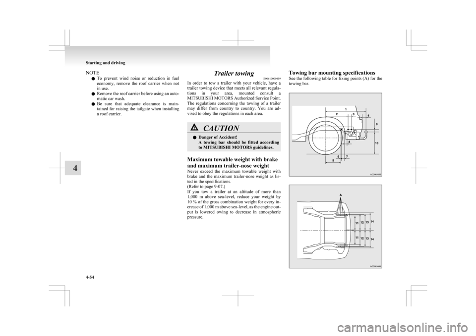
pressure. Towing bar mounting specifications
See
the following table for fixing points (A) for the
towing bar. Starting and driving
4-54
4
Page 279 of 368

If the vehicle breaks down
............................................................ 6-02
Emergency starting ....................................................................... 6-02
Engine overheating ....................................................................... 6-04
Tools, jack and tyre repair kit ....................................................... 6-06
How to change a tyre .................................................................... 6-12
Towing.......................................................................................... 6-19
Operation under adverse driving conditions .................................6-22For emergencies
6
Page 284 of 368

Tools, jack and tyre repair kit
E00800901278
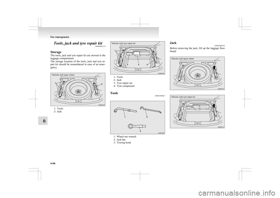
Storage
The
tools, jack and tyre repair kit are stowed in the
luggage compartment.
The storage location of the tools, jack and tyre re-
pair kit should be remembered in case of an emer-
gency.
Vehicles with spare wheel 1- Tools
2-
Jack
Vehicles with tyre repair kit 1- Tools
2-
Jack
3- Tyre repair set
4- Tyre compressor
Tools E00801900627 1- Wheel nut wrench
2-
Jack bar
3- Towing hook Jack
E00802000478
Before
removing the jack, lift up the luggage floor
board.
Vehicles with spare wheel
Vehicles with tyre repair kit For emergencies
6-06
6
Page 297 of 368

Towing
E00801503187
If your vehicle needs to be towed
If
you need to tow your vehicle, we recommend
that you contact a MITSUBISHI MOTORS Author-
ized Service Point or tow truck company.
In the following cases, transport the vehicle using a
tow truck.
l The engine runs but the vehicle does not
move or abnormal noise is produced.
l Inspection of the vehicle’s underside reveals
that oil or some other fluid is leaking.
If a wheel gets stuck in a ditch, do not try to tow
the vehicle.
Please contact your MITSUBISHI MOTORS Au-
thorized Service Point or a commercial tow truck
service for assistance.
Only when you cannot receive a towing service
from a MITSUBISHI MOTORS Authorized Serv-
ice Point or commercial tow truck service, tow
your vehicle carefully in accordance with the in-
structions given in “Emergency towing” in this part. The regulations concerning towing may differ from
country
to country. It is recommended that you
obey the regulations of the area where you are driv-
ing your vehicle.
Do not tow 4WD vehicles, or 2WD vehicles with CVT, with
this style.
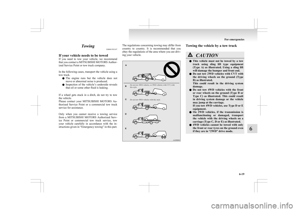
Do not tow 4WD vehicles with this style. Towing the vehicle by a tow truck
CAUTION
l
This
vehicle must not be towed by a tow
truck using sling lift type equipment
(Type A) as illustrated. Using a sling lift
will damage the bumper and front end.
l Do not tow 2WD vehicles with CVT with
the driving wheels on the ground (Type
B) as illustrated.
This could result in the driving system
damage.
l Do not tow 4WD vehicles with the front
or rear wheels on the ground (Type B or
Type C) as illustrated. This could result
in driving system damage or the vehicle
may jump at the carriage.
If you tow 4WD vehicles, use Type D or E
equipment.
l On 2WD vehicles, if the transmission is
malfunctioning or damaged, transport
the vehicle with the driving wheels on a
carriage (Type C, D or E) as illustrated.
l 4WD vehicles cannot be towed with only
the front or rear tyres on the ground even
if they are in “2WD” drive mode. For emergencies
6-19 6
Page 298 of 368
![MITSUBISHI ASX 2009 1.G Owners Manual CAUTION
l
[For 2WD vehicles equipped with the Ac-
tive Stability Control (ASC)]
If the vehicle is towed with the ignition
switch in the “ON” position or the opera-
tion mode in ON and MITSUBISHI ASX 2009 1.G Owners Manual CAUTION
l
[For 2WD vehicles equipped with the Ac-
tive Stability Control (ASC)]
If the vehicle is towed with the ignition
switch in the “ON” position or the opera-
tion mode in ON and](/manual-img/19/7566/w960_7566-297.png)
CAUTION
l
[For 2WD vehicles equipped with the Ac-
tive Stability Control (ASC)]
If the vehicle is towed with the ignition
switch in the “ON” position or the opera-
tion mode in ON and only the front
wheels or only the rear wheels raised off
the ground (Type B or C), the ASC may
operate, resulting in an accident.
When towing the vehicle with the rear
wheels raised, turn the ignition switch to
the “ACC” position or put the operation
mode in ACC.
When towing the vehicle with the front
wheels raised, keep the ignition switch or
the operation mode as follows.
[Except for vehicles equipped with key-
less operation system]
The ignition switch is in “LOCK” or
“ACC” position.
[Vehicles with keyless operation system]
The operation mode is in OFF or ACC.
Towing with rear wheels off the ground (Type B)
Place
the gearshift lever in the “N” (Neutral) posi-
tion.
Turn the ignition switch to the “ACC” position or
put the operation mode in ACC and secure the steer-
ing wheel in a straight-ahead position with a rope
or tiedown strap. Never place the ignition switch in
the “LOCK” position or put the operation mode in
OFF when towing.
Towing with front wheels off the ground (Type C)
Release the parking brake. Place the gearshift lever in the “N” (Neutral) posi-
tion
(M/T) or the selector lever in the “N” (NEU-
TRAL) position (CVT).
Emergency towing
If towing service is not available in an emergency,
your vehicle may be temporarily towed by a rope
secured to the towing hook.
If your vehicle is to be towed by another vehicle or
if your vehicle tows another vehicle, pay careful at-
tention to the following points:
If your vehicle is to be towed by another vehicle
1. The front towing hook (A) is located asshown in the illustration. Secure the tow rope
to the front towing hook. NOTE
l Do
not use the tie-down hooks (B) for tow-
ing. These hooks are provided only for the
purpose of transporting the vehicle itself.
Using any part other than the designated tow-
ing hook (A) could result in damage to vehi-
cle body. l
Using
a wire rope or metal chain can result
in damage to the vehicle body. It is best to
use a non-metallic rope. If you use a wire
rope or metal chain, wrap it with cloth at any
point where it touches the vehicle body.
l Take care that the tow rope is kept as horizon-
tal as possible. An angled tow rope can dam-
age the vehicle body.
2. Keep the engine running. If the engine is not running, perform the fol-
lowing operation to unlock the steering wheel.
[Except for vehicles with keyless operation
system]
Turn the ignition switch to the “ACC” or
“ON” position (M/T) or “ON” position
(CVT).
[For vehicles with the keyless operation sys-
tem]
Put the operation mode in ACC or ON (M/T)
or ON (CVT).
NOTE l For vehicles equipped with the Auto Stop &
Go (AS&G) system, press the “Auto Stop &
Go (AS&G) OFF” switch to deactivate the
Auto Stop & Go (AS&G) system before stop-
ping the vehicle.
Refer to “To deactivate” on page 4-20. For emergencies
6-20
6
Page 299 of 368

WARNING
l When the engine is not running, the
brake booster and power steering system
do not operate. This means higher brake
depression force and higher steering ef-
fort are required. Therefore, vehicle oper-
ation is more difficult than usual. CAUTION
l
Do
not leave the ignition switch in the
“LOCK” position or the operation mode
in OFF. The steering wheel will lock, caus-
ing loss of control.
3. Place
the gearshift lever in the “N” (Neutral) position (M/T) or the selector lever in the
“N” (NEUTRAL) position (CVT).
4. Turn on the hazard warning lamps if required by law.
(Follow the local driving laws and regula-
tions.) CAUTION
l
The
person in the vehicle being towed
must pay attention to the brake lamps of
the towing vehicle and make sure the
rope never becomes slack.
l Avoid sudden braking, sudden accelera-
tion and sharp turning; such operation
could cause damage to the towing hooks
or the tow rope.
People in the vicinity could be injured as
a result. CAUTION
l
When
towing or being towed down a long
slope, the brakes may overheat reducing
the effectiveness. In this situation, have
your vehicle transported by a tow truck.
l When the vehicle equipped with CVT is
to be towed by another vehicle with the
all wheels on the ground, make sure that
the towing speed and distance given be-
low are never exceeded, causing damage
to the transmission.
Towing speed: 40 km/h (25 mph)
Towing distance: 40 km (25 miles)
For the towing speed and the towing dis-
tance, follow the local driving laws and
regulations.
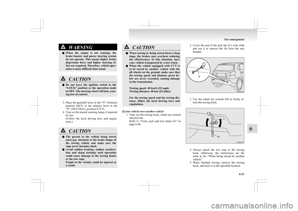
If your vehicle tows another vehicle 1. Take
out the towing hook, wheel nut wrench
and jack bar.
Refer to “Tools, jack and tyre repair kit” on
page 6-06. 2. Cover
the end of the jack bar (C) with cloth
and use it to remove the lid from the rear
bumper. 3. Use
the wheel nut wrench (D) to firmly at-
tach the towing hook. 4. Always
attach the tow rope to the towing
hook. Otherwise, the instructions are the
same as for “When being towed by another
vehicle”.
5. When finished towing, remove the towing hook, and stow it in the specified location. For emergencies
6-21 6