Page 310 of 368

NOTE
l If
this does not close the bonnet, release it
from a slightly higher position.
l Do not press down the bonnet hard with a
hand as it may damage the bonnet.
l For vehicles equipped with the security
alarm system with the interior alarm sensor,
if you drive with the bonnet left open, warn-
ing display is displayed on the information
screen in the multi-information display.
Type 1 Type 2 Engine oil
E01000402413
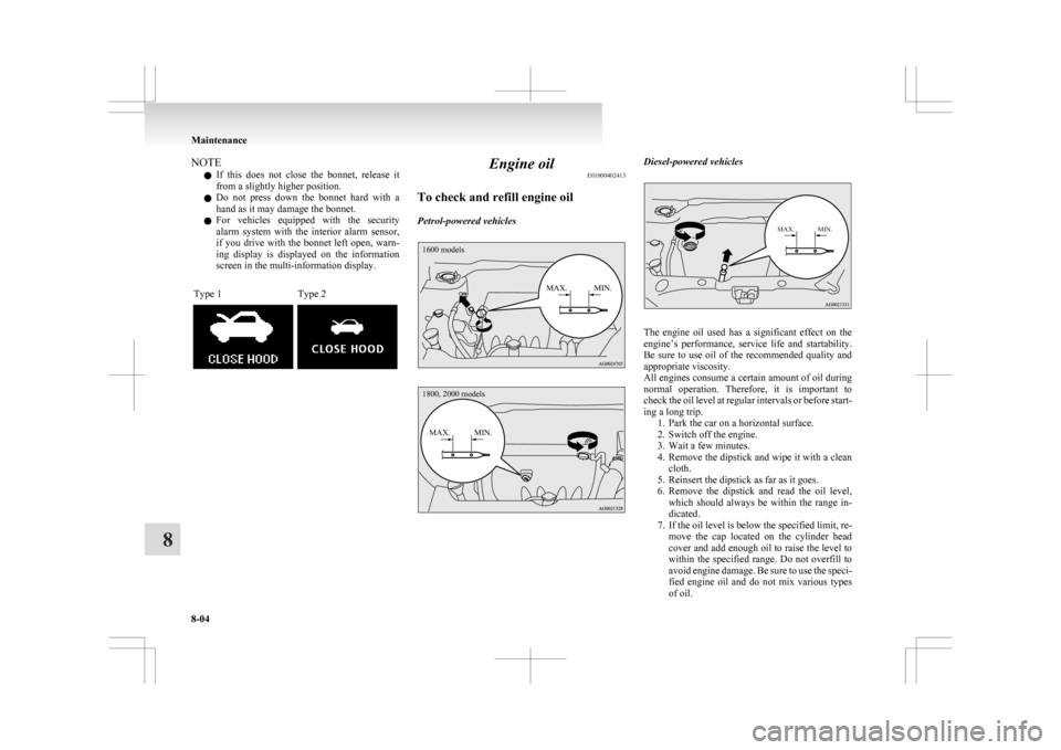
To check and refill engine oil
Petrol-powered vehicles
1600 models
MAX. MIN.
1800, 2000 models
MAX. MIN. Diesel-powered vehicles
MAX. MIN.
The engine oil used has a significant effect on the
engine’s
performance, service life and startability.
Be sure to use oil of the recommended quality and
appropriate viscosity.
All engines consume a certain amount of oil during
normal operation. Therefore, it is important to
check the oil level at regular intervals or before start-
ing a long trip. 1. Park the car on a horizontal surface.
2. Switch off the engine.
3. Wait a few minutes.
4. Remove the dipstick and wipe it with a cleancloth.
5. Reinsert the dipstick as far as it goes.
6. Remove the dipstick and read the oil level, which should always be within the range in-
dicated.
7. If the oil level is below the specified limit, re- move the cap located on the cylinder head
cover and add enough oil to raise the level to
within the specified range. Do not overfill to
avoid engine damage. Be sure to use the speci-
fied engine oil and do not mix various types
of oil. Maintenance
8-04
8
Page 319 of 368

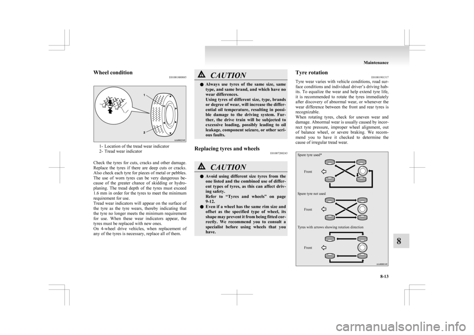
Wheel condition
E010018008851- Location of the tread wear indicator
2-
Tread wear indicator
Check the tyres for cuts, cracks and other damage.
Replace the tyres if there are deep cuts or cracks.
Also check each tyre for pieces of metal or pebbles.
The use of worn tyres can be very dangerous be-
cause of the greater chance of skidding or hydro-
planing. The tread depth of the tyres must exceed
1.6 mm in order for the tyres to meet the minimum
requirement for use.
Tread wear indicators will appear on the surface of
the tyre as the tyre wears, thereby indicating that
the tyre no longer meets the minimum requirement
for use. When these wear indicators appear, the
tyres must be replaced with new ones.
On 4-wheel drive vehicles, when replacement of
any of the tyres is necessary, replace all of them. CAUTION
l
Always
use tyres of the same size, same
type, and same brand, and which have no
wear differences.
Using tyres of different size, type, brands
or degree of wear, will increase the differ-
ential oil temperature, resulting in possi-
ble damage to the driving system. Fur-
ther, the drive train will be subjected to
excessive loading, possibly leading to oil
leakage, component seizure, or other seri-
ous faults.
Replacing tyres and wheels E01007200243 CAUTION
l
Avoid
using different size tyres from the
one listed and the combined use of differ-
ent types of tyres, as this can affect driv-
ing safety.
Refer to “Tyres and wheels” on page
9-12.
l Even if a wheel has the same rim size and
offset as the specified type of wheel, its
shape may prevent it from being fitted cor-
rectly. We recommend you to consult a
specialist before using wheels that you
have. Tyre rotation
E01001901317
Tyre
wear varies with vehicle conditions, road sur-
face conditions and individual driver’s driving hab-
its. To equalize the wear and help extend tyre life,
it is recommended to rotate the tyres immediately
after discovery of abnormal wear, or whenever the
wear difference between the front and rear tyres is
recognizable.
When rotating tyres, check for uneven wear and
damage. Abnormal wear is usually caused by incor-
rect tyre pressure, improper wheel alignment, out
of balance wheel, or severe braking. We recom-
mend you to have it checked to determine the
cause of irregular tread wear.
Front Front Front
Spare tyre used*
Spare tyre not used
Tyres with arrows showing rotation direction Maintenance
8-13 8
Page 328 of 368

No. Symbol Electrical system Capaci-
ties
17 Head-
lamp low
beam
(right) Dis-
charge 20 A
18 Head-
lamp low
beam (left) Halogen 10 A
19 Head-
lamp low
beam
(right) Halogen 10 A
20 ENG/POWER 10 A
21 Ignition coil 10 A
22 ENG/POWER 20 A
Fuel line heater 25 A
23 Fuel pump 15 A
24 Starter 30 A*
25 — ——
26 Anti-lock brake
system 40 A*
27 Anti-lock brake
system 30 A* No. Symbol Electrical system Capaci-
ties
28 Air conditioning
condenser fan mo- tor 30 A*
29 Radiator fan motor 40 A*
30 IOD IOD 30 A
31 Audio system amp 30 A
32 Diesel 30 A
33 — Spare fuse 10 A
34 — Spare fuse 15 A
35 — Spare fuse 20 A *: Fusible link
l Some
fuses may not be installed on your ve-
hicle, depending on the vehicle model or spec-
ifications.
l The table above shows the main equipment
corresponding to each fuse.
The fuse box does not contain spare 7.5 A, 25 A or
30 A fuses. If one of these fuses burns out, substi-
tute with the following fuse.
7.5 A: 10 A spare fuse
25 A: 20 A spare fuse
30 A: 30 A audio system amp fuse
When using a substitute fuse, replace with a fuse of
the correct capacity as soon as possible. Identification of fuse Capacity Colour
7.5 A Brown
10 A Red
15 A Blue
20 A Yellow
25 A Natural (White)
30 A Green (fuse type)/
Pink (fusible link type)
40 A Green (fusible link type) Fuse replacement
E01007800630
1. Before replacing a fuse, always turn off the
electrical circuit concerned and turn the igni-
tion switch to the “LOCK” position or put
the operation mode in OFF.
2. Remove the fuse puller (A) from the inside of the fuse box in the engine compartment. 3. Referring
to the fuse load capacity table,
check the fuse pertaining to the problem. Maintenance
8-22
8
Page 336 of 368
CAUTION
l
Handle halogen lamp bulbs with care.
The gas inside halogen lamp bulbs is high-
ly pressurized, so dropping, knocking, or
scratching a halogen lamp bulb can cause
it to shatter.
l Never hold the halogen lamp bulb with a
bare hand, dirty glove, etc.
The oil from your hand could cause the
bulb to break the next time the fog lamps
are operated.
If the glass surface is dirty, it must be
cleaned with alcohol, paint thinner, etc.,
and refit it after drying it thoroughly. Daytime running lamps*
E01011200055
1. Pull
the lamp cover (A) to the direction of
the arrow to remove it. 2. Remove
the screws (B), and then remove the
lamp unit. 3. Turn the bulb (C) anticlockwise to remove it.
Type 1
Type 2 4. While
holding down the tab (D), pull out the
socket (E). 5. To
install the bulb, perform the removal
steps in reverse. Maintenance
8-30
8