2009 MITSUBISHI ASX glove box
[x] Cancel search: glove boxPage 265 of 368
USB input terminal*
E00761900015
You
can connect your USB memory device or
iPod* to play music files stored in the USB memo-
ry device or iPod.
The following explains how to connect and remove
a USB memory device or iPod.
Refer to the following sections for details on how
to play music files:
Refer to “To play from a USB memory device” on
page 5-27.
*: “iPod” is a registered trademark of Apple Inc. in
the United States and other countries.
How to connect a USB memory device E00762000084
1. Park
your vehicle in a safe place and turn the
ignition switch to the “LOCK” position or
put the operation mode in OFF.
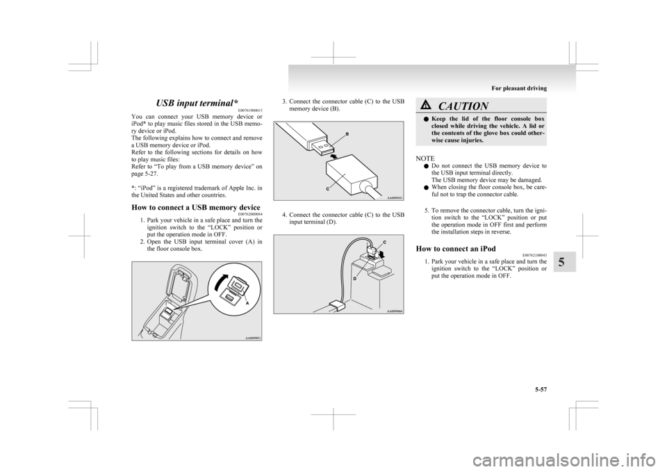
2. Open the USB input terminal cover (A) in the floor console box. 3. Connect
the connector cable (C) to the USB
memory device (B). 4. Connect
the connector cable (C) to the USB
input terminal (D). CAUTION
l
Keep
the lid of the floor console box
closed while driving the vehicle. A lid or
the contents of the glove box could other-
wise cause injuries.
NOTE l Do
not connect the USB memory device to
the USB input terminal directly.
The USB memory device may be damaged.
l When closing the floor console box, be care-
ful not to trap the connector cable.
5. To remove the connector cable, turn the igni- tion switch to the “LOCK” position or put
the operation mode in OFF first and perform
the installation steps in reverse.
How to connect an iPod E00762100043
1. Park
your vehicle in a safe place and turn the
ignition switch to the “LOCK” position or
put the operation mode in OFF. For pleasant driving
5-57 5
Page 273 of 368
NOTE
l The
interior lamp auto cut-out function can
be deactivated. The time until the lamps auto-
matically go off can be adjusted. For details
and support, consult your nearest
MITSUBISHI MOTORS Authorized Service
Point.
On vehicles equipped with MITSUBISHI
Multi-Communication System (MMCS),
screen operations can be used to make the ad-
justment. Refer to the separate owner’s man-
ual for details. Storage spaces
E00713101664 CAUTION
l
Never
leave lighters, cans of carbonated
drink, and spectacles in the cabin when
parking the vehicle in hot sunshine. The
cabin will become extremely hot, so light-
ers and other flammable items may catch
fire and unopened drink cans (including
soft drink or beer cans) may rupture. Al-
so, spectacles with plastic lenses or mate-
rials could deform or crack.
l Keep the lids of storage spaces closed
while driving the vehicle. A lid or the con-
tents of a storage space could otherwise
cause injuries.
NOTE l When
leaving your vehicle, do not leave val-
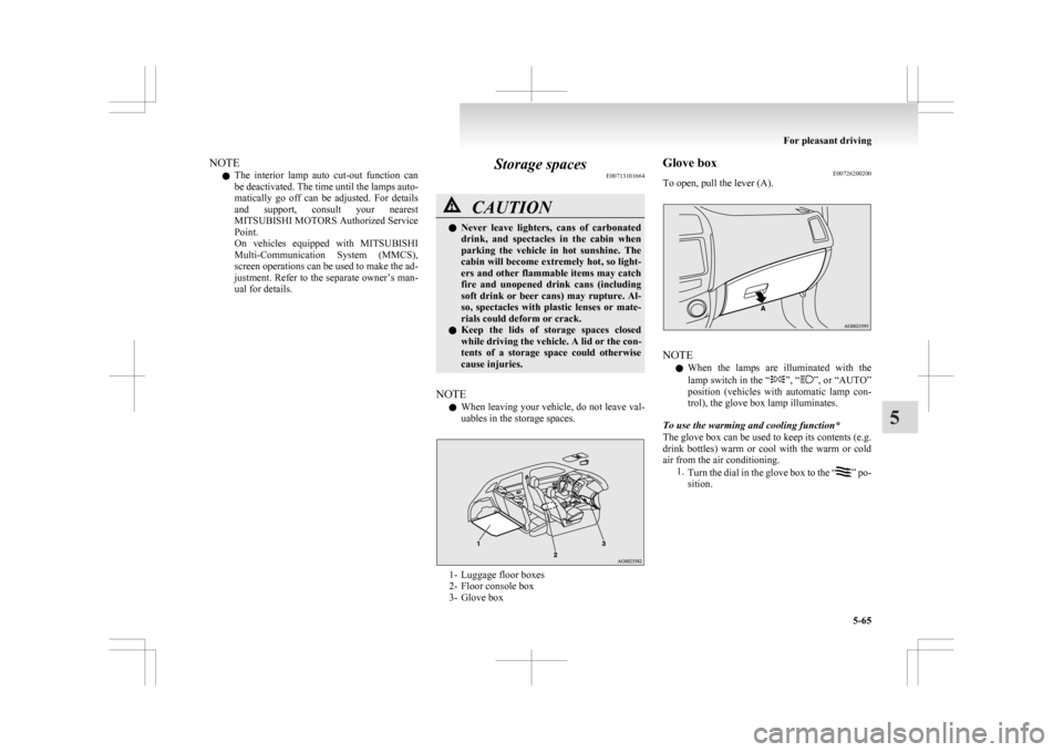
uables in the storage spaces. 1- Luggage floor boxes
2-
Floor console box
3- Glove box Glove box
E00726200200
To open, pull the lever (A). NOTE
l When
the lamps are illuminated with the
lamp switch in the “ ”, “ ”,
or “AUTO”
position (vehicles with automatic lamp con-
trol), the glove box lamp illuminates.
To use the warming and cooling function*
The glove box can be used to keep its contents (e.g.
drink bottles) warm or cool with the warm or cold
air from the air conditioning. 1.Turn the dial in the glove box to the “ ”
po-
sition. For pleasant driving
5-65 5
Page 274 of 368
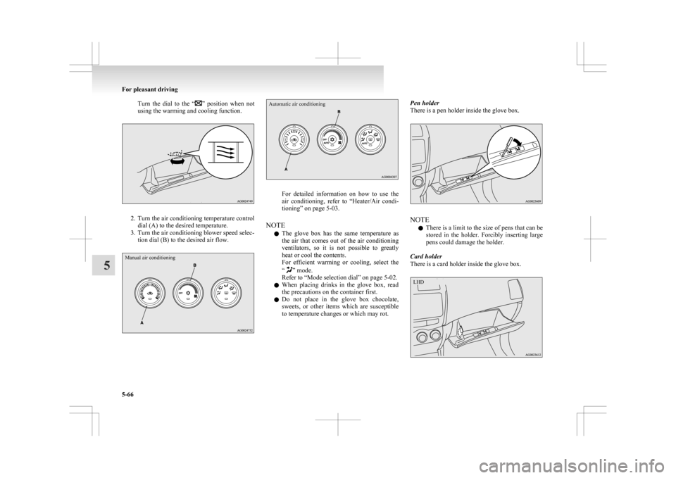
Turn the dial to the “ ” position when not
using the warming and cooling function. 2. Turn
the air conditioning temperature control
dial (A) to the desired temperature.
3. Turn the air conditioning blower speed selec- tion dial (B) to the desired air flow.
Manual air conditioning
Automatic air conditioning For detailed information on how to use the
air
conditioning, refer to “Heater/Air condi-
tioning” on page 5-03.
NOTE l The glove box has the same temperature as
the air that comes out of the air conditioning
ventilators, so it is not possible to greatly
heat or cool the contents.
For efficient warming or cooling, select the
“ ” mode.
Refer to “Mode selection dial” on page
5-02.
l When placing drinks in the glove box, read
the precautions on the container first.
l Do not place in the glove box chocolate,
sweets, or other items which are susceptible
to temperature changes or which may rot. Pen holder
There is a pen holder inside the glove box.
NOTE
l There
is a limit to the size of pens that can be
stored in the holder. Forcibly inserting large
pens could damage the holder.
Card holder
There is a card holder inside the glove box. For pleasant driving
5-66
5 LHD
Page 325 of 368
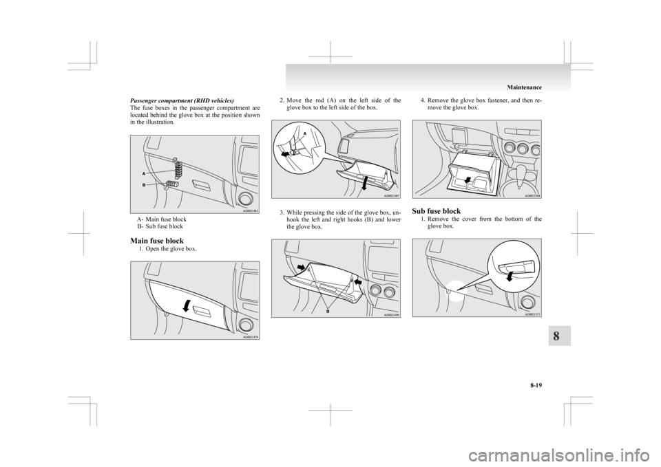
Passenger compartment (RHD vehicles)
The
fuse boxes in the passenger compartment are
located behind the glove box at the position shown
in the illustration. A- Main fuse block
B-
Sub fuse block
Main fuse block 1. Open the glove box. 2. Move
the rod (A) on the left side of the
glove box to the left side of the box. 3. While
pressing the side of the glove box, un-
hook the left and right hooks (B) and lower
the glove box. 4. Remove
the glove box fastener, and then re-
move the glove box. Sub fuse block
1. Remove
the cover from the bottom of the
glove box. Maintenance
8-19 8
Page 326 of 368
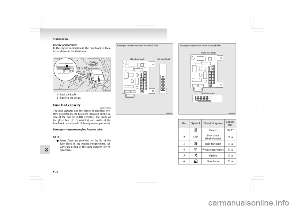
Engine compartment
In
the engine compartment, the fuse block is loca-
ted as shown in the illustration. 1- Push the knob.
2-
Remove the cover.
Fuse load capacity E01007700482
The fuse capacity and the names of electrical sys-
tems
protected by the fuses are indicated on the in-
side of the fuse lid (LHD vehicles), the inside of
the glove box (RHD vehicles) and inside of the
fuse block cover (inside of the engine compartment).
Passenger compartment fuse location table
NOTE
l Spare fuses are provided on the lid of the
fuse block in the engine compartment. Al-
ways use a fuse of the same capacity for re-
placement.
Passenger compartment fuse location (LHD)
Main fuse block Sub fuse blockPassenger compartment fuse location (RHD)
Sub fuse block Main fuse block No. Symbol Electrical system Capaci-
ties
1 Heater 30 A*
2 Stop lamps
(Brake lamps) 15 A
3 Rear fog lamp 10 A
4 Windscreen wipers 30 A
5 Option 10 A
6 Door locks 20 AMaintenance
8-20
8
Page 330 of 368

Outside
E01003302527Front1- Front turn-signal lamps: 21 W (WY21W)
2-
Headlamps, high-beam: 60 W (HB3)
3- Type 1 Front fog lamps: 35 W (H8)
Daytime running lamps: 13 W (P13W)
Type 2 Daytime running lamps: 13 W (P13W)
Type 3 Front fog lamps: 55 W (H11)
4- Headlamps, low beam Halogen: 55 W (H11)
High intensity discharge *2
: 35 W
5- Position lamps: 5 W (W5W)
6- Side turn-signal lamps (on fender) *1
,*2
: 5 W
7- Side turn-signal lamps (on outside rear-view
mirror) *1
*1 : if so equipped
*2 : Have the lamps bulbs replaced at a
MITSUBISHI MOTORS
Authorized
Service Point.
Codes in parentheses indicate bulb types. WARNING
l Always
consult a specialist when repair-
ing or replacing the bulbs of high intensi-
ty discharge headlamps.
This is because the power circuit, bulbs
and electrodes generate a high voltage
that could cause an electric shock.
NOTE l An
LED, not a bulb, is used in the side turn-
signal lamp (on outside rear-view mirror).
Contact a MITSUBISHI MOTORS Author-
ized Service Point when there is a need for re-
pair or replacement.
l For the side turn-signal lamp (on fender), it
is not possible to repair or replace just the bulb.
Contact a MITSUBISHI MOTORS Author-
ized Service Point when there is a need for re-
pair or replacement.
Rear 8- High-mounted stop lamp
9-
Licence plate lamps: 5 W (W5W)
10- Rear fog lamp: 21 W (W21W)
11- Reversing lamps: 16 W (W16W) 12- Rear turn-signal lamps: 21 W (W21W)
13-
Stop and tail lamps
Codes in parentheses indicate bulb types.
NOTE l An LED, not a bulb, is used in the stop lamp/
tail lamp and high-mounted stop lamp. Con-
tact a MITSUBISHI MOTORS Authorized
Service Point when there is a need for repair
or replacement.
Inside E01003401749 1- Room lamp (rear)*: 8 W
2-
Vanity mirror lamps*: 3 W
3- Room lamp (front) & map lamps: 8 W
4- Luggage room lamp: 5 W
5- Glove box lamp: 1.4 W
*: if so equipped Maintenance
8-24
8
Page 332 of 368

6. While holding down the tab (F), pull out the
socket (G). 7. To
install the bulb, perform the removal
steps in reverse. CAUTION
l
Handle
halogen lamp bulbs with care.
The gas inside halogen lamp bulbs is high-
ly pressurized, so dropping, knocking, or
scratching a halogen lamp bulb can cause
it to shatter.
l Never hold the halogen lamp bulb with a
bare hand, dirty glove, etc.
The oil from your hand could cause the
bulb to break the next time the head-
lamps are operated.
If the glass surface is dirty, it must be
cleaned with alcohol, paint thinner, etc.,
and refit it after drying it thoroughly. Headlamps (low beam, for vehicles
with high intensity discharge head-
lamps)
E01010100132
Do not attempt to disassemble or repair headlamps,
and do not attempt to replace their bulbs. WARNING
l A high voltage is present in the power cir-
cuit
and in the bulbs and bulb terminals.
To avoid the risk of an electric shock, con-
tact a MITSUBISHI MOTORS Author-
ized Service Point whenever repair or re-
placement is necessary. Headlamps (High-beam)
E01009400135
1. When
replacing the bulb on the left side of
the vehicle in the case of diesel-powered ve-
hicles, remove the bolt (A) holding down the
relay box and move the relay box towards
the rear of the vehicle. *: Front of the vehicle
2.
Turn the cap (B) anticlockwise to remove it. *: Front of the vehicleMaintenance
8-26
8
Page 333 of 368

3. Turn the bulb (C) anticlockwise to remove it.
*: Front of the vehicle
4. While holding down the tab (D), pull out the
socket (E). 5. To
install the bulb, perform the removal
steps in reverse. CAUTION
l
Handle
halogen lamp bulbs with care.
The gas inside halogen lamp bulbs is high-
ly pressurized, so dropping, knocking, or
scratching a halogen lamp bulb can cause
it to shatter.
l Never hold the halogen lamp bulb with a
bare hand, dirty glove, etc.
The oil from your hand could cause the
bulb to break the next time the head-
lamps are operated.
If the glass surface is dirty, it must be
cleaned with alcohol, paint thinner, etc.,
and refit it after drying it thoroughly. Position lamps
E01003700947
1. When
replacing the bulb on the left side of
the vehicle in the case of diesel-powered ve-
hicles, remove the bolt (A) holding down the
relay box and move the relay box towards
the rear of the vehicle. *: Front of the vehicle
2. When
replacing the bulb on the right side of
the vehicle in the case of diesel-powered ve-
hicles, remove the bolts (B) holding down
the reservoir tank and move the reservoir tank. *: Front of the vehicle Maintenance
8-27 8