2009 MINI COOPER CONVERTIBLE turn signal
[x] Cancel search: turn signalPage 62 of 172
Everything under control
60
6.Wait for the display to change to month.
7.Set the month and year in the same way.
8.Wait for the display to change.
The settings are stored.
Check Control
The concept
The Check Control monitors vehicle functions
and alerts you to any malfunctions in the sys-
tems monitored. Check Control messages
involve indicator or warning lamps in the dis-
plays and, in some circumstances, an acoustic
signal. To adjust the volume of the signal, refer
to the Owner's Manual for Radio.
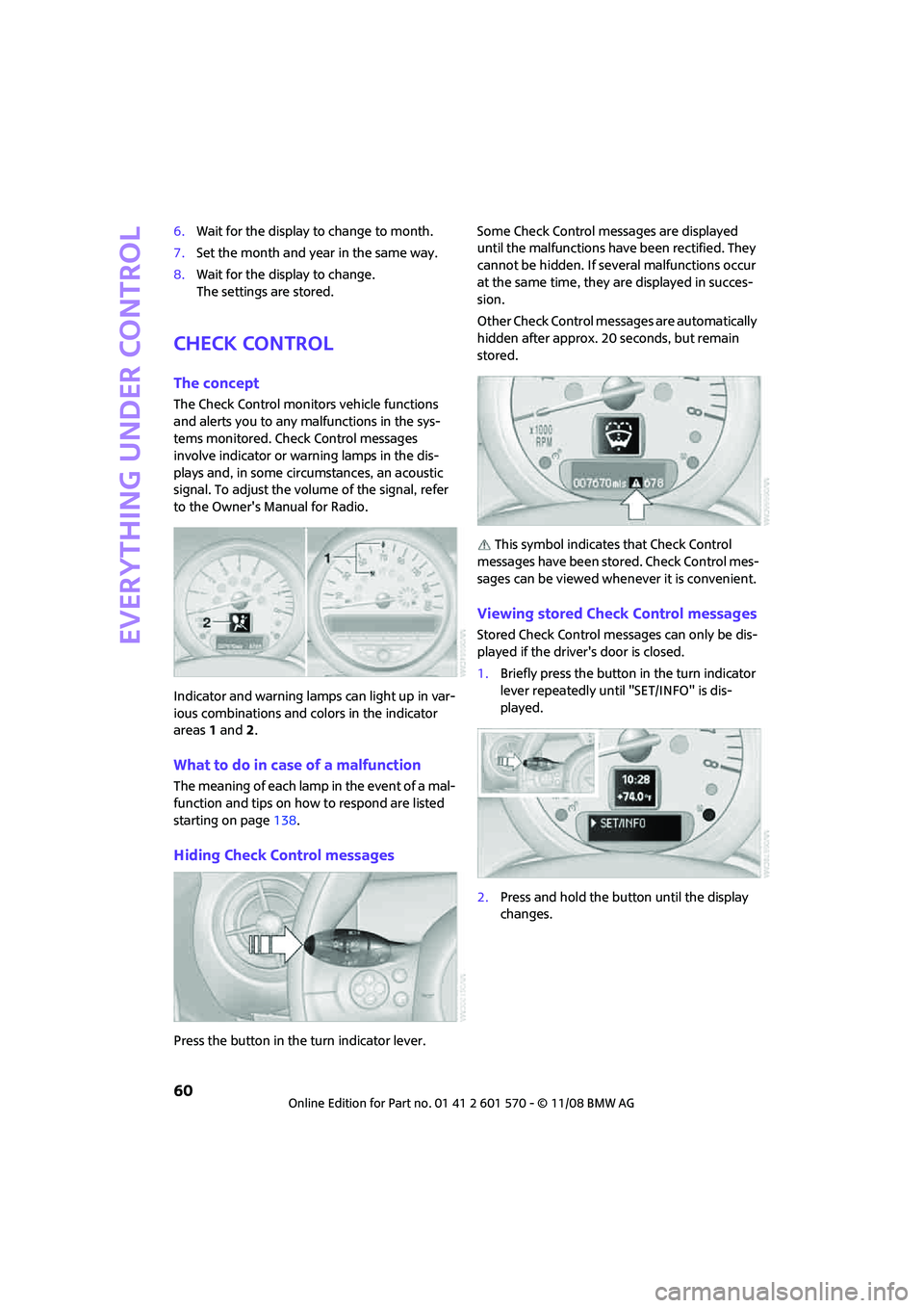
Indicator and warning lamps can light up in var-
ious combinations and colors in the indicator
areas 1 and2.
What to do in case of a malfunction
The meaning of each lamp in the event of a mal-
function and tips on how to respond are listed
starting on page138.
Hiding Check Control messages
Press the button in the turn indicator lever.Some Check Control messages are displayed
until the malfunctions have been rectified. They
cannot be hidden. If several malfunctions occur
at the same time, they are displayed in succes-
sion.
Other Check Control messages are automatically
hidden after approx. 20 seconds, but remain
stored.
This symbol indicates that Check Control
messages have been stored. Check Control mes-
sages can be viewed whenever it is convenient.
Viewing stored Check Control messages
Stored Check Control messages can only be dis-
played if the driver's door is closed.
1.Briefly press the button in the turn indicator
lever repeatedly until "SET/INFO" is dis-
played.
2.Press and hold the button until the display
changes.
Page 69 of 172
REFERENCEAT A GLANCE CONTROLS DRIVING TIPS MOBILITY
67
Functional requirement
In order to assure the reliable reporting of a flat
tire, the system must be reset while all tire infla-
tion pressures are correct.
Always use wheels with TPM electronics. Other-
wise, the system may malfunction.
Each time a tire inflation pressure has
been corrected or a wheel or tire has been
changed, reset the system.<
System limitations
TPM cannot warn you in advance of sud-
den severe tire damage caused by outside
influences.<
The system does not work correctly if it has not
been reset; for example, a flat tire may be indi-
cated even though the tire inflation pressures
are correct.
The system is inactive and cannot indicate a flat
tire if a wheel without TPM electronics, such as a
compact spare wheel
*, has been mounted, or if
TPM is temporarily malfunctioning due to other
systems or devices using the same radio fre-
quency.
Resetting the system
Each time a tire inflation pressure has
been corrected or a wheel or tire has been
changed, reset the system.<
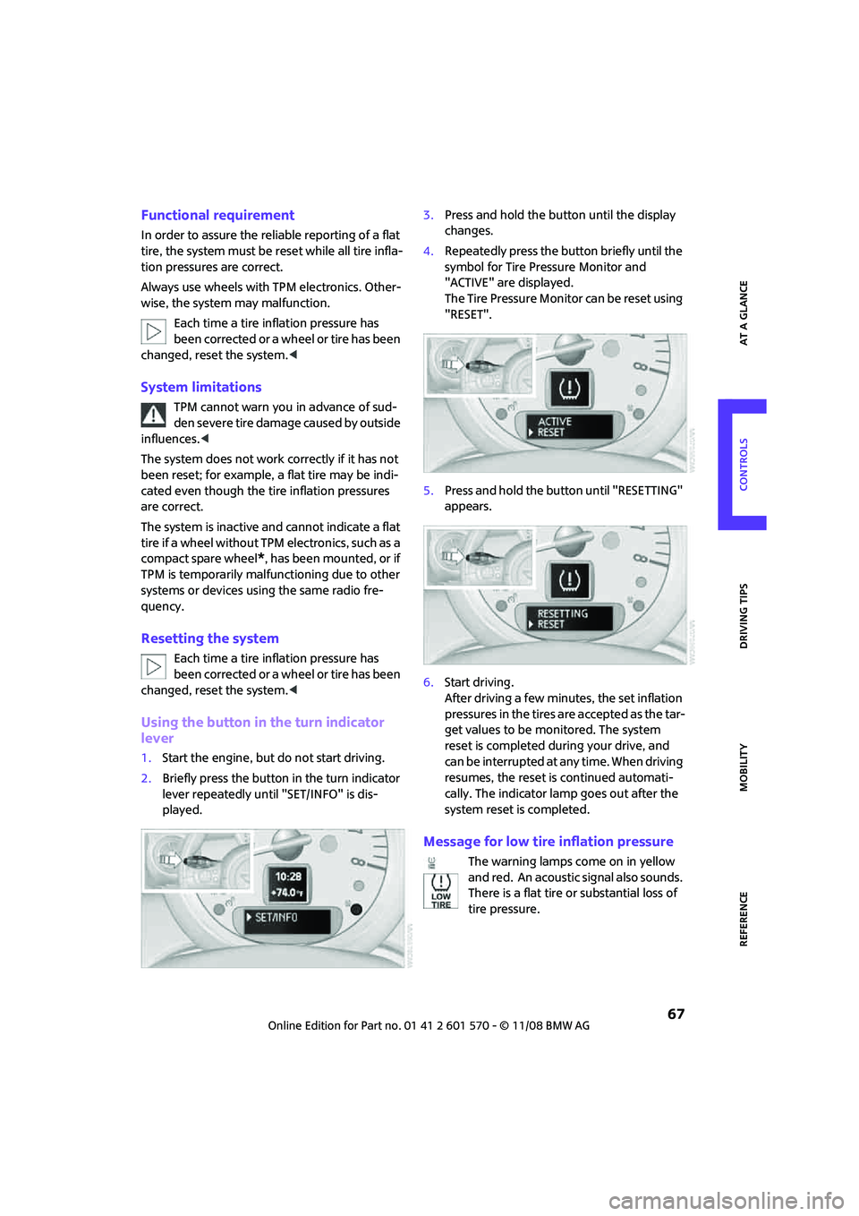
Using the button in the turn indicator
lever
1.Start the engine, but do not start driving.
2.Briefly press the button in the turn indicator
lever repeatedly until "SET/INFO" is dis-
played.3.Press and hold the button until the display
changes.
4.Repeatedly press the button briefly until the
symbol for Tire Pressure Monitor and
"ACTIVE" are displayed.
The Tire Pressure Monitor can be reset using
"RESET".
5.Press and hold the button until "RESETTING"
appears.
6.Start driving.
After driving a few minutes, the set inflation
pressures in the tires are accepted as the tar-
get values to be monitored. The system
reset is completed during your drive, and
can be interrupted at any time. When driving
resumes, the reset is continued automati-
cally. The indicator lamp goes out after the
system reset is completed.
Message for low tire inflation pressure
The warning lamps come on in yellow
and red. An acoustic signal also sounds.
There is a flat tire or substantial loss of
tire pressure.
Page 77 of 172

REFERENCEAT A GLANCE CONTROLS DRIVING TIPS MOBILITY
75
4.Briefly press the button repeatedly until the
symbol and "SET" are displayed.
5.Press and hold the button until the display
changes.
6.Briefly press the button repeatedly until the
display shows the illustrated symbol, arrow.
7.Press and hold the button until the display
changes.
8.Briefly press the button to select:
>
Daytime running lamps activated.
>
Daytime running lamps deactivated.
9.Press the button for a longer period.
The setting is stored.High beams/roadside
parking lamps
1Turn signal indicators/roadside parking
lamps
*
2Switching on high beams
3Switching off high beams/headlamp flasher
Roadside parking lamps, left or right*
The vehicle can be illuminated on one side for
parking. Comply with local regulations when
doing so.
Switching on
After parking the vehicle, press the lever up or
down, arrow 1.
The roadside parking lamps drain the bat-
tery. Therefore, do not leave them on for
unduly long periods of time, otherwise the bat-
tery might not have enough power to start the
engine.<
Switching off
Press the lever up or down to the pressure point.
Page 127 of 172
REFERENCEAT A GLANCE CONTROLS DRIVING TIPS MOBILITY
125
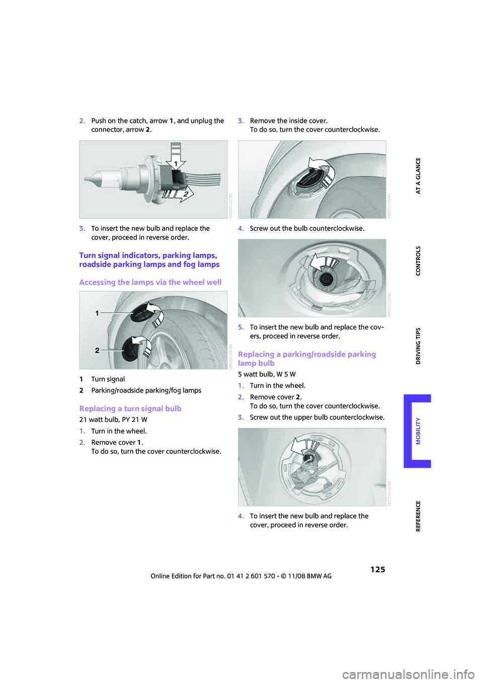
2.Push on the catch, arrow 1, and unplug the
connector, arrow2.
3.To insert the new bulb and replace the
cover, proceed in reverse order.
Turn signal indicators, parking lamps,
roadside parking lamps and fog lamps
Accessing the lamps via the wheel well
1Turn signal
2Parking/roadside parking/fog lamps
Replacing a turn signal bulb
21 watt bulb, PY 21 W
1.Turn in the wheel.
2.Remove cover 1.
To do so, turn the cover counterclockwise.3.Remove the inside cover.
To do so, turn the cover counterclockwise.
4.Screw out the bulb counterclockwise.
5.To insert the new bulb and replace the cov-
ers, proceed in reverse order.
Replacing a parking/roadside parking
lamp bulb
5 watt bulb, W 5 W
1.Turn in the wheel.
2.Remove cover 2.
To do so, turn the cover counterclockwise.
3.Screw out the upper bulb counterclockwise.
4.To insert the new bulb and replace the
cover, proceed in reverse order.
Page 128 of 172
Replacing components
126
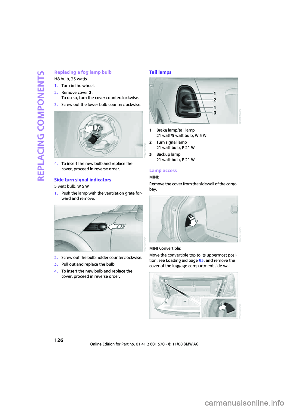
Replacing a fog lamp bulb
H8 bulb, 35 watts
1.Turn in the wheel.
2.Remove cover 2.
To do so, turn the cover counterclockwise.
3.Screw out the lower bulb counterclockwise.
4.To insert the new bulb and replace the
cover, proceed in reverse order.
Side turn signal indicators
5 watt bulb, W 5 W
1.Push the lamp with the ventilation grate for-
ward and remove.
2.Screw out the bulb holder counterclockwise.
3.Pull out and replace the bulb.
4.To insert the new bulb and replace the
cover, proceed in reverse order.
Tail lamps
1Brake lamp/tail lamp
21 watt/5 watt bulb, W 5 W
2Turn signal lamp
21 watt bulb, P 21 W
3Backup lamp
21 watt bulb, P 21 W
Lamp access
MINI:
Remove the cover from the sidewall of the cargo
bay.
MINI Convertible:
Move the convertible top to its uppermost posi-
tion, see Loading aid page93, and remove the
cover of the luggage compartment side wall.
Page 138 of 172

Giving and receiving assistance
136
Access to screw thread
Push out the cover of the towing eye out of the
recess in the bumper.
Front
Rear
Being towed
Make sure that the ignition is switched on,
refer to page43, otherwise the low
beams, tail lamps, turn signal indicators and
windshield wipers may be unavailable. Do not
tow the vehicle with just the rear axle raised, as
this would allow the steering to turn. <
There is no power assist while the engine is off.
Thus, braking and steering will require increased
effort.
Switch on the hazard warning flashers, depend-
ing on local regulations.
Manual transmission
Gearshift lever in neutral position.
Automatic transmission
Tow vehicles with automatic transmission
only with a tow truck or with the front
wheels lifted; otherwise the transmission can be
damaged.<
Towing with a tow bar
The towing vehicle must not be lighter
than the towed vehicle, otherwise it may
be impossible to maintain control.<
The tow fittings used should be on the same side
on both vehicles. Should it prove impossible to
avoid mounting the tow bar at an angle, please
observe the following:
>Clearance and maneuvering capability will
be sharply limited during cornering.
>The tow bar will generate lateral forces if it is
attached offset.
Attach the tow bar to the tow fittings only,
as attaching it to other parts of the vehicle
could result in damage.<
Towing with a tow rope
When starting off in the towing vehicle, make
sure that the tow rope is taut.
To avoid jerking and the associated
stresses on vehicle components when
towing, always use nylon ropes or nylon straps.
Attach the tow rope to the tow fittings only, as
attaching it to other parts of the vehicle could
result in damage.<
Towing with a tow truck
Have the MINI or MINI Convertible transported
by a tow truck with a so-called lift sling or on a
flatbed.
Do not lift the vehicle by a tow fitting or
body and chassis parts, otherwise damage
may result.<
Page 140 of 172
Indicator and warning lamps
138
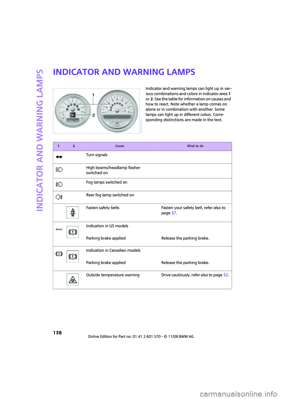
Indicator and warning lamps
Indicator and warning lamps can light up in var-
ious combinations and colors in indicator area 1
or2. See the table for information on causes and
how to react. Note whether a lamp comes on
alone or in combination with another. Some
lamps can light up in different colors. Corre-
sponding distinctions are made in the text.
12Cause What to do
Turn signals
High beams/headlamp flasher
switched on
Fog lamps switched on
Rear fog lamp switched on
Fasten safety belts Fasten your safety belt, refer also to
page37.
Indication in US models
Parking brake applied Release the parking brake.
Indication in Canadian models
Parking brake applied Release the parking brake.
Outside temperature warning Drive cautiously, refer also to page52.
Page 162 of 172

From A to Z
160
Consumption, refer to Average
fuel consumption53
Control Display
– settings55
Controls and displays10
Convenience operation
– convertible top22
Convenience start, refer to
Starting the engine44
Convenient access26
– replacing the battery27
Convenient operation
– windows20
Convertible top29
Coolant115
– checking level115
– filling115
Coolant temperature52
Cooling fluid, refer to
Coolant115
Cooling, maximum81
Copyright2
Cruising range53
Cup holders87
Curb weight, refer to
Weights155
Current fuel consumption54
D
Dashboard instruments, refer
to Displays12
Dashboard lighting, refer to
Instrument lighting76
Dashboard, refer to Cockpit10
Data152
– capacities156
– dimensions153
– engine152
– weights155
Date
– setting59
Daytime running lamps74
DBC Dynamic Brake Control,
refer to Brake assist63
Deactivating front passenger
airbags71
Deadlocking, refer to
Locking20Defect
– door lock22
– fuel filler door100
Defogging windows80,82
Defrost position, refer to
Defrosting windows80,82
Defrosting windows80,82
Defrosting windows and
removing condensation
– air conditioner80
– automatic climate control82
Differential, breaking in90
Digital clock52
Dimensions153
Dipstick, engine oil114
Directional indicators, refer to
Turn signals47
Displacement, refer to Engine
data152
Display lighting, refer to
Instrument lighting76
Displays12
– instrument combination12
Displays and controls10
Displays, care122
Disposal
– of coolant115
– remote control battery27
– vehicle battery132
Distance remaining to service,
refer to Service
requirements57
Distance warning, refer to Park
Distance Control PDC62
Diving stability control
systems62
Door key, refer to Integrated
key/remote control18
Door lock22
Door lock, confirmation
signals20
Doors, manual operation22
DOT Quality Grades109
Drinks holders, refer to Cup
holders87
Drive-off assistant, refer to Hill
Start Assist64
Driving dynamics control, refer
to Sport button64Driving lamps, refer to Parking
lamps/low beams73
Driving notes90
Driving off on inclines, refer to
Hill Start Assist64
Driving through water91
Driving tips, refer to Driving
notes90
Dry air, refer to Cooling
function82
DTC Dynamic Traction Control
DTC63
Dynamic Brake Control DBC,
refer to Brake assist63
Dynamic Stability Control
DSC63
Dynamic Traction Control63
E
Electric power windows
– initializing29
Electrical malfunction
– convertible top32
– door lock22
– fuel filler door100
– trunk lid24
Electronic brake-force
distribution63
Electronic Stability Program
ESP, refer to Dynamic
Stability Control DSC63
Emergency operation, refer to
Manual operation
– convertible top32
– door lock22
– fuel filler door100
– transmission lock, automatic
transmission47
– trunk lid24
Emergency services, refer to
Roadside Assistance134