Page 129 of 176

REFERENCEAT A GLANCE CONTROLS DRIVING TIPS MOBILITY
127
sumer in question, otherwise short circuits could
result. To avoid possible injury or equipment
damage when replacing bulbs, observe any
instructions provided by the bulb manufac-
turer.<
Caring for headlamps, refer to page123.
For any bulb replacement not described
below, contact a MINI Dealer or a work-
shop that has specially trained personnel work-
ing in accordance with the specifications of the
MINI manufacturer.<
For checking and adjusting headlamp aim,
please contact your MINI Dealer.<
Light-emitting diodes LEDs
Light-emitting diodes installed behind translu-
cent lenses serve as the light sources for many of
the controls and displays in your vehicle. These
light-emitting diodes are related to conven-
tional laser diodes, and legislation defines them
as Class 1 light-emitting diodes.
Do not remove the covers or expose the
eyes directly to the unfiltered light source
for several hours, otherwise this could cause irri-
tation to the retina.<
Bi-Xenon lamps*
The service life of these bulbs is very long and
the probability of failure very low, provided that
they are not switched on and off an excessive
number of times. If a xenon lamp fails neverthe-
less, switch on the fog lamps and continue the
journey with great care, provided that local leg-
islation does not prohibit this.
Have any work on the xenon lamp system,
including bulb replacement, carried out
only by a MINI Dealer or a workshop that has
specially trained personnel working in accor-
dance with the specifications of the MINI manu-
facturer. Due to high voltage, there is a risk of
fatal injury if work on the xenon lamps is carried
out improperly.<
Halogen low beams and high beams
H13 bulb, 60/55 wattsThe H13 bulb is pressurized. Therefore,
wear safety glasses and protective gloves.
Otherwise there is a risk of injury if the bulb is
damaged.<
Be careful when installing the cover,
otherwise leaks could occur and cause
damage to the headlamp system.<
Accessing the lamp from the
engine compartment
The low-beam/high-beam bulb can be changed
from the engine compartment.
Removing the cover:
1.Press the tab.
2.Flip open the cover and take it out of
the holder.
Follow the same steps in reverse order to
reattach the cover.
Be careful when installing the cover,
otherwise leaks could occur and cause
damage to the headlamp system.<
Replacing the bulb
1.Turn the lamp counterclockwise, arrow1,
and remove it, arrow2.
Page 130 of 176
Replacing components
128
2.Push on the catch, arrow 1, and unplug the
connector, arrow2.
3.To insert the new bulb and replace the
cover, proceed in reverse order.
Turn signal indicators, parking lamps,
roadside parking lamps and fog lamps
Accessing the lamps via the wheel well
1Turn signal
2Parking/roadside parking/fog lamps
Replacing a turn signal bulb
21 watt bulb, PY 21 W
1.Turn in the wheel.
2.Remove cover 1.
To do so, turn the cover counterclockwise.3.Remove the inside cover.
To do so, turn the cover counterclockwise.
4.Screw out the bulb counterclockwise.
5.To insert the new bulb and replace the cov-
ers, proceed in reverse order.
Replacing a parking/roadside parking
lamp bulb
5 watt bulb, W 5 W
1.Turn in the wheel.
2.Remove cover 2.
To do so, turn the cover counterclockwise.
3.Screw out the upper bulb counterclockwise.
4.To insert the new bulb and replace the
cover, proceed in reverse order.
Page 131 of 176
REFERENCEAT A GLANCE CONTROLS DRIVING TIPS MOBILITY
129
Replacing a fog lamp bulb
H8 bulb, 35 watts
1.Turn in the wheel.
2.Remove cover 2.
To do so, turn the cover counterclockwise.
3.Screw out the lower bulb counterclockwise.
4.To insert the new bulb and replace the
cover, proceed in reverse order.
Side turn signal indicators
5 watt bulb, W 5 W
1.Push the lamp with the ventilation grate for-
ward and remove.
2.Screw out the bulb holder counterclockwise.
3.Pull out and replace the bulb.
4.To insert the new bulb and replace the
cover, proceed in reverse order.
Tail lamps
1Brake lamp/tail lamp
21 watt/5 watt bulb, W 5 W
2Turn signal lamp
21 watt bulb, P 21 W
3Backup lamp
21 watt bulb, P 21 W
Lamp access
MINI:
Remove the cover from the sidewall of the
cargo bay.
MINI Convertible:
Move the convertible top to its uppermost posi-
tion, see Loading aid page95, and remove the
cover of the luggage compartment side wall.
Page 132 of 176

Replacing components
130
Changing
1.Screw out the desired bulb counterclock-
wise, arrows1.
Additional bulbs are located behind the
sidewall of the cargo bay, arrow 2.
2.To insert the new bulb and replace the
cover, proceed in reverse order.
Rear fog lamp*
21 watt bulb, P 21 W
Access to the lamp via the back or underside of
the bumper.
The illustration shows the fog lamp in the
bumper of the MINI Cooper.
1.Screw out the bulb holder counterclockwise.
2.Screw out and replace the bulb.
3.To insert the new bulb and bulb holder, pro-
ceed in reverse order.
License plate lamps
5 watt bulb, C 5 W1.Using a screwdriver, push the lamp to the
left in the tab of the lamp housing, arrow1.
2.Remove the lamp, arrow 2.
3.Replace the bulb.
4.Insert the lamp.
Center brake lamp
This lamp uses LED technology for operation. In
the event of a malfunction, contact your MINI
Dealer or a workshop that has specially trained
personnel working in accordance with the spec-
ifications of your MINI manufacturer.
Repairing a flat tire
Safety measures in the event of a break-
down:
Park the vehicle as far as possible from mov-
ing traffic and switch on the hazard warning
flashers.
Turn the steering wheel until the front wheels
are in the straight-ahead position and engage
the steering wheel lock. Engage the parking
brake and shift into 1st or reverse gear or place
the selector lever in position P.
All passengers should be outside the vehicle and
in a safe place, e.g. behind a guardrail.
Erect a warning triangle or warning flasher at the
appropriate distance if necessary. Comply with
all safety guidelines and regulations.<
In the event of a flat tire, different procedures
should be followed depending on the equip-
ment included in your vehicle:
>MINI Mobility System, refer to the following
section
>Run-Flat Tires, page114
Page 133 of 176

REFERENCEAT A GLANCE CONTROLS DRIVING TIPS MOBILITY
131
>Tire change with space-saver spare tire,
page133
MINI Mobility System with onboard tool
kit and tire change set*
Follow the instructions on using the Mobil-
ity System found on the compressor and
the sealant bottle.<
Do not remove foreign bodies which have pen-
etrated the tire if possible.
Pull the sticker for the speed restriction off and
apply it to the steering wheel.
The Mobility System with onboard tool kit and
tire change set
* is located under the floor mat in
the cargo bay.
1Filling canister
2Hexagon wrench
*
3Vehicle jack*
4Wheel stud wrench
5Flat screwdriver/Phillips screwdriver,
towing eyelet
6Compressor
7Package with filling hose, valve remover,
valve insert and speed restriction label
Use of the Mobility System may be ineffec-
tive if the tire puncture measures approx.
1/8 in/4 mm or more. Contact the nearest MINI
Dealer if the tire cannot be made drivable with
the Mobility System.<
Liquid sealant
1Filling hose
2Filling canister
Filling
1.Shake the filling canister.
2.Screw the filling hose onto the filling
canister.
3.Unscrew the dust cap from the valve of the
defective tire.
4.Screw out the valve core with the valve
remover. The valve remover is located in a
package with the filling hose.
5.Remove the cap from the filling hose.
6.Push the filling hose onto the tire valve.
7.Hold the filling canister with the cap down
and squeeze.
8.Squeeze the entire contents of the canister
into the tire.
9.Remove the filling hose.
10.Screw the valve core into the tire valve with
the valve remover.
In the event of a lost or dirty valve core
you will find another valve core in the
package with the filling hose.
Remember that the liquid canister must be
replaced every four years if the equipment has
not been used.<
Compressor
Connector, cable and connection hose are
stored in the compressor housing.
Page 134 of 176

Replacing components
132
1Connector and cable for lighter socket
2Connection hose for connecting the com-
pressor and tire valve
3On/off switch
4Pressure gauge for indicating the tire infla-
tion pressure
5Release button for reducing the tire inflation
pressure
Reinflating the tire
1.Unscrew the dust cap from the tire valve of
the defective tire.
2.Screw connection hose2 onto the tire valve.
3.Insert connector 1 into the lighter socket in
the interior of the vehicle, page88.
4.Switch on the compressor using switch3.
5.Inflate the tire to at least 26 psi/180 kPa and
at most 36 psi/250 kPa.
To check the inflation pressure, switch off
the compressor briefly.
Do not run the compressor for longer
than 6 minutes, otherwise the device
will overheat and possibly be damaged.<
If an air pressure of 26 psi/180 kPa is not
reached:
1.Unscrew connection hose2 and drive the
vehicle forward and backward about 33 ft/
10 m to distribute the liquid sealant in the
tires evenly.
2.Repeat the procedure.
If an inflation pressure of 26 psi/180 kPa
still cannot be reached, the tire is too
heavily damaged. Please contact the nearest
MINI Dealer.<
Distributing liquid sealant
Immediately drive for approx. 10 minutes, so
that the liquid sealant is uniformly distributed.
Do not exceed speeds of 40 mph/
60 km/h.
If possible, do not drop below 10 mph/
20 km/h.<
Checking tire inflation pressure
1.After driving for approx. 10 minutes, pull
over at a suitable location.
2.Screw connection hose2 onto the tire valve.
3.Check the tire inflation pressure.
The tire pressure must be at least
18 psi/130 kPa. If it is not, do not con-
tinue driving.<
If a tire pressure of at least 18 psi/130 kPa is
displayed:
1.Switch on the compressor. Correct the tire
inflation pressure to the specified value,
page104.
2.Replace the tire as soon as possible.
Driving on
Do not exceed the permitted maximum
speed of 50 mph/80 km/h; doing so may
result in an accident.<
Replace the defective tire as soon as possible
and have the new wheel/tire assembly bal-
anced.
Have the Mobility System refilled.
Tire change set
When changing a tire, always observe the safety
measures and the procedure for changing tires
described below.
In case of a flat tire, the tire change set is
not needed due to the availability of the
Mobility System.<
Page 135 of 176

REFERENCEAT A GLANCE CONTROLS DRIVING TIPS MOBILITY
133
Changing wheels
Space-saver spare tire*
To change a space-saver spare tire, proceed
as follows:
>Remove the space-saver spare tire,
page133
>Prepare for tire change, page134
>Jack up vehicle, page134
>Mount space-saver spare tire, page135
>Tighten lug bolts, page135
>Drive with space-saver spare tire, page134
Tire change set for a space-saver
spare tire*
On vehicles with a space-saver spare tire, the
tire change set with onboard tools is stored
under the floor mat in the cargo bay.
1Chock, folding
2Hub cover remover
3Wheel stud wrench
4Vehicle jack
5Special wrench for removing the space-
saver spare tire
6Flat screwdriver/Phillips screwdriver
7Towing eyelet
8Lifting handle
The onboard tool kit includes a pouch with
a plastic bag in which you can place the dam-
aged wheel.
Removing the space-saver spare tire
The screw connection of the space-saver spare
tire is under the floor mat in the cargo bay, on the base of the storage compartment for the tire
change set.
1.Unscrew the screw connection with the spe-
cial wrench.
2.Take out the cover panel.
3.Screw the lifting handle from the onboard
tool kit onto the thread.
4.Raise the lifting handle slightly.
5.Squeeze the securing spring.
6.The space-saver spare tire is released and
must be held by the lifting handle.
7.Lower the space-saver spare tire with the
lifting handle.
8.Unscrew the lifting handle.
Page 136 of 176

Replacing components
134
9.Pull the space-saver spare tire underneath
the vehicle out towards the rear.
10.Position the space-saver spare tire with the
valve facing upward.
11.Unscrew the valve extension from the valve
of the space-saver spare tire.
12.Unscrew the dust cap from the extension
and place it on the valve of the space-saver
spare tire.
Due to its different dimensions, the dam-
aged wheel cannot be placed in the recess
for the space-saver spare tire.<
Driving with the space-saver spare tire
Drive cautiously and do not exceed a
speed of 50 mph/80 km/h. Changes may
occur in vehicle handling such as lower track sta-
bility during braking, longer braking distances
and changes in self-steering properties when
close to the handling limit. These properties are
more noticeable with winter tires.<
Only one space-saver spare tire may be
mounted at one time. Mount a wheel and
tire of the original size as soon as possible, to
avoid any safety risks.<
Check the tire inflation pressure at the ear-
liest opportunity and correct it if neces-
sary. Replace the defective tire as soon as possi-
ble and have the new wheel/tire assembly
balanced.<
Preparing for a tire change
Observe the safety precautions regarding
flat tires on page130.<
Additional safety measures when chang-
ing tires: Only change the tire when parked on a surface
that is level, firm and not slippery.
The vehicle or the jack could slip sideways on
soft or slippery support surfaces, such as snow,
ice, flagstones, etc.
Do not use a wooden block or similar object as a
support base for the jack, as this would prevent
it from extending to its full support height and
reduce its load-carrying capacity.
Do not lie under the vehicle or start the engine
when the vehicle is supported by the jack; other-
wise there is a risk of fatal injury.<
1.Place the foldable chock
* behind the front
wheel on the other side of the vehicle or in
front of the wheel if the vehicle is on an
incline. If the wheel is changed on a surface
with a more severe slope, take additional
precautions to secure the vehicle from
rolling.
2.Uncover the lug bolts if necessary.
If the wheel is equipped with a hub cover,
pry it off using the screwdriver from the tire
change kit.
3.Loosen the lug bolts by a half turn.
Jacking up the vehicle
The vehicle jack is designed for changing
wheels only. Do not attempt to raise
another vehicle model with it or to raise any load
of any kind. To do so could cause accidents and
personal injury.<
1.Place the jack at the jacking point closest to
the wheel.
 1
1 2
2 3
3 4
4 5
5 6
6 7
7 8
8 9
9 10
10 11
11 12
12 13
13 14
14 15
15 16
16 17
17 18
18 19
19 20
20 21
21 22
22 23
23 24
24 25
25 26
26 27
27 28
28 29
29 30
30 31
31 32
32 33
33 34
34 35
35 36
36 37
37 38
38 39
39 40
40 41
41 42
42 43
43 44
44 45
45 46
46 47
47 48
48 49
49 50
50 51
51 52
52 53
53 54
54 55
55 56
56 57
57 58
58 59
59 60
60 61
61 62
62 63
63 64
64 65
65 66
66 67
67 68
68 69
69 70
70 71
71 72
72 73
73 74
74 75
75 76
76 77
77 78
78 79
79 80
80 81
81 82
82 83
83 84
84 85
85 86
86 87
87 88
88 89
89 90
90 91
91 92
92 93
93 94
94 95
95 96
96 97
97 98
98 99
99 100
100 101
101 102
102 103
103 104
104 105
105 106
106 107
107 108
108 109
109 110
110 111
111 112
112 113
113 114
114 115
115 116
116 117
117 118
118 119
119 120
120 121
121 122
122 123
123 124
124 125
125 126
126 127
127 128
128 129
129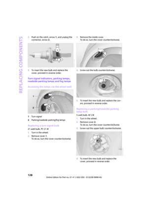 130
130 131
131 132
132 133
133 134
134 135
135 136
136 137
137 138
138 139
139 140
140 141
141 142
142 143
143 144
144 145
145 146
146 147
147 148
148 149
149 150
150 151
151 152
152 153
153 154
154 155
155 156
156 157
157 158
158 159
159 160
160 161
161 162
162 163
163 164
164 165
165 166
166 167
167 168
168 169
169 170
170 171
171 172
172 173
173 174
174 175
175
