2009 MERCEDES-BENZ GL SUV torque
[x] Cancel search: torquePage 18 of 309

Thermotronic
Malfunction indicator lamp ............234
Third brake lamp
Display message ............................ 226
Tightening torque .............................. 271
Time Setting (on-board computer) .......... 104
Setting the time (on-board com-
puter) ............................................. 104
TIREFIT kit
Using ............................................. 263
TopTether ............................................. 48
Total distance recorder ....................100
Tow-away protection ..........................55
Switching on/off (on-board com-
puter) ............................................. 109
Towing ................................................ 279
Towing eye Fitting ............................................ 278
Removing ....................................... 279
Trailer
7-pin connector ............................. 199
Coupling up .................................. 195
Decoupling ..................................... 196
Display message .................... 225, 226
Power supply ................................. 199
Trailer coupling
see Trailer tow hitch
Trailer loads
Technical data ............................... 298
Trailer tow hitch ................................ 193
Cleaning ......................................... 203
Trailer towing
Driving tips .................................... 196
ESP ®
................................................ 51
Malfunction ................................... .248
Mounting dimensions ....................297
Parktroni c...................................... 135
Transmission
Display message ............................ 216
Transmission output (maximum)
Telephone/two-way radio ..............285
Transmission positions ....................... 93
Transport (vehicle) ............................279
Travelling uphill ................................. 190
Trim strips Cleaning ......................................... 205 Trip computer
Menu (on-board computer) ............110
Trip computer (on-board com-
puter) ................................................. .110
Trip meter ............................................ 99
Resetting (on-board computer) ......110
Turn signal lamps
Display message ............................ 226
TV
Operating (on-board computer) .....101
Two-way radio
Installation ..................................... 285
Type identification plate
see vehicle identification plate ......286
Tyre
Direction of rotatio n...................... 180
Tyre grip ............................................. 188
Tyre pressure ................................... .180
Calling up (on-board computer) ....183
Display message ...........217, 218, 229
Tyre pressure loss warning system
............................................................ 182
Tyre pressure monitor
Warning lamp ................................. 237
Tyres
General notes ................................ 179
Technical data ....................... 296, 297
Tyre tread .......................................... .180 U
Unlocking Emergency unlocking ..................... 250
From the inside (central unlocking
button) ............................................. 59 V
Vanity mirror Sun visor ........................................ 162
Variable Speedtronic ........................126
Vehicle Emergency unlocking ............250, 251
Individual settings (on-board com-
puter) ............................................. 103
Leaving parked up .........................249
Towing ........................................... 279
Transporting .................................. 279 Index
15 X164_AKB; 2; 3, en-GB
wobuchh,
Version: 2.11.8.1
2009-03-31T14:14:58+02:00 - Seite 15Dateiname: 6515431202_buchblock.pdf; erzeugt am 01. Apr 2009 00:16:30; WK
Page 19 of 309

Vehicle battery
.................................. 272
Vehicle dimensions ...........................295
Vehicle electronics ...........................284
Vehicle identification number
(VIN) .................................................. 286
Vehicle identification plate ..............286
Vehicle level Display mes-
sage.............................................. 221, 222
Vehicle tool kit .................................. 209W
Warning and indicator lamps ABS (yellow) ................................... 235
ESP ®
........................................ 51, 236
LIM (cruise control) ........................ 118
LIM (Distronic) ............................... 121
LIM (variable Speedtronic) .............126
Malfunction indicator lamp ............234
Tyre pressure monitor ...................237
Warning tone ..................................... 239
Warning triangle ................................ 208
Washer fluid Display message ............................ 232
Washer fluid reservoir ..............178, 291
Filling capacity ............................... 291
Wearing seat belts .............................. 75
Wheel bolts Tightening torque ........................... 271
Wheel chock
Use ................................................ 268
Wheels
Cleaning ......................................... 202
General notes ................................ 179
Interchanging ................................. 184
Technical data ....................... 296, 297
Windowbag .......................................... 39
Windows Cleaning ......................................... 202
see Side windows
Windscreen
Infrared reflective .......................... 168
Windscreen washer fluid ..................291
Topping up ..................................... 178
Windscreen washer system .....178, 291 Windscreen wipers
.............................84
Malfunction ................................... .245
Replacing the wiper blades ............261
Winter diesel ..................................... 174
Winter driving ............................ 185, 186
Winter tyres ....................................... 185
Limiting the speed (on-board com-
puter) ............................................. 128
Wiper blades
Cleaning ......................................... 202
Replacing ....................................... 261
Wooden trim
Cleaning ......................................... 205 16
Index X164_AKB; 2; 3, en-GB
wobuchh,
Version: 2.11.8.1 2009-03-31T14:14:58+02:00 - Seite 16Dateiname: 6515431202_buchblock.pdf; erzeugt am 01. Apr 2009 00:16:30; WK
Page 55 of 309
the trailer from swerving and will thus be
unable to reduce the risk of an accident. Trail-
ers with a high centre of gravity can tip over
before ESP ®
can detect this.
Trailer stabilisation does not work if ESP ®
is
deactivated or disabled because of a mal-
function.
Activating/deactivating ESP ®ESP
®
is activated automatically when the
engine is running.
It may be best to deactivate ESP ®
in the fol-
lowing situations:
R when using snow chains
R in deep snow
R on sand or gravel G
Risk of accident
Activate ESP ®
as soon as the situations
described above no longer apply. ESP ®
will
otherwise not be able to stabilise the vehicle
if the vehicle starts to skid or a wheel starts
to spin.
If you deactivate ESP ®
:
R ESP ®
no longer improves driving stability.
R the engine's torque is no longer limited and
the drive wheels can spin. Spinning of the
wheels results in a cutting action, which
provides better grip.
R traction control is still activated.
R ESP ®
still provides support when you
brake.
i If ESP ®
is deactivated and one or more
wheels start to spin, the dwarning lamp
in the instrument cluster flashes. In such
situations, ESP ®
will not stabilise the vehi-
cle. X
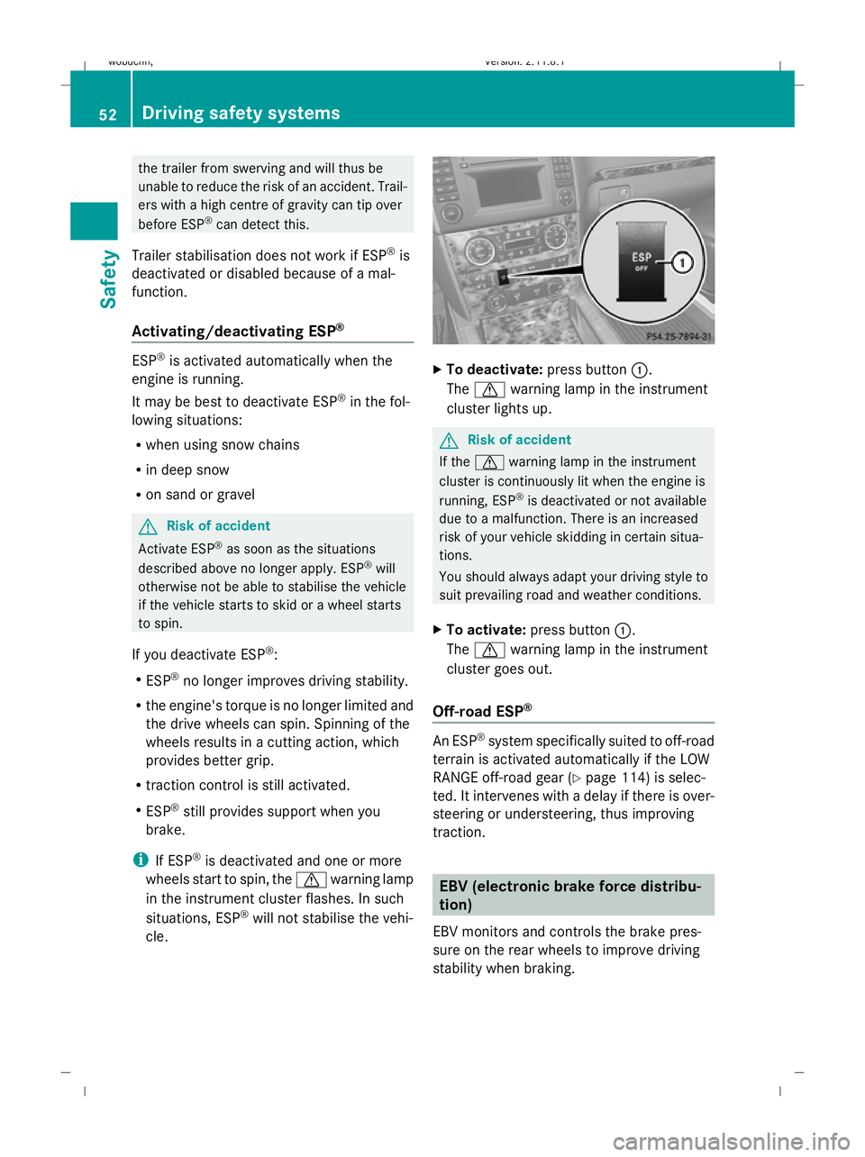
To deactivate: press button:.
The d warning lamp in the instrument
cluster lights up. G
Risk of accident
If the d warning lamp in the instrument
cluster is continuously lit when the engine is
running, ESP ®
is deactivated or not available
due to a malfunction. There is an increased
risk of your vehicle skidding in certain situa-
tions.
You should always adapt your driving style to
suit prevailing road and weather conditions.
X To activate: press button :.
The d warning lamp in the instrument
cluster goes out.
Off-road ESP ® An ESP
®
system specifically suited to off-road
terrain is activated automatically if the LOW
RANGE off-road gear (Y page 114) is selec-
ted. It intervenes with a delay if there is over-
steering or understeering, thus improving
traction. EBV (electronic brake force distribu-
tion)
EBV monitors and controls the brake pres-
sure on the rear wheels to improve driving
stability when braking. 52
Driving safety systemsSafety
X164_AKB; 2; 3, en-GB
wobuchh
,V ersion: 2.11.8.1
2009-03-31T14:14:58+02:00 - Seite 52
Dateiname: 6515431202_buchblock.pdf; erzeugt am 01. Apr 2009 00:16:49; WK
Page 117 of 309
Deactivating
X
Press button :.
Indicator lamp ;goes out.
The DSR symbol appears in the multi-func-
tion display with the Offmessage.
DSR switches off automatically if you drive
faster than 35 km/h. The DSR symbol
appears in the multi-function display with the
Off message. You also hear a warning tone.
Changing the set speed while the vehi-
cle is in motion When DSR is activated, you can change the
set speed to a value between 4 km/h and
18 km/h while the vehicle is in motion. X
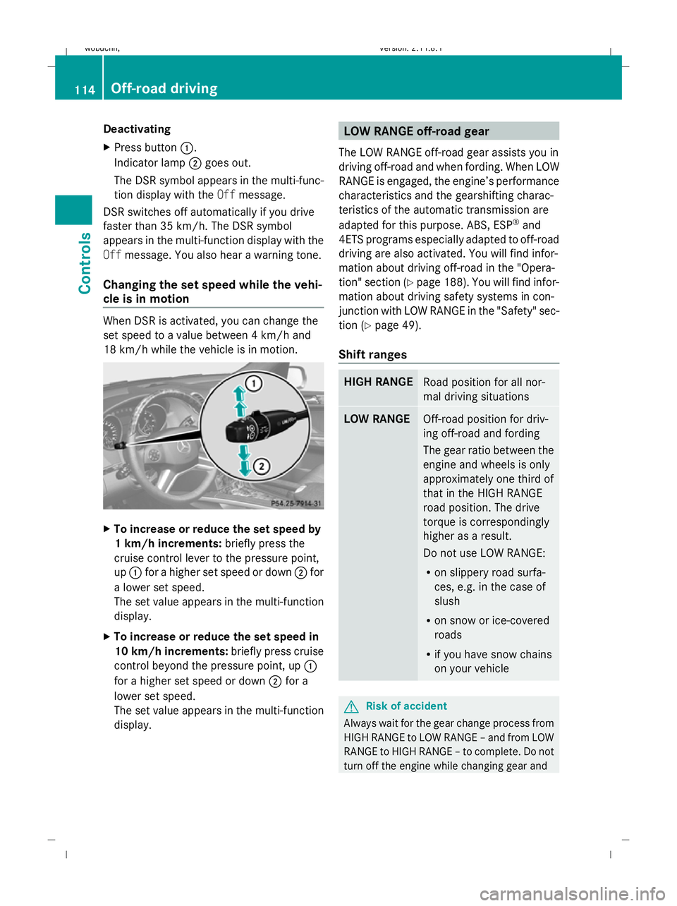
To increase or reduce the set speed by
1 km/h increments: briefly press the
cruise control lever to the pressure point,
up : for a higher set speed or down ;for
a lower set speed.
The set value appears in the multi-function
display.
X To increase or reduce the set speed in
10 km/h increments: briefly press cruise
control beyond the pressure point, up :
for a higher set speed or down ;for a
lower set speed.
The set value appears in the multi-function
display. LOW RANGE off-road gear
The LOW RANGE off-road gear assists you in
driving off-road and when fording. When LOW
RANGE is engaged, the engine’s performance
characteristics and the gearshifting charac-
teristics of the automatic transmission are
adapted for this purpose. ABS, ESP ®
and
4ETS programs especially adapted to off-road
driving are also activated. You will find infor-
mation about driving off-road in the "Opera-
tion" section (Y page 188). You will find infor-
mation about driving safety systems in con-
junction with LOW RANGE in the "Safety" sec-
tion (Y page 49).
Shift ranges HIGH RANGE
Road position for all nor-
mal driving situations
LOW RANGE
Off-road position for driv-
ing off-road and fording
The gear ratio between the
engine and wheels is only
approximately one third of
that in the HIGH RANGE
road position. The drive
torque is correspondingly
higher as a result.
Do not use LOW RANGE:
R on slippery road surfa-
ces, e.g. in the case of
slush
R on snow or ice-covered
roads
R if you have snow chains
on your vehicle G
Risk of accident
Always wait for the gear change process from
HIGH RANGE to LOW RANGE – and from LOW
RANGE to HIGH RANGE – to complete. Do not
turn off the engine while changing gear and 114
Off-road drivingCont
rols
X164_AKB; 2; 3, en-GB
wobuchh, Version: 2.11.8.1 2009-03-31T14:14:58+02:00 - Seite 114
Dateiname: 6515431202_buchblock.pdf; erzeugt am 01. Apr 2009 00:17:19; WK
Page 187 of 309

board computer refer to those measured at
sea level. At high altitudes, the tyre pres-
sure values indicated by a pressure gauge
are higher than those shown by the on-
board computer. In this case, do not reduce
the tyre pressures.
i After a teach-in period, the tyre pressure
monitor automatically recognises new
wheels or new sensors. As long as a clear
allocation of the tyre pressure values to the
individual wheels is not possible, the dis-
play message Tyre pressure monitor
active is shown instead of the tyre pres-
sure display. The tyre pressures are already
being monitored.
Restarting the tyre pressure monitor When you restart the tyre pressure monitor,
all existing warning messages are deleted and
the warning lamps go out. The monitor uses
the currently set tyre pressures as the speci-
fied values for monitoring.
In most cases, the tyre pressure monitor will
automatically detect the new reference val-
ues, e.g. if you have:
R changed the tyre pressure
R changed the wheels or tyres
R fitted new wheels or tyres
i You will find the menu overview on
(Y page 99).
If you wish to define the new reference values
manually:
X Use the table on the inside of the fuel filler
flap to ensure that the tyre pressure is set
correctly in all four tyres for the current
operating conditions.
Also observe the notes in the section on
tyre pressures (Y page 180).
X Make sure that the key is in position 2in
the ignition lock.
X Press the &or* button to select the
Tyre pressure function or wait until the
following message appears: X
Press the reset button on the instrument
cluster (Y page 25).
The multi-function display shows the mes-
sage:
Restart tyre pressure monitor?
Yes Cancel
X Press the Wbutton.
The multi-function display shows the mes-
sage:
Tyre pressure monitor restarted
The tyre pressure monitor has stored the
pressure of the tyres as a new reference
value.
Cancelling the restart X
Press the Xbutton.
Other messages in the multi-function
display If in multi-function display the following mes-
sage appears:
Please correct tyre pressures
X
Check the tyre pressure on all four wheels
and correct it if necessary.
i If the wheel positions on the vehicle are
interchanged, the tyre pressures may be
displayed for the wrong positions for a
short time. This is rectified after a few
minutes of driving, and the tyre pressures
are displayed for the correct positions. Interchanging the wheels
G
Risk of accident
Interchange the front and rear wheels only if
they have the same dimensions: for example
size, offset, etc.
After a wheel is changed, have the tightening
torque checked at a specialist workshop that
has the necessary specialist knowledge and
tools to carry out the work required.
Mercedes-Benz recommends that you use a 184
Tyres and wheelsOperation
X164_AKB; 2; 3, en-GB
wobuchh,
Version: 2.11.8.1 2009-03-31T14:14:58+02:00 - Seite 184
Dateiname: 6515431202_buchblock.pdf; erzeugt am 01. Apr 2009 00:17:48; WK
Page 188 of 309
Mercedes-Benz Service Centre for this pur-
pose. In particular, work relevant to safety or
on safety-related systems must be carried out
at a qualified specialist workshop.
The wheels could work loose if they are not
tightened to a torque of 150 Nm.
For safety reasons, Mercedes-Benz recom-
mends that you only use wheel bolts of the
correct size which have been approved for
Mercedes-Benz vehicles.
The wear patterns on the front and rear tyres
differ, depending on the operating conditions.
Interchange the wheels before a clear wear
pattern has formed on the tyres. Front tyres
typically wear more on the shoulders and the
rear tyres in the centre.
On vehicles that have the same size front and
rear wheels you can interchange the wheels
every 5,000 km to 10,000 km depending on
the degree of tyre wear. Do not reverse the
direction of tyre rotation.
Clean the contact surfaces of the wheel and
the brake disc thoroughly every time a wheel
is interchanged. Check the tyre pressure and,
if necessary, restart the tyre pressure loss
warning system or the tyre pressure moni-
tor*.
! On vehicles fitted with a tyre pressure
monitor*, electronic components are loca-
ted in the wheel.
Tyre-fitting tools should not be applied in
the area of the valve, as this could damage
the electronic components.
Always have the wheels interchanged/
changed at a qualified specialist workshop,
e.g. a Mercedes-Benz Service Centre.
i Vehicles with a tyre pressure monitor*
If the positions of the wheels on the vehicle
are changed, the tyre pressure may be tem-
porarily displayed in the wrong position.
This is rectified after a few minutes of driv-
ing; the tyre pressures are then displayed
in the correct positions. Winter driving
Points to remember
Have your vehicle winterproofed at a qualified
specialist workshop, e.g. at a Mercedes-Benz
Service Centre, at the onset of winter.
Observe the notes in the "Changing a wheel"
section (Y page 184). Winter tyres
At temperatures below +7 ˚C always use all-
weather tyres or winter tyres and always use
winter tyres in winter road conditions. Only
winter tyres displaying the isnowflake
symbol in addition to the M+S marking pro-
vide optimum grip in wintry road conditions.
Only these tyres will allow the ABS and
ESP ®
driving systems to function optimally in
winter, as these tyres have been designed
specifically for driving in snow.
Use winter tyres of the same make and tread
on all wheels to maintain safe handling char-
acteristics. G
Risk of accident
Winter tyres with a tread depth of less than
4 mm must be replaced immediately. They are
no longer suitable for winter use and can no
longer provide sufficient grip. This could
cause you to lose control of your vehicle and
cause an accident.
Always observe the maximum permissible
speed specified for the winter tyres you have
fitted. If you fit winter tyres which have a
lower maximum permissible speed than that
of the vehicle, affix an appropriate warning
sign in the driver's field of vision. This can be
obtained at a qualified specialist workshop,
e.g. from a Mercedes-Benz Service Centre.
Under these circumstances, you should also
restrict the maximum speed of the vehicle
using permanent Speedtronic 27
to the maxi-
27 Only available for certain countries. Winter driving
185Operation
* optional
X164_AKB; 2; 3, en-GB
wobuchh,
Version: 2.11.8.1 2009-03-31T14:14:58+02:00 - Seite 185 Z
Dateiname: 6515431202_buchblock.pdf; erzeugt am 01. Apr 2009 00:17:48; WK
Page 194 of 309
R
Accelerate gently and make sure that the
wheels are gripping.
R Avoid high engine speeds, except when
driving on sandy and muddy routes with
high driving resistance.
R Select a shift range appropriate to the gra-
dient.
R Before tackling steep downhill gradients,
select shift range 1.
i The vehicle will not roll backwards when
stopping on an uphill gradient if:
R the automatic transmission is in position
D.
R you have selected the LOW RANGE off-
road gear.
Depress the brake pedal when stopping on
steep uphill gradients. Hill start assist will
aid you when you pull away again
(Y page 90).
Maximum gradient-climbing capability On good road surfaces and with the LOW
RANGE off-road gear selected, the full gradi-
ent-climbing capability is available.
i
If the load on the front axle is reduced
when pulling away on a steep uphill slope,
the front wheels have a tendency to spin.
4ETS recognises this and brakes the
wheels accordingly. The rear wheel torque
is increased and it is easier to pull away.
Brow of hill When driving up an uphill gradient, slightly
reduce pressure on the accelerator immedi-
ately before reaching the brow of the hill.
Make use of the vehicle’s own impetus to
travel over the brow.
This style of driving prevents: R
the vehicle from lifting off the ground on the
brow of a hill
R loss of traction
R the vehicle from travelling too quickly down
the other side
Driving downhill R
Drive slowly.
R Do not drive at an angle down steep
inclines. Steer into the line of fall and drive
with the front wheels aligned straight. Oth-
erwise, the vehicle could slip sideways, tip
and overturn.
R Before tackling steep downhill gradients,
select shift range 1.
R Activate DSR. If this is not sufficient, brake
gently. When doing so, make sure that the
vehicle is facing in the direction of the line
of fall.
R Check that the brakes are working normally
after a long downhill stretch.
i Off-road ABS is activated when the
LOW RANGE off-road gear is selected.
At speeds below 30 km/h, the front wheels
lock cyclically during braking. The digging-
in effect achieved in the process reduces
the stopping distance when driving off-
road. The steerability of the vehicle is con-
siderably reduced when the wheels lock. Driving over obstacles
Observe the following rules when driving over
tree stumps, large stones and other obsta-
cles:
R Select the LOW RANGE off-road gear
(Y page 114).
R Avoid high engine speeds.
R Select shift range 1. Off-road driving
191Operation
X164_AKB; 2; 3, en-GB
wobuchh,V ersion: 2.11.8.1
2009-03-31T14:14:58+02:00 - Seite 191 Z
Dateiname: 6515431202_buchblock.pdf; erzeugt am 01. Apr 2009 00:17:49; WK
Page 274 of 309
!
Always use wheel bolts ;to fit the
"Minispare" emergency spare wheel*.
Using other wheel bolts to fit the
"Minispare" emergency spare wheel* could
damage the brake system.
i Wheel bolts 2can be found with the
"Minispare" emergency spare wheel*.
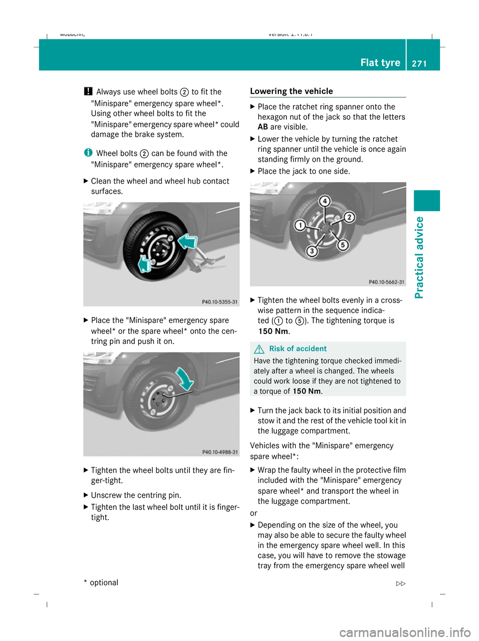
X Clean the wheel and wheel hub contact
surfaces. X
Place the "Minispare" emergency spare
wheel* or the spare wheel* onto the cen-
tring pin and push it on. X
Tighten the wheel bolts until they are fin-
ger-tight.
X Unscrew the centring pin.
X Tighten the last wheel bolt until it is finger-
tight. Lowering the vehicle X
Place the ratchet ring spanner onto the
hexagon nut of the jack so that the letters
AB are visible.
X Lower the vehicle by turning the ratchet
ring spanner until the vehicle is once again
standing firmly on the ground.
X Place the jack to one side. X
Tighten the wheel bolts evenly in a cross-
wise pattern in the sequence indica-
ted (: toA). The tightening torque is
150 Nm. G
Risk of accident
Have the tightening torque checked immedi-
ately after a wheel is changed. The wheels
could work loose if they are not tightened to
a torque of 150 Nm.
X Turn the jack back to its initial position and
stow it and the rest of the vehicle tool kit in
the luggage compartment.
Vehicles with the "Minispare" emergency
spare wheel*:
X Wrap the faulty wheel in the protective film
included with the "Minispare" emergency
spare wheel* and transport the wheel in
the luggage compartment.
or
X Depending on the size of the wheel, you
may also be able to secure the faulty wheel
in the emergency spare wheel well. In this
case, you will have to remove the stowage
tray from the emergency spare wheel well Flat tyre
271Practical advice
* optional
X164_AKB; 2; 3, en-GB
wobuchh,
Version: 2.11.8.1 2009-03-31T14:14:58+02:00 - Seite 271 Z
Dateiname: 6515431202_buchblock.pdf; erzeugt am 01. Apr 2009 00:18:13; WK