2009 MERCEDES-BENZ E-CLASS SALOON set clock
[x] Cancel search: set clockPage 180 of 373

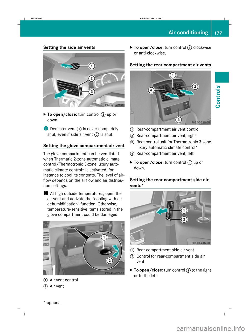
Setting the side air vents
X
To open/close: turn control=up or
down.
i Demister vent :is never completely
shut, even if side air vent ;is shut.
Setting the glove compartment air vent The glove compartment can be ventilated
when Thermatic 2-zone automatic climate
control/Thermotronic 3-zone luxury auto-
matic climate control* is activated, for
instance to cool its contents. The level of air-
flow depends on the airflow and air distribu-
tion settings.
!
At high outside temperatures, open the
air vent and activate the "cooling with air
dehumidification" function. Otherwise,
temperature-sensitive items stored in the
glove compartment could be damaged. :
Air vent control
; Air vent X
To open/close: turn control:clockwise
or anti-clockwise.
Setting the rear-compartment air vents :
Rear-compartment air vent control
; Rear-compartment air vent, right
= Rear control unit for Thermotronic 3-zone
luxury automatic climate control*
? Rear-compartment air vent, left
X To open/close: turn control:up or
down.
Setting the rear-compartment side air
vents* :
Rear-compartment side air vent
; Control for rear-compartment side air
vent
X To open/close: turn control;to the right
or to the left. Air conditioning
177Controls
* optional
212_AKB; 2; 4, en-GB
mkalafa,
Version: 2.11.8.1 2009-05-05T14:17:16+02:00 - Seite 177 Z
Dateiname: 6515346702_buchblock.pdf; erzeugt am 07. May 2009 14:16:30; WK
Page 238 of 373

X
Grasp release wheel ;with your hand
such that the thumb is in the thumb rest
and turn it anti-clockwise.
The ball coupling disengages and folds out
from under the rear bumper. Indicator
lamp :flashes. X
Pull the ball coupling in the direction of the
arrow until it engages in a vertical position.
Indicator lamp :goes out.
The multi-function display shows the
Trailer hitch Check lock mech. mes-
sage until the ball coupling is engaged.
X Remove the protective cap from the ball
coupling and store it in a safe place.
X Make sure that the ball of the ball coupling
is clean and that, depending on the trailer
specification, it is greased or dry (without
grease) when used.
The power socket is integrated in the ball
coupling. Notes on towing a trailer
G
Risk of accident
When reversing the vehicle towards the
trailer, make sure there is nobody between
the trailer and the vehicle.
Couple and uncouple the trailer carefully. If
you do not couple the trailer to the towing
vehicle correctly, the trailer could become
detached. Make sure that the following values are not
exceeded:
R
the permissible trailer drawbar noseweight
R the permissible trailer load
R the permissible rear axle load of the towing
vehicle
R the maximum permissible gross vehicle
weight of both the towing vehicle and the
trailer
You will find the applicable permissible val-
ues, which must not be exceeded, in the vehi-
cle documents.
You will find the values approved by the man-
ufacturer on the vehicle identification plates
and those for the towing vehicle in the "Tech-
nical data" section.
i When towing a trailer, set the tyre pres-
sure on the rear axle of the towing vehicle
for a maximum load; see the tyre pressure
table in the fuel filler flap.
You will find installation dimensions and loads
in the "Technical data" section
(Y page 356).
The maximum drawbar load of the trailer
drawbar on the ball coupling is 84 kg. How-
ever, the actual noseweight must not exceed
the value given on the trailer coupling or
trailer identification plates. The lowest weight
applies.
! Use a noseweight as close as possible to
the maximum permissible noseweight. Do
not use a noseweight of less than 50 kg,
otherwise the trailer may come loose.
Bear in mind that the payload and the rear
axle load are reduced by the actual nose-
weight.
Please note that when towing a trailer, PARK-
TRONIC* ( Ypage 159), parking guid-
ance* (Y page 162) and Blind Spot
Assist* (Y page 261) are only available with
limitations, or not at all. Trailer towing
235Operation
* optional
212_AKB; 2; 4, en-GB
mkalafa
,V ersion: 2.11.8.1
2009-05-05T14:17:16+02:00 - Seite 235 Z
Dateiname: 6515346702_buchblock.pdf; erzeugt am 07. May 2009 14:16:59; WK
Page 242 of 373

X
Open the socket cover.
X Insert connector with lug :into
groove ;on the socket and turn the con-
nector clockwise to the stop.
X Make the cover engage.
X If you are using an adapter cable, secure
the cable to the trailer with cable ties.
! Make sure that there is sufficient cable
play so that the cable cannot become
detached when cornering. Service
ASSYST PLUS service interval display
The ASSYST PLUS service interval display
informs you of the next service due date.
The service due date is shown in the multi-
function display, for example:
Next service A in .. days
Next service A in ... km
Service A due
The letter indicates which service is due. A
stands for a minor service and Bfor a major
service. A number or another letter may be
displayed after the letter. This figure indicates
any necessary additional maintenance work
to be performed. If you report this displayed
information to a qualified specialist work-
shop, for example a Mercedes-Benz Service
Centre, they can inform you of the costs the
service will incur.
The ASSYST PLUS service interval display
does not take into account any periods of
time during which the battery is disconnec-
ted. Maintaining the time-dependent service
schedule:
X
Note down the service due date displayed
before disconnecting the battery.
or
X Subtract the battery disconnection periods
from the service date shown on the display
after reconnecting the battery.
Hiding a service message X
Press %ora on the steering wheel.
Service overdue A display message is shown in the multi-func-
tion display, for example:
Service A overdue by ... days
Service A overdue by .. km
i
If you fail to have the service performed
by the specified date, you may be violating
applicable laws. Your warranty may be inva-
lidated and goodwill settlements may be
refused.
Calling up a service due date X
Switch on the ignition.
X Press =or; to select the Service
menu on the steering wheel.
X Press 9or: to select the ASSYST
PLUS submenu and press ato confirm.
The multi-function display shows the
service due date. AdBlue
®
service indicator
i For Blue-TEC vehicles only.
The BlueTEC exhaust gas aftertreatment
must be operated with a reducing agent
(AdBlue ®
) in order for it to function correctly.
AdBlue ®
is topped up as part of maintenance
work. Under normal operating conditions, a
full tank of AdBlue ®
should last until the next
service due date. Service
239Operation
212_AKB; 2; 4, en-GB
mkalafa, Version: 2.11.8.1 2009-05-05T14:17:16+02:00 - Seite 239 Z
Dateiname: 6515346702_buchblock.pdf; erzeugt am 07. May 2009 14:17:01; WK
Page 311 of 373

Turn signal lamp (halogen headlamps)
Due to their location, have the bulbs in the
left-hand headlamp changed at a qualified
specialist workshop, e.g. a Mercedes-Benz
Service Centre.
X Switch off the lights.
X Open the bonnet.
X Turn bulb holder :anti-clockwise and
remove it.
X Turn the bulb anti-clockwise, applying
slight pressure, and remove it from bulb
holder :.
X Insert the new bulb into bulb holder :and
turn it clockwise.
X Insert bulb holder :and turn it clockwise. Replacing the wiper blades
Windscreen wiper blades
G
Risk of accident
The windscreen will no longer be wiped prop-
erly if the wiper blades are worn. This could
prevent you from observing the traffic condi-
tions, thereby causing an accident. Replace
the wiper blades twice a year, ideally in spring
and autumn. G
Risk of accident
The wiper arms could start moving and cause
an injury if you leave the windscreen wipers
switched on. Remove the key from the ignition lock before
replacing the wiper blades.
! To avoid damaging the windscreen wiper
blades, make sure that you touch only the
wiper arm of the windscreen wiper.
To remove X
Remove the key from the ignition lock or
turn the key to position 0(KEYLESS GO).
X Fold the wiper arm away from the wind-
screen until it engages.
X Set the wiper blade at right angles to the
wiper arm. X
Remove the wiper blade from the retainer
on the wiper arm in the direction of the
arrow.
Fitting !
The two wiper blades are different
lengths. If you swap the wiper blades they
may scratch the windscreen. Make sure
that the longer wiper blade is fitted on the
driver's side.
X Compare the lengths of the two new wiper
blades.
X Slide the longer of the two new wiper
blades into the retainer on the wiper arm
on the driver's side in the opposite direc-
tion to the arrow.
X Repeat the same procedure on the front-
passenger's side with the shorter of the two
new wiper blades. 308
Replacing the
wiper bladesPractical advice
212_AKB; 2; 4, en-GB
mkalafa, Version: 2.11.8.1 2009-05-05T14:17:16+02:00 - Seite 308
Dateiname: 6515346702_buchblock.pdf; erzeugt am 07. May 2009 14:17:19; WK