2009 KIA SOUL ESP
[x] Cancel search: ESPPage 289 of 328
Maintenance
48
7
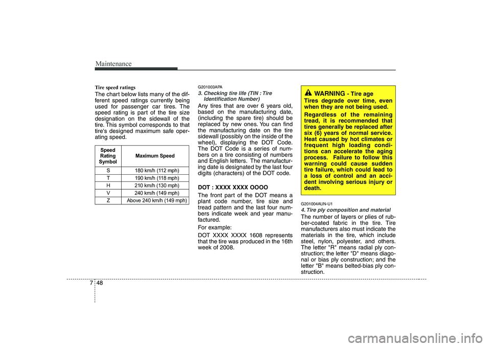
Tire speed ratings
The chart below lists many of the dif-
ferent speed ratings currently being
used for passenger car tires. The
speed rating is part of the tire size
designation on the sidewall of the
tire. This symbol corresponds to that
tire's designed maximum safe oper-ating speed. G201003APA
3. Checking tire life (TIN : Tire
Identification Number)
Any tires that are over 6 years old,
based on the manufacturing date,(including the spare tire) should be
replaced by new ones. You can find
the manufacturing date on the tire
sidewall (possibly on the inside of the
wheel), displaying the DOT Code.
The DOT Code is a series of num-
bers on a tire consisting of numbers
and English letters. The manufactur-
ing date is designated by the last four
digits (characters) of the DOT code.
DOT : XXXX XXXX OOOO
The front part of the DOT means a
plant code number, tire size and
tread pattern and the last four num-
bers indicate week and year manu-
factured.
For example:
DOT XXXX XXXX 1608 represents
that the tire was produced in the 16th
week of 2008. G201004AUN-U1
4. Tire ply composition and material
The number of layers or plies of rub-
ber-coated fabric in the tire. Tire
manufacturers also must indicate the
materials in the tire, which include
steel, nylon, polyester, and others.
The letter "R" means radial ply con-
struction; the letter "D" means diago-
nal or bias ply construction; and theletter "B" means belted-bias ply con-
struction.
S 180 km/h (112 mph)
T 190 km/h (118 mph)
H 210 km/h (130 mph)
V 240 km/h (149 mph) Z Above 240 km/h (149 mph)
Maximum Speed
Speed
Rating
Symbol
WARNING - Tire age
Tires degrade over time, even
when they are not being used.
Regardless of the remaining
tread, it is recommended that
tires generally be replaced after
six (6) years of normal service.
Heat caused by hot climates orfrequent high loading condi-
tions can accelerate the aging
process. Failure to follow this
warning could cause sudden
tire failure, which could lead to
a loss of control and an acci-
dent involving serious injury ordeath.
Page 290 of 328

749
Maintenance
G201005AUN
5. Maximum permissible inflationpressure
This number is the greatest amount of air pressure that should be put in
the tire. Do not exceed the maximum
permissible inflation pressure. Refer
to the Tire and Loading Information
label for recommended inflation
pressure.
G201006AUN
6. Maximum load rating
This number indicates the maximum
load in kilograms and pounds that
can be carried by the tire. When
replacing the tires on the vehicle,
always use a tire that has the same
load rating as the factory installed
tire. G2010007AEN
7. Uniform tire quality grading
Quality grades can be found where
applicable on the tire sidewall
between tread shoulder and maxi-
mum section width.
For example:
TREAD wear 200
TRACTION AA
TEMPERATUE A
Tread wear
The tread wear grade is a compara-
tive rating based on the wear rate ofthe tire when tested under controlled
conditions on a specified govern-
ment test course. For example, a tire
graded 150 would wear one-and-a-
half times (1½) as well on the gov-
ernment course as a tire graded 100.
The relative performance of tires depends upon the actual conditions
of their use, however, and may
depart significantly from the norm
due to variations in driving habits,
service practices and differences in
road characteristics and climate.These grades are molded on the
side-walls of passenger vehicle tires.
The tires available as standard or
optional equipment on your vehicle
may vary with respect to grade.
Traction - AA, A, B & C
The traction grades, from highest to
lowest, are AA, A, B and C. Those
grades represent the tire’s ability to
stop on wet pavement measuredunder controlled conditions on spec-
ified government test surfaces of
asphalt and concrete. A tire marked
C may have poor traction perform-
ance.
WARNING
The traction grade assigned to this tire is based on straight-ahead braking traction tests,
and does not include accelera-
tion, cornering, hydroplaning,
or peak traction characteristics.
Page 297 of 328
Maintenance
56
7
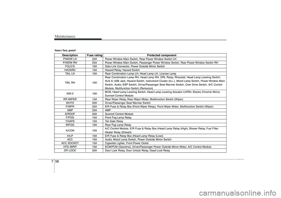
Inner fuse panel
Description Fuse rating Protected component
P/WDW LH 25A Power Window Main Switch, Rear Power Window Switch LH
P/WDW RH 25A Power Window Main Switch, Passenger Power Window Switch, Rear Power Window Switch RH FOLD'G 10A Data Link Connector, Power Outside Mirror Switch
HAZARD 15A Hazard Relay, Hazard Switch TAIL LH 10A Rear Combination Lamp LH, Head Lamp LH, License Lamp
TAIL RH 10A Rear Combination Lamp RH, Head Lamp RH, DRL Relay, Rheostat, Head Lamp Leveling Switch,
AUX & USB Jack, Hazard Switch, Instrument Cluster (ILL.), Mood Lamp Switch, Power Window Main
Switch, Audio, ESP Switch, Driver/Passenger Seat Warmer Switch, Over Drive Switch, A/C Control
Module, Multifunction Switch (Remocon)
IGN 2 10A BCM, Head Lamp Leveling Switch, Head Lamp Leveling Actuator LH/RH, Electro Chromic Mirror,Sunroof Control Module
RR WIPER 15A Rear Wiper Relay, Rear Wiper Motor, Multifunction Switch (Wiper) S/HTD 20A Driver/Passenger Seat Warmer Switch
F/WPR 25A E/R Fuse & Relay Box (Front Wiper Relay), Front Wiper Motor, Multifunction Switch (Wiper) AMP 25A AMP
S/ROOF 20A Sunroof Control Module F/FOG 15A Front Fog Lamp Relay
T/GATE 15A Tail Gate Relay R/FOG 10A Rear Fog Lamp Relay
A/CON 10A A/C Control Module, E/R Fuse & Relay Box (Head Lamp Relay (High), Blower Relay, Fuel Filter
Heater Relay (Diesel))
H/LP 10A E/R Fuse & Relay Box (Head Lamp Relay (Low)) ACC 10A Audio, Mood Lamp Switch, Power Outside Mirror Switch
ACC SOCKET 15A Cigarette Lighter, Front Power Outlet HTD MIRR 10A ECM/PCM (Gasoline), Driver/Passenger Power Outside Mirror Motor, A/C Control ModuleDR LOCK 20A Door Lock Relay, Door Unlock Relay, Dead Lock Relay
Page 298 of 328
757
Maintenance
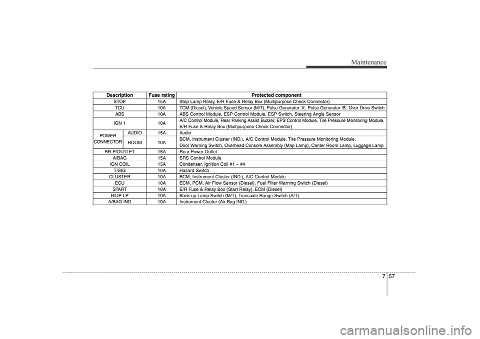
Description Fuse rating Protected componentSTOP 15A Stop Lamp Relay, E/R Fuse & Relay Box (Multipurpose Check Connector)TCU 10A TCM (Diesel), Vehicle Speed Sensor (M/T), Pulse Generator 'A', Pulse Generator 'B', Over Drive SwitchABS 10A ABS Control Module, ESP Control Module, ESP Switch, Steering Angle Sensor
IGN 1 10A A/C Control Module, Rear Parking Assist Buzzer, EPS Control Module, Tire Pressure Monitoring Module,
E/R Fuse & Relay Box (Multipurpose Check Connector)
AUDIO 15A Audio
ROOM 10A BCM, Instrument Cluster (IND.), A/C Control Module, Tire Pressure Monitoring Module,
Door Warning Switch, Overhead Console Assembly (Map Lamp), Center Room Lamp, Luggage Lamp
RR P/OUTLET 15A Rear Power Outlet A/BAG 15A SRS Control Module
IGN COIL 15A Condenser, Ignition Coil #1 ~ #4 T/SIG 10A Hazard Switch
CLUSTER 10A BCM, Instrument Cluster (IND.), A/C Control Module ECU 10A ECM, PCM, Air Flow Sensor (Diesel), Fuel Filter Warning Switch (Diesel)
START 10A E/R Fuse & Relay Box (Start Relay), ECM (Diesel)
B/UP LP 10A Back-up Lamp Switch (M/T), Transaxle Range Switch (A/T)
A/BAG IND 10A Instrument Cluster (Air Bag IND.)
POWER
CONNECTOR
Page 299 of 328
Maintenance
58
7
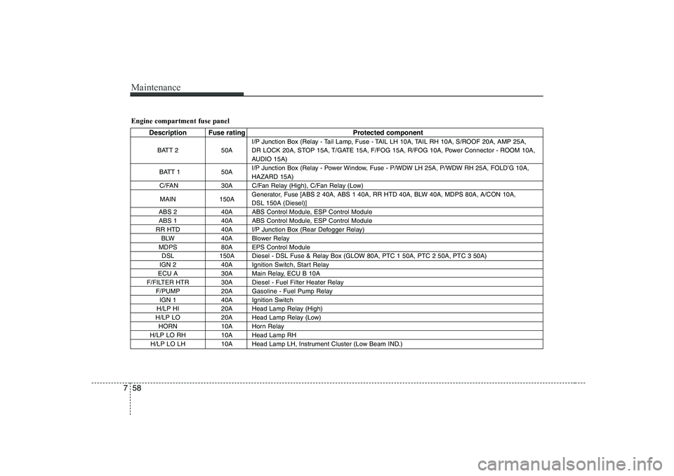
Engine compartment fuse panel
Description Fuse rating Protected component
BATT 2 50A I/P Junction Box (Relay - Tail Lamp, Fuse - TAIL LH 10A, TAIL RH 10A, S/ROOF 20A, AMP 25A,
DR LOCK 20A, STOP 15A, T/GATE 15A, F/FOG 15A, R/FOG 10A, Power Connector - ROOM 10A,
AUDIO 15A)
BATT 1 50A I/P Junction Box (Relay - Power Window, Fuse - P/WDW LH 25A, P/WDW RH 25A, FOLD'G 10A,HAZARD 15A)
C/FAN 30A C/Fan Relay (High), C/Fan Relay (Low)
MAIN 150A Generator, Fuse [ABS 2 40A, ABS 1 40A, RR HTD 40A, BLW 40A, MDPS 80A, A/CON 10A, DSL 150A (Diesel)]
ABS 2 40A ABS Control Module, ESP Control Module
ABS 1 40A ABS Control Module, ESP Control Module
RR HTD 40A I/P Junction Box (Rear Defogger Relay) BLW 40A Blower Relay
MDPS 80A EPS Control Module DSL 150A Diesel - DSL Fuse & Relay Box (GLOW 80A, PTC 1 50A, PTC 2 50A, PTC 3 50A)
IGN 2 40A Ignition Switch, Start Relay
ECU A 30A Main Relay, ECU B 10A
F/FILTER HTR 30A Diesel - Fuel Filter Heater Relay F/PUMP 20A Gasoline - Fuel Pump RelayIGN 1 40A Ignition Switch
H/LP HI 20A Head Lamp Relay (High)
H/LP LO 20A Head Lamp Relay (Low) HORN 10A Horn Relay
H/LP LO RH 10A Head Lamp RH H/LP LO LH 10A Head Lamp LH, Instrument Cluster (Low Beam IND.)
Page 301 of 328
Maintenance
60
7
LIGHT BULBS
G220000AUN
Use only the bulbs of the specified wattage.
✽✽ NOTICE
After heavy, driving rain or washing, headlight and taillight lenses could
appear frosty. This condition is caused by
the temperature difference between the
lamp inside and outside. This is similar
to the condensation on your windows
inside your vehicle during the rain and
doesn’t indicate a problem with your
vehicle. If the water leaks into the lamp
bulb circuitry, have the vehicle checked
by an authorized KIA dealer.
G220100APB(UN-KM)
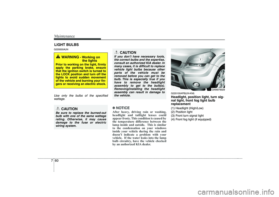
Headlight, position light, turn sig-
nal light, front fog light bulbreplacement
(1) Headlight (High/Low)
(2) Position light
(3) Front turn signal light
(4) Front fog light (if equipped)
WARNING - Working on
the lights
Prior to working on the light, firmly
apply the parking brake, ensure
that the ignition switch is turned tothe LOCK position and turn off the
lights to avoid sudden movement
of the vehicle and burning your fin-
gers or receiving an electric shock.
CAUTION
Be sure to replace the burned-out bulb with one of the same wattage rating. Otherwise, it may cause damage to the fuse or electricwiring system.
CAUTION
If you don’t have necessary tools,
the correct bulbs and the expertise,consult an authorized KIA dealer. In many cases, it is difficult to replace
vehicle light bulbs because otherparts of the vehicle must be removed before you can get to the bulb. This is especially true if you
have to remove the headlight assembly to
get to the bulb(s).
Removing/installingthe headlight
assembly can result in damage to the vehicle.OAM079029
Page 315 of 328
Maintenance
74
7
EMISSION CONTROL SYSTEM
G270000AUN
The emission control system of your
vehicle is covered by a written limited
warranty. Please see the warranty infor-
mation contained in the Warranty &
Maintenance booklet in your vehicle.
Your vehicle is equipped with an emis- sion control system to meet all emission
regulations. There are three emission control sys-
tems which are as follows.
(1) Crankcase emission control system
(2) Evaporative emission control system(3) Exhaust emission control system In order to assure the proper function of
the emission control systems, it is rec-
ommended that you have your vehicle
inspected and maintained by an author-
ized KIA dealer in accordance with the
maintenance schedule in this manual. Caution for the Inspection and
Maintenance Test (With Electronic
Stability Program (ESP) system)
To prevent the vehicle from misfir-
ing during dynamometer testing,
turn the Electronic Stability
Program (ESP) system off by press-
ing the ESP switch.
After dynamometer testing is com- pleted, turn the ESP system back on
by pressing the ESP switch again. G270100AUN
1. Crankcase emission control
system
The positive crankcase ventilation sys-
tem is employed to prevent air pollution
caused by blow-by gases being emitted
from the crankcase. This system supplies
fresh filtered air to the crankcase through
the air intake hose. Inside the crankcase,
the fresh air mixes with blow-by gases,
which then pass through the PCV valveinto the induction system.
G270200AUN-C1
2. Evaporative emission control system
The Evaporative Emission Control
System is designed to prevent fuel
vapors from escaping into the atmos-
phere.
Page 322 of 328
85
Specifications & Consumer information
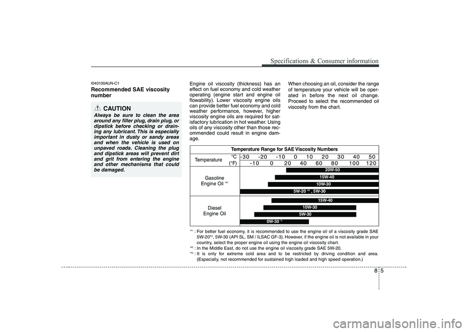
I040100AUN-C1 Recommended SAE viscosity
number Engine oil viscosity (thickness) has an
effect on fuel economy and cold weather
operating (engine start and engine oil
flowability). Lower viscosity engine oils
can provide better fuel economy and cold
weather performance, however, higher
viscosity engine oils are required for sat-
isfactory lubrication in hot weather. Using
oils of any viscosity other than those rec-ommended could result in engine dam-
age.When choosing an oil, consider the range
of temperature your vehicle will be oper-
ated in before the next oil change.Proceed to select the recommended oil
viscosity from the chart.
CAUTION
Always be sure to clean the area
around any filler plug, drain plug, ordipstick before checking or drain- ing any lubricant. This is especially
important in dusty or sandy areasand when the vehicle is used on unpaved roads. Cleaning the plugand dipstick areas will prevent dirt
and grit from entering the engineand other mechanisms that could be damaged.
Temperature Range for SAE Viscosity Numbers
Temperature
Gasoline
Engine Oil *
1
°C
(°F)-30 -20 -10 0 10 20 30 40 50 -10 0 20 40 60 80 100 120
Diesel
Engine Oil
5W-30
15W-40
10W-30
0W-30 *3
*1
: For better fuel economy, it is recommended to use the engine oil of a viscosity grade SAE
5W-20* 2
, 5W-30 (API SL, SM / ILSAC GF-3). However, if the engine oil is not available in your
country, select the proper engine oil using the engine oil viscosity chart.
* 2
: In the Middle East, do not use the engine oil viscosity grade SAE 5W-20.
* 3
: It is only for extreme cold area and to be restricted by driving condition and area.
(Especially, not recommended for sustained high loaded and high speed operation.)
20W-50
10W-30
15W-40
5W-20 * 2
, 5W-30