2009 KIA SOUL fuel filter
[x] Cancel search: fuel filterPage 262 of 328
721
Maintenance
EXPLANATION OF SCHEDULED MAINTENANCE ITEMS
G050100AUN Engine oil and filter The engine oil and filter should be
changed at the intervals specified in the
maintenance schedule. If the car is being
driven in severe conditions, more fre-quent oil and filter changes are required.
G050200AUN Drive belts
Inspect all drive belts for evidence of
cuts, cracks, excessive wear or oil satu-
ration and replace if necessary. Drive
belts should be checked periodically forproper tension and adjusted as neces-
sary. G050300AUN
Fuel filter (cartridge) A clogged filter can limit the speed at
which the vehicle may be driven, damage
the emission system and cause multiple
issues such as hard starting. If an exces-
sive amount of foreign matter accumu-
lates in the fuel tank, the filter may
require replacement more frequently.
After installing a new filter, run the engine
for several minutes, and check for leaks
at the connections. Fuel filters should be
installed by an authorized KIA dealer.
G050400AUN
Fuel lines, fuel hoses and con- nections
Check the fuel lines, fuel hoses and con-
nections for leakage and damage. Have
an authorized KIA dealer replace any
damaged or leaking parts immediately.
WARNING -
Diesel only
Never work on injection system with engine running or within 30
seconds after shutting off engine.
High pressure pump, rail, injectorsand high pressure pipes are sub-
ject to high pressure even after the
engine stopped. The fuel jet pro-
duced by fuel leaks may cause seri-
ous injury, if it touch the body.
People using pacemakers should
not move than 30cm closer to theECU or wiring harness within the
engine room while engine is run-
ning, since the high currents in the
Common Rail system produce con-
siderable magnetic fields.
Page 263 of 328
Maintenance
22
7
G050500AUN Timing belt (if equipped)
Inspect all parts related to the timing belt
for damage and deformation. Replace
any damaged parts immediately.
G050600AUN
Vapor hose and fuel filler cap
The vapor hose and fuel filler cap should
be inspected at those intervals specified
in the maintenance schedule. Make sure
that a new vapor hose or fuel filler cap iscorrectly replaced. G050700AUN
Vacuum crankcase ventilation hoses (if equipped)
Inspect the surface of hoses for evidence
of heat and/or mechanical damage. Hard
and brittle rubber, cracking, tears, cuts,
abrasions, and excessive swelling indi-
cate deterioration. Particular attention
should be paid to examine those hose
surfaces nearest to high heat sources,
such as the exhaust manifold. Inspect the hose routing to assure that the hoses do not come in contact with
any heat source, sharp edges or movingcomponent which might cause heat dam-
age or mechanical wear. Inspect all hose
connections, such as clamps and cou-
plings, to make sure they are secure, and
that no leaks are present. Hoses should
be replaced immediately if there is any
evidence of deterioration or damage.G050800AUN
Air cleaner filter
A Genuine KIA air cleaner filter is recom- mended when the filter is replaced.
G050900AUN
Spark plugs (for gasoline engine)
Make sure to install new spark plugs of
the correct heat range.
G051000AU-U1
Valve clearance (if equipped)
Inspect for excessive valve noise and/or
engine vibration and adjust if necessary.
An authorized KIA dealer should perform
the operation.
Page 274 of 328
733
Maintenance
FUEL FILTER (FOR DIESEL)
G150100ASA-ED
Draining water from the fuel filter
The fuel filter for diesel engine plays an
important role of separating water from
fuel and accumulating the water in itsbottom.
If water accumulates in the fuel filter, the
warning light comes on when the ignition
switch is in the ON position. If this warning light illuminates,
take your car to an authorized
KIA dealer and have drain the
water and checked the sys-tem. G150300ASA-AM
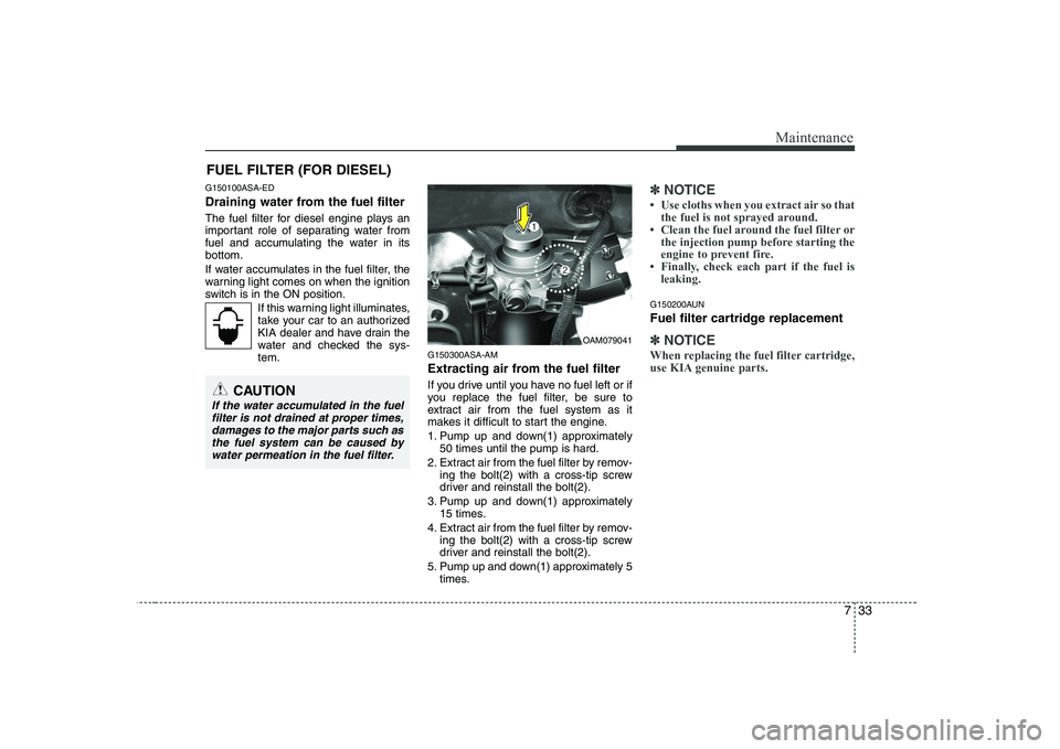
Extracting air from the fuel filter
If you drive until you have no fuel left or if
you replace the fuel filter, be sure to
extract air from the fuel system as it
makes it difficult to start the engine.
1. Pump up and down(1) approximately
50 times until the pump is hard.
2. Extract air from the fuel filter by remov- ing the bolt(2) with a cross-tip screw
driver and reinstall the bolt(2).
3. Pump up and down(1) approximately 15 times.
4. Extract air from the fuel filter by remov- ing the bolt(2) with a cross-tip screw
driver and reinstall the bolt(2).
5. Pump up and down(1) approximately 5 times.
✽✽ NOTICE
Page 297 of 328
Maintenance
56
7
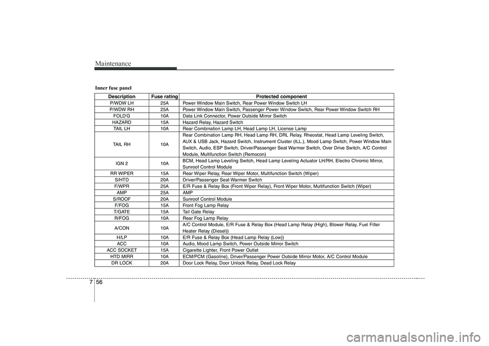
Inner fuse panel
Description Fuse rating Protected component
P/WDW LH 25A Power Window Main Switch, Rear Power Window Switch LH
P/WDW RH 25A Power Window Main Switch, Passenger Power Window Switch, Rear Power Window Switch RH FOLD'G 10A Data Link Connector, Power Outside Mirror Switch
HAZARD 15A Hazard Relay, Hazard Switch TAIL LH 10A Rear Combination Lamp LH, Head Lamp LH, License Lamp
TAIL RH 10A Rear Combination Lamp RH, Head Lamp RH, DRL Relay, Rheostat, Head Lamp Leveling Switch,
AUX & USB Jack, Hazard Switch, Instrument Cluster (ILL.), Mood Lamp Switch, Power Window Main
Switch, Audio, ESP Switch, Driver/Passenger Seat Warmer Switch, Over Drive Switch, A/C Control
Module, Multifunction Switch (Remocon)
IGN 2 10A BCM, Head Lamp Leveling Switch, Head Lamp Leveling Actuator LH/RH, Electro Chromic Mirror,Sunroof Control Module
RR WIPER 15A Rear Wiper Relay, Rear Wiper Motor, Multifunction Switch (Wiper) S/HTD 20A Driver/Passenger Seat Warmer Switch
F/WPR 25A E/R Fuse & Relay Box (Front Wiper Relay), Front Wiper Motor, Multifunction Switch (Wiper) AMP 25A AMP
S/ROOF 20A Sunroof Control Module F/FOG 15A Front Fog Lamp Relay
T/GATE 15A Tail Gate Relay R/FOG 10A Rear Fog Lamp Relay
A/CON 10A A/C Control Module, E/R Fuse & Relay Box (Head Lamp Relay (High), Blower Relay, Fuel Filter
Heater Relay (Diesel))
H/LP 10A E/R Fuse & Relay Box (Head Lamp Relay (Low)) ACC 10A Audio, Mood Lamp Switch, Power Outside Mirror Switch
ACC SOCKET 15A Cigarette Lighter, Front Power Outlet HTD MIRR 10A ECM/PCM (Gasoline), Driver/Passenger Power Outside Mirror Motor, A/C Control ModuleDR LOCK 20A Door Lock Relay, Door Unlock Relay, Dead Lock Relay
Page 298 of 328
757
Maintenance
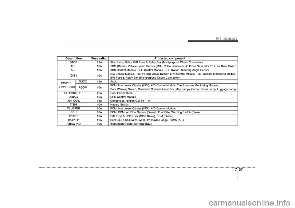
Description Fuse rating Protected componentSTOP 15A Stop Lamp Relay, E/R Fuse & Relay Box (Multipurpose Check Connector)TCU 10A TCM (Diesel), Vehicle Speed Sensor (M/T), Pulse Generator 'A', Pulse Generator 'B', Over Drive SwitchABS 10A ABS Control Module, ESP Control Module, ESP Switch, Steering Angle Sensor
IGN 1 10A A/C Control Module, Rear Parking Assist Buzzer, EPS Control Module, Tire Pressure Monitoring Module,
E/R Fuse & Relay Box (Multipurpose Check Connector)
AUDIO 15A Audio
ROOM 10A BCM, Instrument Cluster (IND.), A/C Control Module, Tire Pressure Monitoring Module,
Door Warning Switch, Overhead Console Assembly (Map Lamp), Center Room Lamp, Luggage Lamp
RR P/OUTLET 15A Rear Power Outlet A/BAG 15A SRS Control Module
IGN COIL 15A Condenser, Ignition Coil #1 ~ #4 T/SIG 10A Hazard Switch
CLUSTER 10A BCM, Instrument Cluster (IND.), A/C Control Module ECU 10A ECM, PCM, Air Flow Sensor (Diesel), Fuel Filter Warning Switch (Diesel)
START 10A E/R Fuse & Relay Box (Start Relay), ECM (Diesel)
B/UP LP 10A Back-up Lamp Switch (M/T), Transaxle Range Switch (A/T)
A/BAG IND 10A Instrument Cluster (Air Bag IND.)
POWER
CONNECTOR
Page 299 of 328
Maintenance
58
7
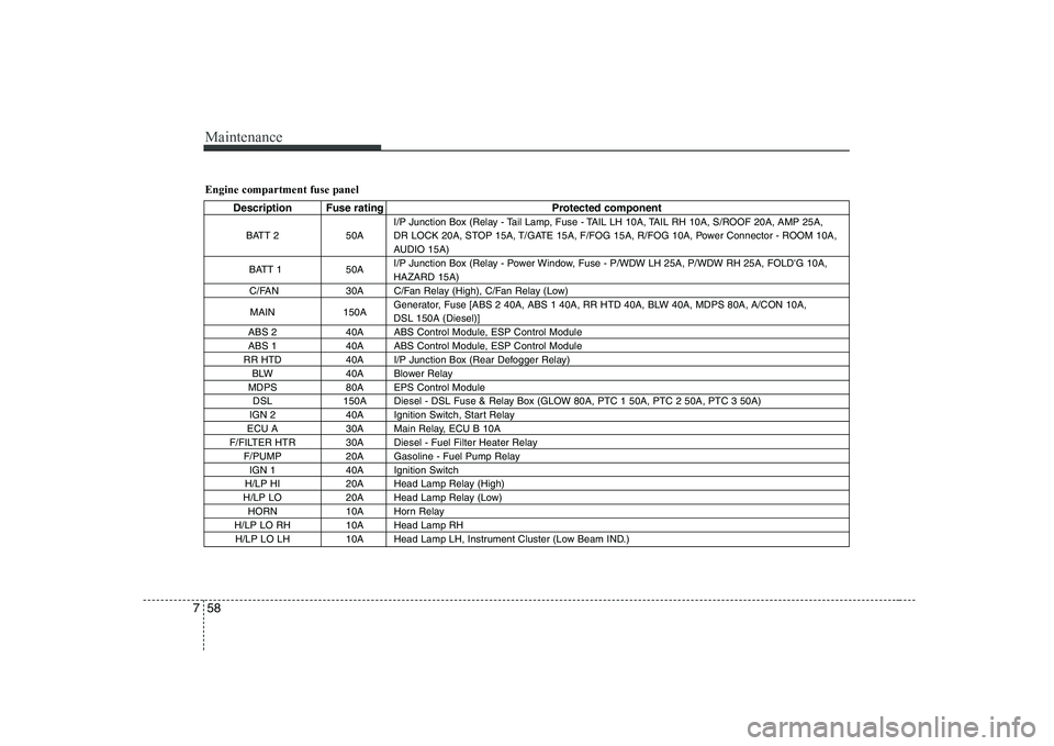
Engine compartment fuse panel
Description Fuse rating Protected component
BATT 2 50A I/P Junction Box (Relay - Tail Lamp, Fuse - TAIL LH 10A, TAIL RH 10A, S/ROOF 20A, AMP 25A,
DR LOCK 20A, STOP 15A, T/GATE 15A, F/FOG 15A, R/FOG 10A, Power Connector - ROOM 10A,
AUDIO 15A)
BATT 1 50A I/P Junction Box (Relay - Power Window, Fuse - P/WDW LH 25A, P/WDW RH 25A, FOLD'G 10A,HAZARD 15A)
C/FAN 30A C/Fan Relay (High), C/Fan Relay (Low)
MAIN 150A Generator, Fuse [ABS 2 40A, ABS 1 40A, RR HTD 40A, BLW 40A, MDPS 80A, A/CON 10A, DSL 150A (Diesel)]
ABS 2 40A ABS Control Module, ESP Control Module
ABS 1 40A ABS Control Module, ESP Control Module
RR HTD 40A I/P Junction Box (Rear Defogger Relay) BLW 40A Blower Relay
MDPS 80A EPS Control Module DSL 150A Diesel - DSL Fuse & Relay Box (GLOW 80A, PTC 1 50A, PTC 2 50A, PTC 3 50A)
IGN 2 40A Ignition Switch, Start Relay
ECU A 30A Main Relay, ECU B 10A
F/FILTER HTR 30A Diesel - Fuel Filter Heater Relay F/PUMP 20A Gasoline - Fuel Pump RelayIGN 1 40A Ignition Switch
H/LP HI 20A Head Lamp Relay (High)
H/LP LO 20A Head Lamp Relay (Low) HORN 10A Horn Relay
H/LP LO RH 10A Head Lamp RH H/LP LO LH 10A Head Lamp LH, Instrument Cluster (Low Beam IND.)
Page 315 of 328
Maintenance
74
7
EMISSION CONTROL SYSTEM
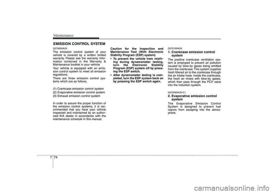
G270000AUN
The emission control system of your
vehicle is covered by a written limited
warranty. Please see the warranty infor-
mation contained in the Warranty &
Maintenance booklet in your vehicle.
Your vehicle is equipped with an emis- sion control system to meet all emission
regulations. There are three emission control sys-
tems which are as follows.
(1) Crankcase emission control system
(2) Evaporative emission control system(3) Exhaust emission control system In order to assure the proper function of
the emission control systems, it is rec-
ommended that you have your vehicle
inspected and maintained by an author-
ized KIA dealer in accordance with the
maintenance schedule in this manual. Caution for the Inspection and
Maintenance Test (With Electronic
Stability Program (ESP) system)
To prevent the vehicle from misfir-
ing during dynamometer testing,
turn the Electronic Stability
Program (ESP) system off by press-
ing the ESP switch.
After dynamometer testing is com- pleted, turn the ESP system back on
by pressing the ESP switch again. G270100AUN
1. Crankcase emission control
system
The positive crankcase ventilation sys-
tem is employed to prevent air pollution
caused by blow-by gases being emitted
from the crankcase. This system supplies
fresh filtered air to the crankcase through
the air intake hose. Inside the crankcase,
the fresh air mixes with blow-by gases,
which then pass through the PCV valveinto the induction system.
G270200AUN-C1
2. Evaporative emission control system
The Evaporative Emission Control
System is designed to prevent fuel
vapors from escaping into the atmos-
phere.
Page 321 of 328
Specifications & Consumer information
4
8
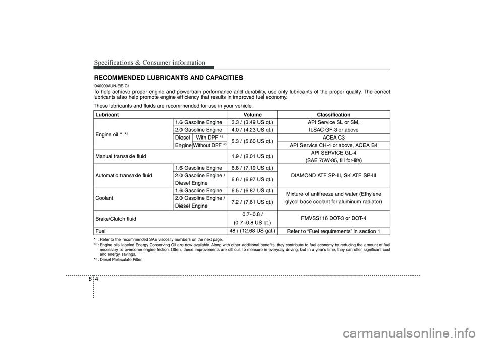
RECOMMENDED LUBRICANTS AND CAPACITIES
I040000AUN-EE-C1
To help achieve proper engine and powertrain performance and durability, use only lubricants of the proper quality. The correct
lubricants also help promote engine efficiency that results in improved fuel economy.
These lubricants and fluids are recommended for use in your vehicle.
* 1
: Refer to the recommended SAE viscosity numbers on the next page.
* 2
: Engine oils labeled Energy Conserving Oil are now available. Along with other additional benefits, they contribute to fuel economy by reducing the amount of fuel
necessary to overcome engine friction. Often, these improvements are difficult to measure in everyday driving, but in a year’s time, they can offer significant cost
and energy savings.
* 3
: Diesel Particulate Filter
Lubricant Volume Classification
1.6 Gasoline Engine 3.3 l(3.49 US qt.) API Service SL or SM,
2.0 Gasoline Engine 4.0 l(4.23 US qt.) ILSAC GF-3 or above
Engine oil * 1
*2
Diesel With DPF *3
5.3 l(5.60 US qt.) ACEA C3
Engine Without DPF * 3
API Service CH-4 or above, ACEA B4
Manual transaxle fluid 1.9 l(2.01 US qt.) API SERVICE GL-4
(SAE 75W-85, fill for-life)
1.6 Gasoline Engine 6.8 l(7.19 US qt.)
Automatic transaxle fluid 2.0 Gasoline Engine / 6.6 l(6.97 US qt.) DIAMOND ATF SP-III, SK ATF SP-III
Diesel Engine
1.6 Gasoline Engine 6.5 l(6.87 US qt.)
Mixture of antifreeze and water (Ethylene
Coolant 2.0 Gasoline Engine / 7.2 l(7.61 US qt.)
Diesel Engine glycol base coolant for aluminum radiator)
Brake/Clutch fluid 0.7~0.8
l
FMVSS116 DOT-3 or DOT-4
(0.7~0.8 US qt.)
Fuel 48
l(12.68 US gal.)
Refer to “Fuel requirements” in section 1