Page 86 of 521
can be adjusted either from the radio volume control
knob or from the steering wheel radio control (right
switch), if so equipped.
The radio display will be used for visual prompts from
the uconnect�phone such as�CELL�or caller ID on
certain radios.
Operation
Voice commands can be used to operate the uconnect�
phone and to navigate through the uconnect�phone
menu structure. Voice commands are required after most
uconnect�phone prompts. You will be prompted for a
specific command and then guided through the available
options.
•Prior to giving a voice command, one must wait for
the beep, which follows the�Ready�prompt or another
prompt.
•For certain operations, compound commands can be
used. For example, instead of saying�Setup�and then
�Phone Pairing,�the following compound command
can be said:�Setup Phone Pairing.�
•For each feature explanation in this section, only the
combined form of the voice command is given. You
can also break the commands into parts and say each
part of the command when you are asked for it. For
example, you can use the combined form voice com-
mand�Phonebook New Entry,�or you can break the
combined form command into two voice commands:
�Phonebook�and�New Entry.�Please remember, the
uconnect�phone works best when you talk in a
normal conversational tone, as if speaking to someone
sitting a few feet/meters away from you.
Voice Command Tree
Refer to “Voice Tree” in this section.
84 UNDERSTANDING THE FEATURES OF YOUR VEHICLE
Page 132 of 521
WARNING!
If the hood is not fully latched, it could fly up when
the vehicle is moving and block your forward vision.
Be sure all hood latches are fully latched before
driving.
LIGHTS
Multifunction Lever
The multifunction lever controls the operation of the
headlights, turn signals, headlight beam selection, instru-
ment panel light dimming, passing light, interior
courtesy/dome lights, and optional fog lights. The mul-
tifunction lever is located on the left side of the steering
wheel.
Headlights and Parking Lights
Turn the end of the multifunction lever to the first detent
for parking light operation. Turn to the second detent for
headlight operation. Turn to the third detent for AUTO
headlight operation (if equipped).
Headlight Switch
130 UNDERSTANDING THE FEATURES OF YOUR VEHICLE
Page 139 of 521
High Beam Switch
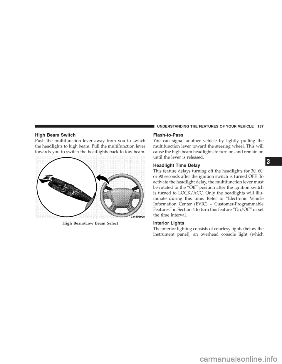
Push the multifunction lever away from you to switch
the headlights to high beam. Pull the multifunction lever
towards you to switch the headlights back to low beam.
Flash-to-Pass
You can signal another vehicle by lightly pulling the
multifunction lever toward the steering wheel. This will
cause the high beam headlights to turn on, and remain on
until the lever is released.
Headlight Time Delay
This feature delays turning off the headlights for 30, 60,
or 90 seconds after the ignition switch is turned OFF. To
activate the headlight delay, the multifunction lever must
be rotated to the “Off” position after the ignition switch
is turned to LOCK/ACC. Only the headlights will illu-
minate during this time. Refer to “Electronic Vehicle
Information Center (EVIC) – Customer-Programmable
Features” in Section 4 to turn this feature “On/Off” or set
the time interval.
Interior Lights
The interior lighting consists of courtesy lights (below the
instrument panel), an overhead console light (which
High Beam/Low Beam Select
UNDERSTANDING THE FEATURES OF YOUR VEHICLE 137
3
Page 144 of 521
operate until the wiper switch is moved, vehicle speed
is greater than 0 mph (0 km/h), or the outside tem-
perature is greater than 32°F (0°C).
•Transmission in NEUTRAL Position— When the
ignition is ON, and the transmission is in the NEU-
TRAL position, the rain sensing system will not oper-
ate until the wiper switch is moved, vehicle speed is
greater than 5 mph (8 km/h), or the shift lever is
moved out of the NEUTRAL position.
TILT/TELESCOPING STEERING COLUMN
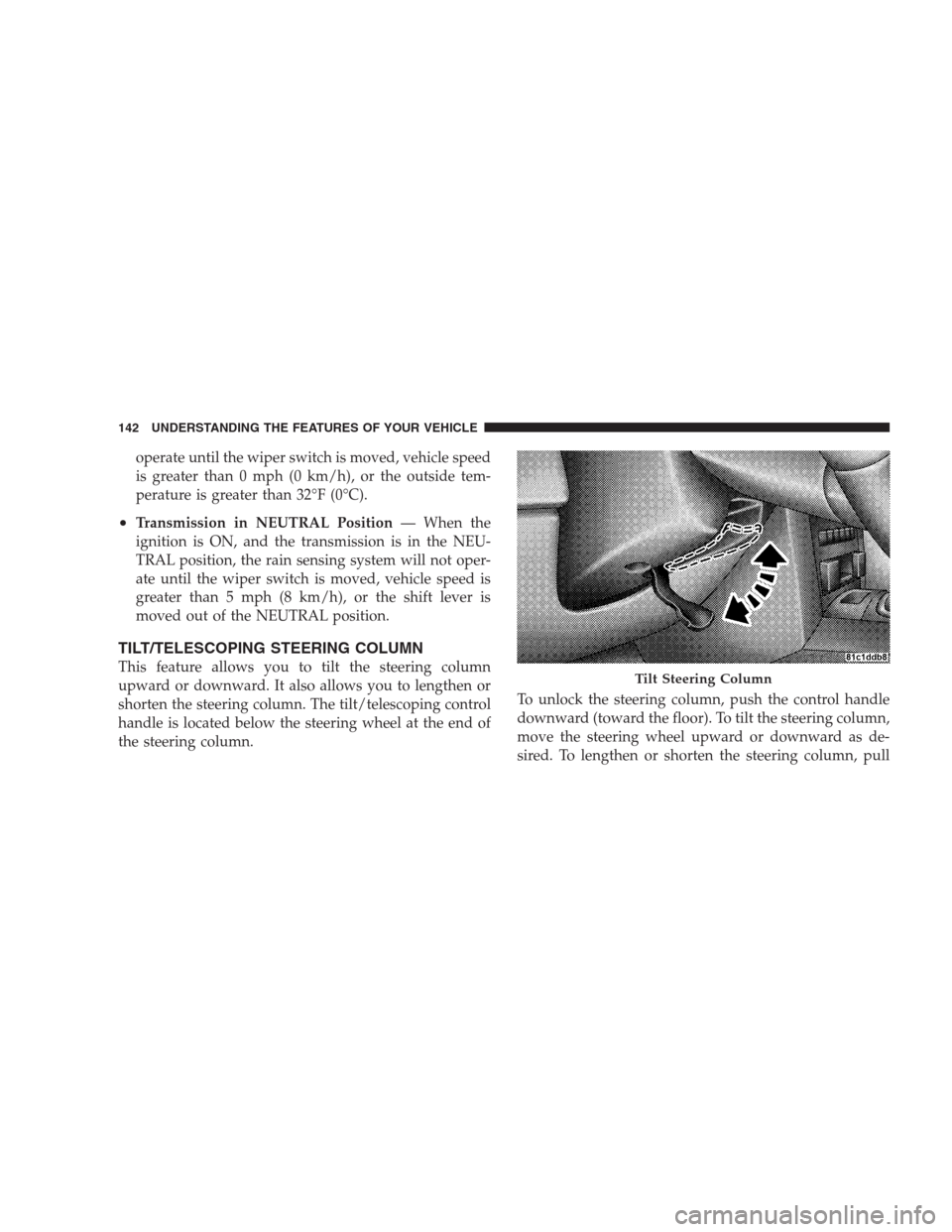
This feature allows you to tilt the steering column
upward or downward. It also allows you to lengthen or
shorten the steering column. The tilt/telescoping control
handle is located below the steering wheel at the end of
the steering column.To unlock the steering column, push the control handle
downward (toward the floor). To tilt the steering column,
move the steering wheel upward or downward as de-
sired. To lengthen or shorten the steering column, pullTilt Steering Column
142 UNDERSTANDING THE FEATURES OF YOUR VEHICLE
Page 145 of 521
the steering wheel outward or push it inward as desired.
To lock the steering column in position, push the control
handle upward until fully engaged.
WARNING!
Do not adjust the steering wheel while driving. The
telescoping adjustment must be locked while driv-
ing. Adjusting the steering wheel while driving or
driving without the telescoping adjustment locked
could cause the driver to lose control of the vehicle.
ADJUSTABLE PEDALS — IF EQUIPPED
This feature allows both the brake and accelerator pedals
to move toward or away from the driver to provide
improved position with the steering wheel. The adjust-
able pedal system is designed to allow a greater range of
driver comfort for steering wheel tilt and seat position.
The position of the brake and accelerator pedals can beadjusted without compromising safety or comfort in
actuating the pedals.
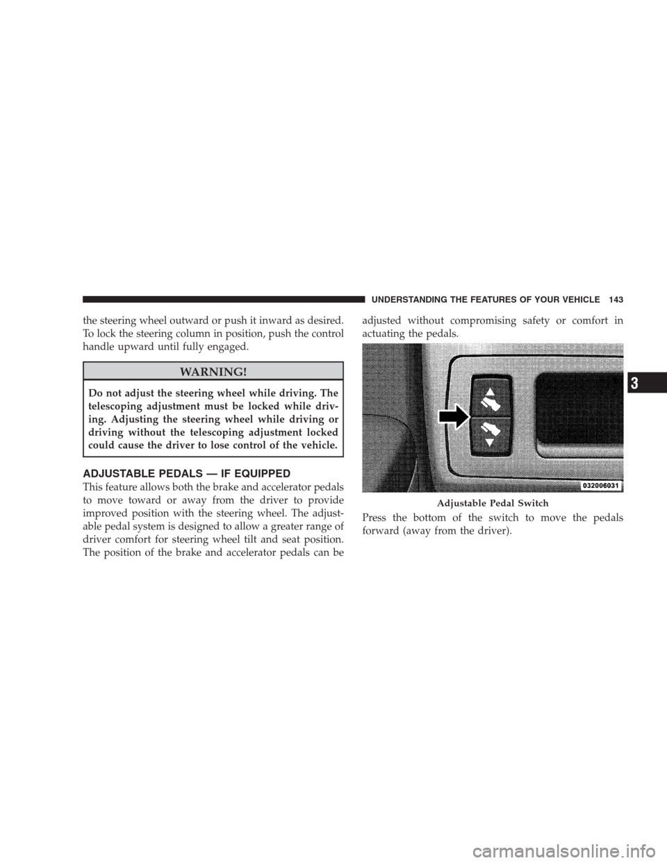
Press the bottom of the switch to move the pedals
forward (away from the driver).
Adjustable Pedal Switch
UNDERSTANDING THE FEATURES OF YOUR VEHICLE 143
3
Page 146 of 521
Press the top of the switch to move the pedals rearward
(toward the driver).
•The pedals can be adjusted with the ignition OFF.
•The pedals can be adjusted while driving.
•The pedalscannotbe adjusted when the vehicle is in
REVERSE (R) or when the Electronic Speed Control is
ON. A message will be displayed in the Electronic
Vehicle Information Center (EVIC) if the pedals are
attempted to be adjusted when the system is locked
out (“Adjustable Pedal Disabled — Cruise Control
Engaged” or “Adjustable Pedal Disabled — Vehicle In
Reverse”). Refer to Electronic Vehicle Information
Center (EVIC) in Section 4 for more information.
CAUTION!
Do not place any article under the adjustable pedal’s
or impede its ability to move as it may cause damage
to the pedal controls. Pedal travel may become lim-
ited if movement is stopped by an obstruction in the
adjustable pedal’s path.
ELECTRONIC SPEED CONTROL — IF EQUIPPED
When engaged, Electronic Speed Control takes over
accelerator operations at speeds greater than 25 mph
(40 km/h) for 3.7L, 4.7L, and 5.7L engines; and 14 mph
(23 km/h) for 3.0L diesel engines.
The Electronic Speed Control lever is located on the right
side of the steering wheel.
144 UNDERSTANDING THE FEATURES OF YOUR VEHICLE
Page 174 of 521
The cargo load floor is held by spring loaded latches. In
order to use the cargo load floor, use the following
procedure:
NOTE: The cargo load floor latches should not be
used as cargo tie-downs.
1. Flip up pull loop(s) so they are perpendicular (straight
up) to the top surface of the tray.
2. Pull up on loop(s) and twist 90 degrees, so they are
parallel to the slotted hole in tray.
3. Lift the tray over the loop(s), and reposition the tray.
4. Pull up on the loop(s) and twist 90 degrees, so they are
perpendicular (straight up) to the slotted hole in tray.
5. Push the loop(s) back down, so they are parallel to the
top of the tray.REAR WINDOW FEATURES
Rear Window Wiper/Washer
A switch on the right side of the steering column controls
operation of the rear wiper/washer function. Rotating
the center of the switch forward to the on position will
activate the wiper. The rear wiper operates in an inter-
mittent mode only. Rotating the center of the switch all
the way forward will turn on the wash function. The
wash pump will continue to operate as long as the button
is pressed. Upon release, the wipers will cycle two times
before returning to the set position.
172 UNDERSTANDING THE FEATURES OF YOUR VEHICLE
Page 196 of 521
•Vehicle Information Warning Message Displays
•Personal Settings (Customer-Programmable Features)
•Compass Display
•Outside Temperature Display
•Trip Computer Functions
The system allows the driver to select information by
pressing the following buttons mounted on the steering
wheel:
MENU Button
Press and release the MENU button and the
mode displayed will change between Trip
Functions, Personal Settings, and System Sta-
tus.FUNCTION SELECT Button
Press the FUNCTION SELECT button to select
the displayed function YES (Y) or NO (N).
SCROLL Button
Press the SCROLL button to scroll through Trip
Functions, Personal Settings (Customer Pro-
grammable Features), and System Status Mes-
sages.
COMPASS/TEMPERATURE Button
Press and release the COMPASS/
TEMPERATURE button to display one of eight
compass readings and the outside temperature.
194 UNDERSTANDING YOUR INSTRUMENT PANEL