Page 75 of 391

75
Lighting
LIGHTING CONTROL
Note: If the ignition system is switched off and
the lamps are left on, the message centre will
display LIGHTS ON.
The exterior lamps are controlled by the
left-hand column stalk switch.
The rotary collar on the stalk has three
positions for turning the exterior lamps on or
off and positions for auto lamps and exit delay.
Off
All exterior lamps off (except vehicles provided
with daylight running lamps).
Side lamps
Switches on the side lamps, tail, number plate
and any other marker lamps required by local
legislation. The instrument panel will also be lit.
Headlamps
Select this positi on to switch on the
headlamps. Headlamp flash:
Pull the switch towards the
steering wheel and release to flash the high
beam on and off. The high beam will remain on
for as long as the switch is held.
High beam: With the headlamps on, push the
switch away from the steering wheel to switch
to high beam.
The blue warning indicator on the instrument
panel will illuminate.
To turn high beam off and return to low beam,
pull the column switch towards the steering
wheel.
Note: If the rotary control switch is moved to
the OFF position, with hi gh beam still activated,
both low and high beam will be extinguished.
Both low and high beam will illuminate when
the headlamps are turned on again.
E91137
E91138
E91139
E91140
E91141
Page 77 of 391

77
Lighting
Exit delay
Three settings on the rotary collar set the time
that the headlamps will remain on after the
driver’s door has closed:
1.30 seconds.
2. 60 seconds.
3. 120 seconds.
The message centre displays the selected delay
time (e.g. AUTOLAMP DELAY 0:60 ) or displays
AUTOLAMP DELAY OFF when the autolamp
delay function has been turned off.
Note: If the lamp switch ro tary collar is in the
AUTO position there will be no exit delay and
the headlamps will extinguish when the ignition
system is turned off.
REAR FOG LAMPS
Rear fog lamps will only operate when
headlamp dipped beam or Auto lamps are
selected. Press the rear fog lamp button to
switch on, press again to switch off.
HAZARD WARNING FLASHERS
Press the switch to turn the hazard warning
lamps on. When the hazard warning lamps are
operating, the indicator warning lamps will
flash in time with the hazard warning lamps.
Press again to turn the lamps off.
Use only in an emergency, to warn traffic of a
vehicle breakdown or approaching danger.
Note: Hazard warning lamps can be used when
the ignition is on or off.
JAG0924
1
2
3
JAG1332
E94710
Page 78 of 391

Lighting
78
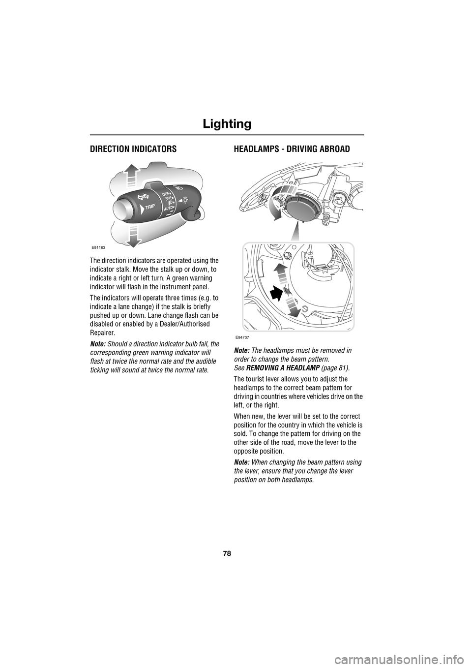
DIRECTION INDICATORS
The direction indicators are operated using the
indicator stalk. Move the stalk up or down, to
indicate a right or left turn. A green warning
indicator will flash in the instrument panel.
The indicators will operate three times (e.g. to
indicate a lane change) if the stalk is briefly
pushed up or down. Lane change flash can be
disabled or enabled by a Dealer/Authorised
Repairer.
Note: Should a direction indicator bulb fail, the
corresponding green warning indicator will
flash at twice the normal rate and the audible
ticking will sound at twice the normal rate.
HEADLAMPS - DRIVING ABROAD
Note: The headlamps must be removed in
order to change the beam pattern.
See REMOVING A HEADLAMP (page 81).
The tourist lever allows you to adjust the
headlamps to the correct beam pattern for
driving in countries wher e vehicles drive on the
left, or the right.
When new, the lever will be set to the correct
position for the country in which the vehicle is
sold. To change the pattern for driving on the
other side of the road, move the lever to the
opposite position.
Note: When changing the beam pattern using
the lever, ensure that you change the lever
position on both headlamps.
E91163
E94707
Page 79 of 391

79
Lighting
HEADLAMP LEVELLING
Halogen headlamps
Use the headlamp levelling control to account
for vehicle loading changes.
Xenon headlamps
Headlamp levelling is adjusted automatically if
Xenon headlamps are fitted, to account for
vehicle load conditions, to avoid dazzling
oncoming drivers.
CORNERING OR STATIC BENDING
LAMPS
Cornering or static bending lamps are angled
outwards from the centre line of the vehicle.
These lamps broaden the beam of the
headlamps when cornering during normal
night driving.
1. Light spread of a vehicle not fitted with
static bending lamps.
2. Light spread of a vehicle fitted with static
bending lamps
The system switches on the lamp if it has
received an input from the vehicle's direction
indicator. Only the lamp on the same side as
the operating direction indicator illuminates.
The system only operate s with the ignition
switched on.
Vehicle load Switch position
Driver only 0
Driver and front seat
passenger
1
Driver and pa ssengers in
all seats 2
Maximum gross vehicle
weight 2
Maximum rear axle load 2 or 3
JAG1334
1
2
JAG0923
Page 81 of 391

81
Lighting
Note: For lamps controlled by proximity
sensors, the wearing of gloves may interfere
with operation. If you are wearing gloves, it
may be necessary to touch the proximity
switch to operate the lamps.
Ambience lighting
Ambience lighting. Automatically illuminates
when the headlamps are on. Ambience lighting
creates a blue glow ar ound the centre console
and front door armrests.
Luggage compartment lamp
Automatically illuminates when the luggage
compartment is opened.
APPROACH LAMPS
This feature is activated by pressing
the headlamp icon button on the
Jaguar Smart Key. See USING THE
REMOTE CONTROL (page 17). The headlamps
will remain on for 25 seconds or until the
button is pressed again, or until the engine
START/STOP button is pressed.
REMOVING A HEADLAMP
1. Open the bonnet. See OPENING AND
CLOSING THE BONNET (page 195).
2. Remove the two bolts from the top of the
headlamp unit.
3. Remove the retaining bolt located in the
wheel arch.
Note: To improve access to the wheel arch,
turn the steering wheel to full lock, in the
direction of the affected headlamp.
4. Pull the headlamp away slightly from the
body of the vehicle.CAUTION
It is recommended that the following
procedure should only be attempted by
a qualified technician. If in doubt, consult your
Dealer/Authorised Repairer.
Do not place the removed lamp unit face
down on hard or abrasive surfaces.
Doing so may scratch the surface of the lens.
3
2
2
E94719
2
4
Page 82 of 391
Lighting
82
5.Press the tab and pull to disconnect the
electrical connector.
6. Press the clip and pull to disconnect the
headlamp washer hose (if headlamp
washers are fitted).
7. Remove the headlamp unit.
REMOVING A REAR LAMP
Only the rear directio n indicator and reverse
lamp bulbs can be repl aced. Failure of any
other rear lamp unit should be investigated by
a qualified technician. Consult your Dealer/
Authorised Repairer.
Note: Access to the rear lamp units is achieved
through access hatche s, located behind the
rear boot trim.
1. Remove the two retaining nuts.
2. Pull and slide the lamp unit rearwards to
remove.
CAUTION
It is recommended that the following
procedure should only be attempted by
a qualified technician. If in doubt, consult your
Dealer/Authorised Repairer.
Do not place the removed lamp unit face
down on hard or abrasive surfaces.
Doing so may scratch the surface of the lens.
E94720
5
6
E94721
Page 83 of 391

83
Lighting
CHANGING A BULB
General information
Note: In certain markets its a legal requirement
to carry spare bulbs. A replacement bulb kit is
available as an approved accessory from your
Dealer/Authorised Repairer.
Halogen bulbs
Halogen bulbs are used for main beam and
dipped beam headlamps. Take care not to
touch the glass part of the bulb with your
fingers; always use a cl oth to handle the bulb.
If necessary use methylated spirits to remove
finger prints.
Xenon lamps
Seek advice about the correct
disposal of Xenon lamp units from
your Dealer/Authorised Repairer, or
your local authority.
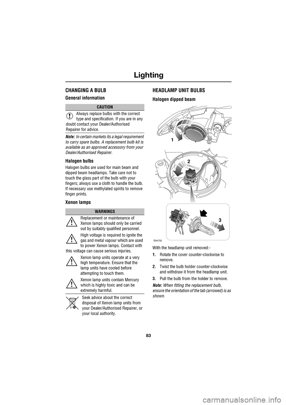
HEADLAMP UNIT BULBS
Halogen dipped beam
With the headlamp unit removed:-
1. Rotate the cover counter-clockwise to
remove.
2. Twist the bulb holder counter-clockwise
and withdraw it from the headlamp unit.
3. Pull the bulb from the holder to remove.
Note: When fitting the replacement bulb,
ensure the orientation of the tab (arrowed) is as
shown.
CAUTION
Always replace bulbs with the correct
type and specification. If you are in any
doubt contact your Dealer/Authorised
Repairer for advice.
WARNINGS
Replacement or maintenance of
Xenon lamps should only be carried
out by suitably qualified personnel.
High voltage is required to ignite the
gas and metal vapour which are used
to power Xenon lamps. Contact with
this voltage can cause serious injuries.
Xenon lamp units operate at a very
high temperature. Ensure that the
lamp units have cooled before
attempting to touch them.
Xenon lamp units contain Mercury
which is highly toxic and can be
extremely harmful.
E94732
1
2
3
Page 84 of 391
Lighting
84
Halogen dipped and main beam
With the headlamp unit removed:-
1.Rotate the relevant cover
counter-clockwise to remove.
2. Twist the bulb holder counter-clockwise
and withdraw it from the headlamp unit.
3. Pull the bulb from the holder to remove.
Note: When fitting the replacement bulb,
ensure the orientation of the tab (arrowed) is as
shown.
Direction indicator bulbs
With the headlamp unit removed:-
1. Twist the indicator bulb holder
counter-clockwise, and remove it from the
lamp unit.
2. Press the bulb into the holder, then twist it
to remove.
E94733
1
2
3
E94734
1
2