2009 JAGUAR XF Rear seat
[x] Cancel search: Rear seatPage 79 of 391

79
Lighting
HEADLAMP LEVELLING
Halogen headlamps
Use the headlamp levelling control to account
for vehicle loading changes.
Xenon headlamps
Headlamp levelling is adjusted automatically if
Xenon headlamps are fitted, to account for
vehicle load conditions, to avoid dazzling
oncoming drivers.
CORNERING OR STATIC BENDING
LAMPS
Cornering or static bending lamps are angled
outwards from the centre line of the vehicle.
These lamps broaden the beam of the
headlamps when cornering during normal
night driving.
1. Light spread of a vehicle not fitted with
static bending lamps.
2. Light spread of a vehicle fitted with static
bending lamps
The system switches on the lamp if it has
received an input from the vehicle's direction
indicator. Only the lamp on the same side as
the operating direction indicator illuminates.
The system only operate s with the ignition
switched on.
Vehicle load Switch position
Driver only 0
Driver and front seat
passenger
1
Driver and pa ssengers in
all seats 2
Maximum gross vehicle
weight 2
Maximum rear axle load 2 or 3
JAG1334
1
2
JAG0923
Page 94 of 391

Windows and mirrors
94
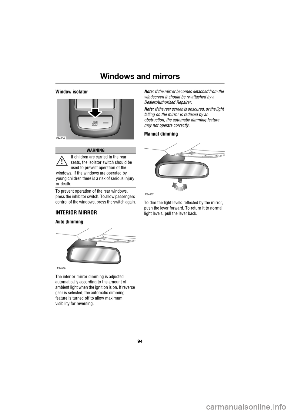
Window isolator
To prevent operation of the rear windows,
press the inhibitor switch. To allow passengers
control of the windows, press the switch again.
INTERIOR MIRROR
Auto dimming
The interior mirror dimming is adjusted
automatically according to the amount of
ambient light when the i gnition is on. If reverse
gear is selected, the automatic dimming
feature is turned off to allow maximum
visibility for reversing. Note:
If the mirror becomes detached from the
windscreen it should be re-attached by a
Dealer/Authorised Repairer.
Note: If the rear screen is obscured, or the light
falling on the mirror is reduced by an
obstruction, the automa tic dimming feature
may not operate correctly.
Manual dimming
To dim the light levels re flected by the mirror,
push the lever forward. To return it to normal
light levels, pull the lever back.
WARNING
If children are carried in the rear
seats, the is olator switch should be
used to prevent operation of the
windows. If the windows are operated by
young children there is a risk of serious injury
or death.
E94756
E94836
E94837
Page 100 of 391

Instruments
100
WARNING LAMPS AND INDICATORS
1.Anti-lock Braking System (ABS)/
Electronic Parking Brake (EPB).
2. Adaptive Cruise Control (ACC).
3. Glow plugs (diesel only).
4. Adaptive front lighting system (AFL).
5. Engine malfunction.
6. Tyre Pressure M onitoring System
(TPMS).
7. Airbag.
8. Right-hand direct ion indicator.
9. Rear fog lamp.
10. Dynamic Stability Control (DSC).
11. High beam.
12. Side lamps.
13. Seat belt.
14. Message centre.
15. Automatic Speed Limiter (ASL).
16. Forward alert.
17. Brakes - Electric Parking Brake (EPB)
On/Brake fluid low/El ectronic Brakeforce
Distribution (EBD)
18. Left-hand direction indicator. RED
warning indicators are for primary
warnings. A primary warning must be
investigated immediately by the driver or seek
qualified assistance as soon as possible.
AMBER warning indicators are for secondary
warnings, to indicate that a vehicle system is in
operation or that the driver must take action
and then seek qualified assistance.
Other indicators within the instrument panel
indicate system status (e .g. blue for main beam
or green for direction indicators, when in use).
Indicator check
An indicator bulb check is initiated when the
ignition system is switched on and lasts for
three seconds (excepting the airbag warning
indicator which will remain on for six seconds).
If any warning indicator remains on after this
period, investigate the cause before driving.
Some warning indicators have associated
messages displayed on the message centre.
Note: Not all warning indicators are included in
the check (e.g. main beam headlamps and
direction indicators).
Akm
l/100km
JAG1631
123456
789101817161514131211
Page 115 of 391

115
Climate control
AIR VENTS
1.Air volume adjust.
2. Air direction adjust.
3. Solar sensor.
The rotating air vents acti vate and rotate out of
the fascia when the engine START/STOP
button is pressed, provided the climate system
has not been manually switched off. Adjust the
volume of air usi ng the thumbwheels ( 1) and
the direction of the air using the direction
controls ( 2), to suit your requirements.
It is possible to set the air vents so that they
remain permanently on view, even when the
ignition is switched off. From the touch-screen Climate menu, select
Settings
. Select Vent rotation Always open .
Rear vents
The temperature of the air supplied by the rear
air vents is dependent on the combined
temperature settings for the driver and front
passenger. For example, if the driver
temperature is set to 21°C (70°F) and 20°C
(68°F) for the front passenger, the temperature
of the air supplied to the rear of the vehicle will
be approximately 20.5°C (69°F).
AkI t F1 k
E95077
11
1
23
2
1
2
2
CAUTIONS
Do not obstruct the solar sensor ( 3) or
the temperature a nd humidity sensor,
located adjacent to the glove box.
Do not obstruct the extract vents for the
climate system, located in the trim panel
behind the rear seats.
Climate
SensitivityAuto
Climate seat settings
Vent rotation
12 : 26 pm
Auto Always
open
Change units External 15˚c
Left Right
Auto
E95447
Page 126 of 391

Convenience features
126
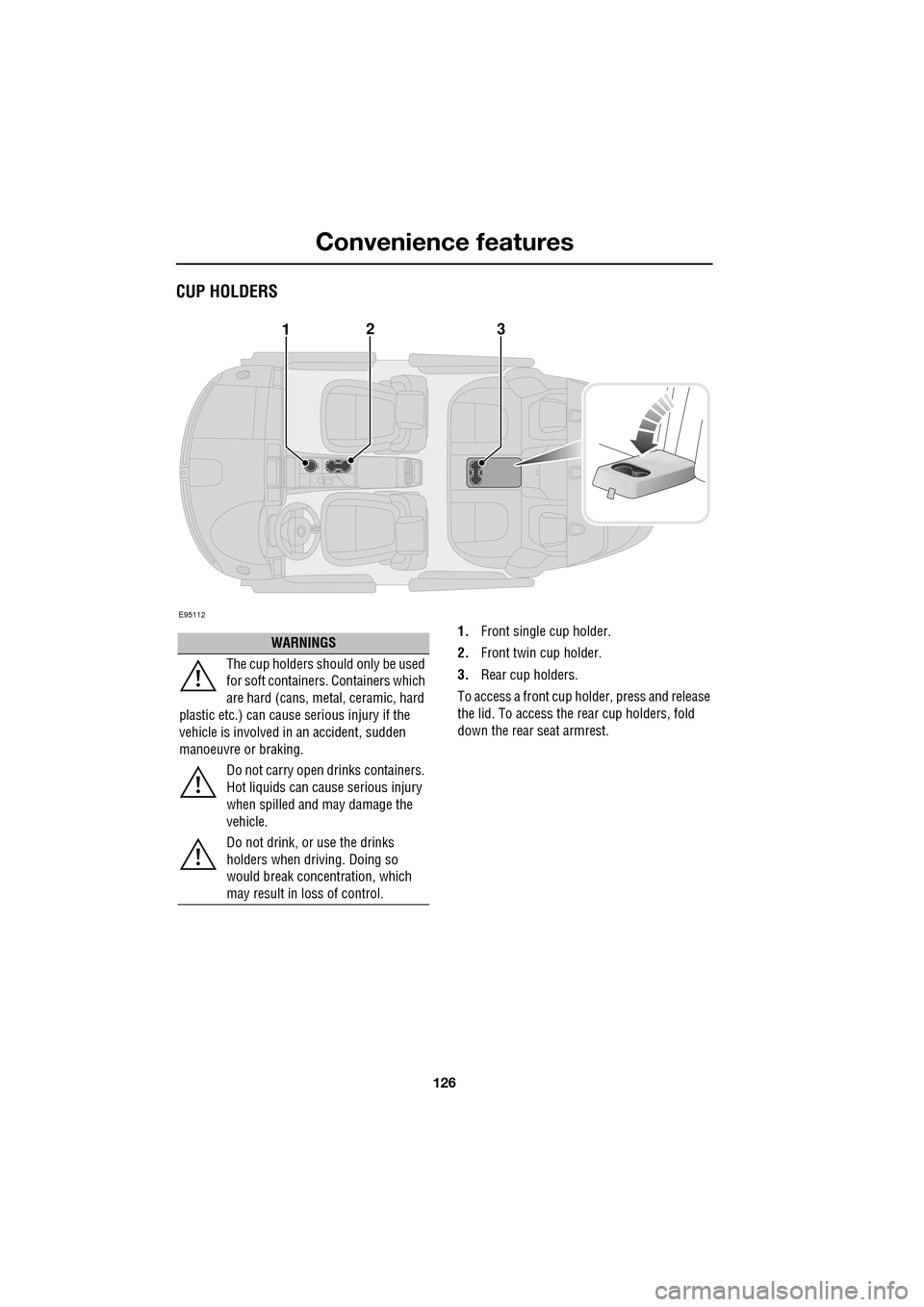
CUP HOLDERS
1.Front single cup holder.
2. Front twin cup holder.
3. Rear cup holders.
To access a front cup holder, press and release
the lid. To access the re ar cup holders, fold
down the rear seat armrest.
E95112
123
WARNINGS
The cup holders shoul d only be used
for soft containers . Containers which
are hard (cans, metal, ceramic, hard
plastic etc.) can cause serious injury if the
vehicle is involved in an accident, sudden
manoeuvre or braking.
Do not carry open drinks containers.
Hot liquids can cause serious injury
when spilled and may damage the
vehicle.
Do not drink, or use the drinks
holders when driving. Doing so
would break concentration, which
may result in loss of control.
Page 127 of 391

127
Convenience features
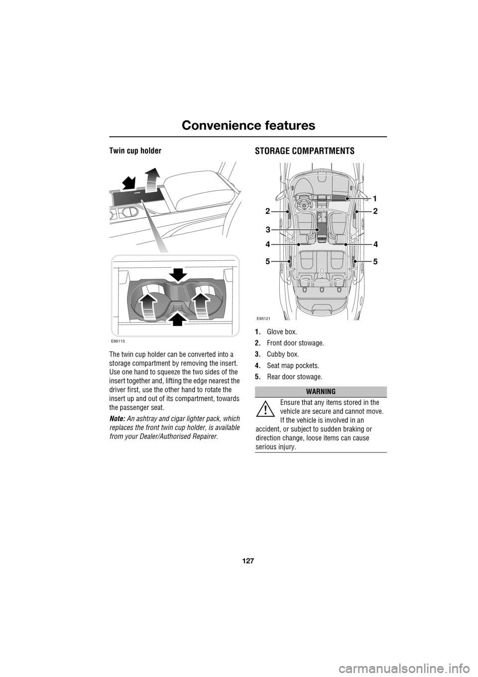
Twin cup holder
The twin cup holder can be converted into a
storage compartment by removing the insert.
Use one hand to squeeze the two sides of the
insert together and, lifting the edge nearest the
driver first, use the other hand to rotate the
insert up and out of it s compartment, towards
the passenger seat.
Note: An ashtray and cigar lighter pack, which
replaces the front twin cup holder, is available
from your Dealer/A uthorised Repairer.
STORAGE COMPARTMENTS
1.Glove box.
2. Front door stowage.
3. Cubby box.
4. Seat map pockets.
5. Rear door stowage.
E95113
WARNING
Ensure that any items stored in the
vehicle are secure and cannot move.
If the vehicle is involved in an
accident, or subject to sudden braking or
direction change, loose items can cause
serious injury.
E95121
22
3
44
5
1
5
Page 145 of 391

145
Brakes
During emergency braking conditions ABS
constantly monitors the speed of each wheel.
ABS varies the brake pressure to individual
wheels, according to the grip available. The
constant alteration of brake pressure can be
felt as a pulsing sensation through the brake
pedal. This is not a caus e for concern, as it is
designed to demonstrate to the driver that ABS
is operating.
ABS braking techniques
For optimum ABS performance, these
instructions on braking techniques during ABS
operation should be followed:
• Do not release the brake pressure when
the pulsating effect is felt. Maintain a
constant pressure until the manoeuvre is
completed.
• To familiarise y ourself with the feel of the
brake pedal during ABS braking, practise
an emergency stop pr ocedure, always
making sure it is safe to do so. With the
seat belts fitted to all occupants, drive the
vehicle at 32 km/h (20 mph) and brake
sharply.
• ABS enables the driver to steer around
obstacles during em ergency braking.
However, the consequences of turning
sharply at high speed cannot be overcome
by the ABS.
• Do not attempt to pump the brakes to
avoid skidding, as this can interfere with
ABS operation. The ABS will not allow the
wheels to skid under normal road
conditions.
• The ABS will tend to keep the vehicle
straight during braki ng. Because braking
distances may increase under certain road
conditions, it is nece ssary to plan and
make turning manoeuvres as early as
possible.
Electronic Brakeforce Distribution (EBD)
EBD balances the distribution of braking forces
between the wheels on the front and rear axles,
to maintain maximum braking under all vehicle
loading conditions.
For example; Under light loads, EBD applies
less braking effort to the rear wheels, to
maintain stability. Conv ersely, it allows full
braking effort to the rear wheels when the
vehicle is towing or is heavily laden.
A fault with the EBD system is
indicated by illumination of the red
brake warning indicator and the
message EBD FAULT is displayed in the
message centre. Gently stop the vehicle, as
soon as safety permit s, and seek qualified
assistance.
Page 185 of 391

185
Towing
RECOMMENDED TOWING WEIGHTS
Nose/tongue weight must be the greater of
50 kg (110 lbs) or 7% of the actual trailer
weight, up to the maximum tow hitch load.
Nose/tongue weight can be measured using a
proprietary brand of nose weight indicator.
If it is necessary to increase the nose/tongue
weight up to the maximu m allowed, the vehicle
load should be reduced accordingly. This
ensures that the Gross Vehicle Weight (GVW),
and maximum rear axle load, are not exceeded.
Note: When towing the maximum permissible
gross vehicle weight can be increased by a
maximum of 100 kg (220 lb.) provided that the
road speed is limited to 100 km/h (60 mph).
Note: When calculating rear axle loading,
remember that the trailer nose/tongue weight,
the load in the vehicle's luggage area and the
weight of rear seat pa ssengers must all be
added together.
Towing weights - Australia only
The weight of a traile r must not exceed 1.5
times the towing vehicle’s weight. The
nose/tongue weight must be a minimum of 7%
of gross caravan/trai ler weight, up to a
maximum of 350 kg (722 lbs).
ESSENTIAL TOWING CHECKS
• The trailer should be parallel to the ground
when loaded and connected to the vehicle.
• When calculating the laden weight of the
trailer remember to include the weight of
the trailer, plus the weight of the load.
• If the load can be divided between the
vehicle and trailer, loading more weight
into the vehicle will generally improve
stability. Do not exceed the vehicle's
weight limits. See WEIGHTS (page 259).
• Ensure that all applic able regulations and
legislation are complied with when loading
and towing a trailer.
• Increase rear tyre pressures of the towing
vehicle to those for maximum vehicle
loading conditions.
• Ensure trailer tyre pressures are set to
trailer manufacturer' s recommendations.
• If the vehicle is loaded to maximum Gross
Vehicle Weight (GVW) the nose weight is
limited (see Towi ng weights table).
• Ensure that a suitable breakaway cable or
secondary coupling is used. Refer to the
trailer manufacturer' s instructions for
guidance.
• Ensure that the tow ball is secure.
• Check the operation of all trailer lights.
Maximum permissible
towing weights
Unbraked trailers 750 kg (1653 lb.) Trailers with
overrun brakes 1850 kg (4080 lb.)
Nose/Tongue weight 75 kg (165 lb.)
WARNING
Do not exceed the Gross Vehicle
Weight (GVW), m aximum rear axle
weight, maximum trailer weight, or
nose/tongue weight. Exceeding any of these
limits could cause inst ability and loss of
control. See WEIGHTS (page 259).
WARNING
Do not loop the breakaway cable over
the tow ball as it may slide off.