2009 JAGUAR XF All
[x] Cancel search: AllPage 238 of 391

Wheels and tyres
238
TYRE GLOSSARY
lbf/in² or psi
Pounds per square inch, an imperial unit of
measure for pressure.
kPa
Kilo Pascal, a metric unit of measure for
pressure.
Cold tyre pressure
The air pressure in a tyre which has been
standing in excess of th ree hours, or driven for
less than 1.6 km (1 mile).
Maximum inflation pressure
The maximum pressure to which the tyre
should be inflated. This pressure is given on
the tyre side wall in lbf/in² (psi) and kPa.
Note: This pressure is the maximum allowed
by the tyre manufacturer. It is not the pressure
recommended for use.
Kerb weight
The weight of a standa rd vehicle, including a
full tank of fuel, any optional equipment fitted,
and with the correct coolant and oil levels.
Gross vehicle weight
The maximum permissible weight of a vehicle
with driver, passen gers, load, luggage,
equipment, and towbar load.
Accessory weight
The combined weight (in excess of those items
replaced) of items available as factory installed
equipment.
Production options weight
The combined weight of options installed
which weigh in excess of 1.4 kg (3 lb) more
than the standard items that they replaced, and
are not already considered in kerb or accessory
weights. Items such as heavy duty brakes, high
capacity battery, special trim etc.
Vehicle capacity weight
The number of seats multiplied by 68 kg
(150 lb) plus the rated amount of load/luggage.
Maximum loaded vehicle weight
The sum of kerb wei ght, accessory weight,
vehicle capacity weig ht, plus any production
option weights.
Rim
The metal support for a ty re, or tyre and tube,
upon which the tyre beads are seated.
Bead
The inner edge of a tyre th at is shaped to fit to
the rim and form an air tight seal. The bead is
constructed of steel wires which are wrapped,
or reinforced, by the ply cords.
Page 239 of 391

239
Wheels and tyres
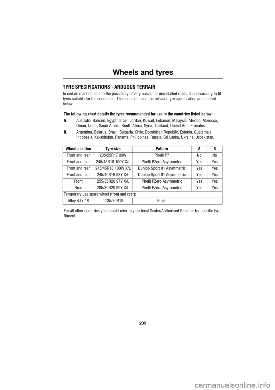
TYRE SPECIFICATIONS - ARDUOUS TERRAIN
In certain markets, due to the possibility of very uneven or unmetalled roads, it is necessary to fit
tyres suitable for the conditions. These markets and the relevant tyre specification are detailed
below.
The following chart details the tyres recomm ended for use in the countries listed below:
A . Australia, Bahrain, Egypt, Is rael, Jordan, Kuwait, Lebanon, Malaysia, Mexico, Morocco,
Oman, Qatar, Saudi Arabia, South Africa, Syria, Thailand, United Arab Emirates.
B . Argentina, Belarus, Brazil, Bulgaria, Chile, Dominican Republic, Estonia, Guatemala,
Indonesia, Kaxakhstan, Panama, Philippines, Russia, Sri Lanka, Ukraine, Uzbekistan.
Wheel position Tyre size PatternA B
Front and rear 235/55R17 99W Pirelli P7No No
Front and rear 245/45R18 100Y X/L Pir elli PZero Asymmetric Yes Yes
Front and rear 245/45R18 100W X/ L Dunlop Sport 01 Asymmetric Yes Yes
Front and rear 245/40R19 98Y X/L D unlop Sport 01 Asymmetric Yes Yes
Front 255/35R20 97Y X/L Pirelli PZero Asymmetric Yes Yes Rear 285/30R20 99Y X/L Pirelli PZero Asymmetric Yes Yes
Temporary use spare wheel (front and rear):
Alloy 4J x 18 T135/80R18 Pirelli
For all other countries you should refer to your local Dealer/Aut horised Repairer for specific tyre
fitment.
Page 241 of 391

241
Fuses
CHANGING A FUSE
Note: Jaguar recommend that owners do not
remove or replace rela ys. It is recommended
that you seek qualified assistance in the event
of a rela y failure.
Always switch off the i gnition and the affected
electrical circuit, be fore replacing a fuse.
Fuse failure is identifi ed by an inoperative
circuit.
A special tool for remo ving and replacing Mini
fuses is provided in the engine compartment
fuse box, together with spare fuses. Two types of fuses are fitted in the fuse boxes:
1.
Mini-type
2. J-Case
If a spare fuse is used, renew it (or have it
renewed) with a fuse of the same amperage
rating.
Push the tool onto the suspect fuse and
withdraw it.
If the wire in the fuse is broken, the fuse has
blown.
Fit a new fuse using the tool.
Checking or renewing a blown fuse
J-Case fuses ( 2) and relays should only be
replaced by a qualified technician.
Fuses are colour coded according to the
amperage and the rating is also marked on
each fuse.
CAUTIONS
Always turn off the ignition system and
the affected electrical circuit, before
replacing a fuse.
Fit Jaguar approved replacement fuses
of the same rating and type, or fuses of
matching specification. Using an incorrect
fuse may result in damage to the vehicle's
electrical system, and can result in a fire.
No attempt should be made to repair a
fuse that has blown.
If the replacement fuse blows after
installation, the system should be
checked by your Dealer /Authorised Repairer.
12
E95262
Page 252 of 391

Status after a collision
252
When driving
When driving a vehicle which has been
involved in a collision use caution and pay extra
attention to the operation of the vehicle. If any
changes in vehicle operation after the collision
are noted when compared to it's operation
before the collision, do not continue to drive
the vehicle. Stop the vehi cle as soon as it is
safe to do so, and have the vehicle recovered.
Pay particular attent ion to changes in:-
• Steering.
• Braking.
• Unusual noises.
• Warning lights or messages displayed.
• Problems with electrical systems.
INSPECTING SAFETY SYSTEM
COMPONENTS
Following a collision the seat belt and
Supplementary Restrain t System components
should be inspected for damage and/or
deformity. The inspection and any subsequent
repair work should only be carried out by a
Dealer/Authorised Repair er, or other suitably
qualified personnel.
Components which require inspection
include:-
• Seat belt webbing and mechanisms.
• Seat belt pre-tensioners.
• Airbag covers and modules.
• Seat frames a nd mounting points.
• Child seats.
• Child seat anchor points.
• Pedestrian prot ection system.
Note: This list is not exhaustive.
In addition to the physical items checked, the
electronic control system and its associated
wiring should also be checked thoroughly. This
process will include a diagnostic check which
can only be carried out by a Dealer/Authorised
repairer or suitably qualified and equipped
persons.
WARNING
It is not recommended that the
vehicle be driven or used until all of
the occupant protection systems
have been checked.
Page 253 of 391

253
Vehicle recovery
TOWING POINTS
Front and rear towing eyes and lashing points
The front and rear towing eyes are the only
recommended lashing points on the vehicle.
Attaching the front towing eye
The front towing eye is included in the tool kit,
located in the under-floor area of the luggage
compartment. See TOOL KIT (page 224).
1. Press the lower edge of the towing eye
cover in the front bumper to open, then
pull from the aperture, allowing the cover
to hang from its retaining strap.
2. Locate the towing eye through the bumper
and screw the towing eye
counter-clockwise into its fixing, until
secure.
E95301
1
2
WARNINGS
The towing eyes at the front and rear
of the vehicle are designed for
on-road recovery only. If they are
used for any purpose other than those
indicated, it may result in vehicle damage and
serious injury.
Never use the towing eyes to tow a
trailer, caravan etc. Doing so may
result in vehicle damage and serious
injury.
CAUTION
Only use the lashing points indicated, or
over-tyre tie-downs, to secure the
vehicle to the transporter or trailer. Use of any
other position (e.g. lower control arms) may
result in damage to the vehicle.
Page 254 of 391

Vehicle recovery
254
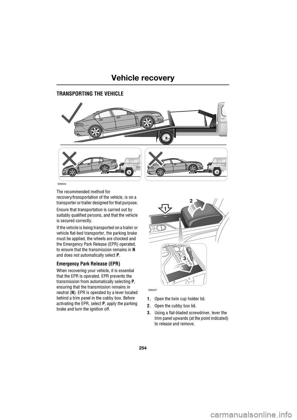
TRANSPORTING THE VEHICLE
The recommended method for
recovery/transportation of the vehicle, is on a
transporter or trailer de signed for that purpose.
Ensure that transporta tion is carried out by
suitably qualified persons , and that the vehicle
is secured correctly.
If the vehicle is being tr ansported on a trailer or
vehicle flat-bed transporter, the parking brake
must be applied, the wheels are chocked and
the Emergency Park Re lease (EPR) operated,
to ensure that the transmission remains in N
and does not automatically select P.
Emergency Park Release (EPR)
When recovering your vehicle, it is essential
that the EPR is operated. EPR prevents the
transmission from automatically selecting P,
ensuring that the transmission remains in
neutral ( N). EPR is operated by a lever located
behind a trim panel in the cubby box. Before
activating the EPR, select P, apply the parking
brake and turn the ignition off. 1.
Open the twin cup holder lid.
2. Open the cubby box lid.
3. Using a flat-bladed screwdriver, lever the
trim panel upwards (at the point indicated)
to release and remove.
E95304
2
3
E96407
1
Page 255 of 391

255
Vehicle recovery
4.Using a flat-bladed screwdriver, turn the
locking device 90° counter-clockwise.
5. Apply the foot brake.
6. Use the strap to pull the EPR lever
upwards, until it latches in the vertical
position.
When EPR is activated, the JaguarDrive
selector will remain in P , but the selector
indicator and the gear display in the message
centre will both flash N (if ignition is on), to
indicate that EPR is active.
When vehicle transportation has been
completed, EPR should be cancelled, to allow
Park to be re-engaged.
Cancelling EPR
1. Using a flat-bladed sc rewdriver, release
the latch (arrowed).
2. Return the EPR lever to its horizontal
position.
3. Turn the locking device 90° clockwise to
secure.
4. Replace the trim pane l and close the cubby
box and twin cup holder lids.E96408
4
5
62
1
E96409
3
Page 256 of 391

Vehicle recovery
256
TOWING THE VEHICLE ON FOUR
WHEELS
Note: The recommended recovery method is
to raise all four wheels.
Towing procedure
1. The vehicle should be parked on firm level
ground, with the parking brake on, and the
gear selector in P (Park).
2. Secure the towing attachment from the
recovery vehicle to the front towing eye.
See TOWING POINTS (page 253).
3. Dock the Jaguar Smart Key and switch on
the ignition. See GENERAL INFORMATION
(page 132). 4.
Apply the foot brake and release the
parking brake.
5. With the foot brake st ill applied, activate
the Emergency Park Release (EPR).
See TRANSPORTING THE VEHICLE
(page 254).
6. The vehicle can now be towed a maximum
of 0.8 km (0.5 miles) at a maximum speed
of 48 kmh (30 mph).
7. Upon arrival at the destination, ensure
wherever possible that the vehicle is
parked on firm level ground.
8. Lower the Emergency Park Release (EPR)
lever, to cancel EP R and to re-engage P
(Park).
9. Apply the parking brake.
10. Switch off the ignition and remove the
Jaguar Smart Key.
11. Remove the towing attachment from the
towing eye.
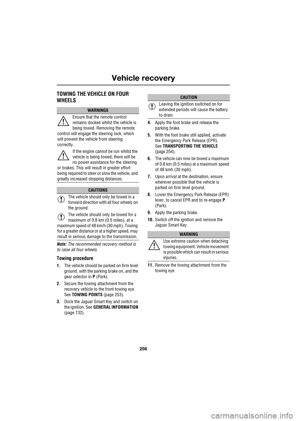
WARNINGS
Ensure that the remote control
remains docked whilst the vehicle is
being towed. Removing the remote
control will engage the steering lock, which
will prevent the vehicle from steering
correctly.
If the engine cannot be run whilst the
vehicle is being towed, there will be
no power assistance for the steering
or brakes. This will result in greater effort
being required to steer or slow the vehicle, and
greatly increased stopping distances.
CAUTIONS
The vehicle should only be towed in a
forward direction with all four wheels on
the ground.
The vehicle should only be towed for a
maximum of 0.8 km (0.5 miles), at a
maximum speed of 48 km/h (30 mph). Towing
for a greater distance or at a higher speed, may
result in serious damage to the transmission.
CAUTION
Leaving the ignition switched on for
extended periods will cause the battery
to drain.
WARNING
Use extreme caution when detaching
towing equipment. Vehicle movement
is possible which can result in serious
injuries.