2009 JAGUAR XF Disable vehicle
[x] Cancel search: Disable vehiclePage 65 of 391

65
Child safety
CHILD SAFETY LOCKS
Child safety locks are fitted to the rear doors to
allow you to prevent accidental opening of the
doors when the vehicle is in motion.
If children are to be carried in the rear seat
positions, it is recommended that the rear door
interior handles are disabled.
Note: For convenience, the rear door interior
handles should be re-e nabled when carrying
adult passengers in th e rear seat positions.
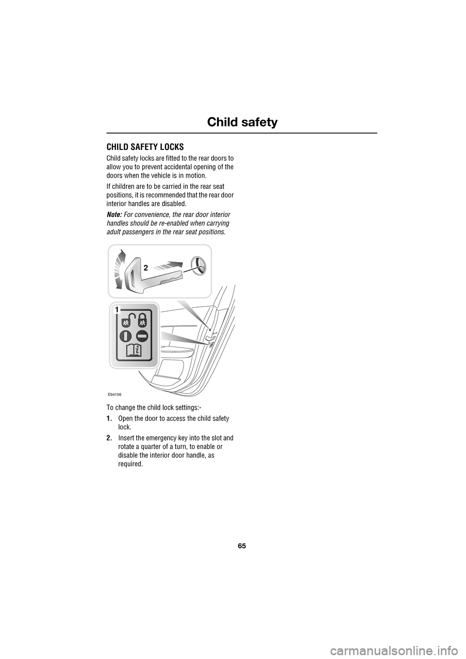
To change the child lock settings:-
1. Open the door to access the child safety
lock.
2. Insert the emergency key into the slot and
rotate a quarter of a turn, to enable or
disable the interior door handle, as
required.
E94106
1
2
Page 78 of 391

Lighting
78
DIRECTION INDICATORS
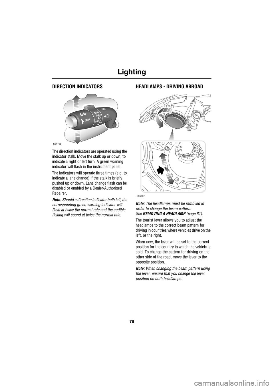
The direction indicators are operated using the
indicator stalk. Move the stalk up or down, to
indicate a right or left turn. A green warning
indicator will flash in the instrument panel.
The indicators will operate three times (e.g. to
indicate a lane change) if the stalk is briefly
pushed up or down. Lane change flash can be
disabled or enabled by a Dealer/Authorised
Repairer.
Note: Should a direction indicator bulb fail, the
corresponding green warning indicator will
flash at twice the normal rate and the audible
ticking will sound at twice the normal rate.
HEADLAMPS - DRIVING ABROAD
Note: The headlamps must be removed in
order to change the beam pattern.
See REMOVING A HEADLAMP (page 81).
The tourist lever allows you to adjust the
headlamps to the correct beam pattern for
driving in countries wher e vehicles drive on the
left, or the right.
When new, the lever will be set to the correct
position for the country in which the vehicle is
sold. To change the pattern for driving on the
other side of the road, move the lever to the
opposite position.
Note: When changing the beam pattern using
the lever, ensure that you change the lever
position on both headlamps.
E91163
E94707
Page 98 of 391

Windows and mirrors
98
BSM is designed to work most effectively when
driving on multi-lane highways.
If an object is identified by the system as being
an overtaking vehicle/object, an amber
warning icon ( 1) illuminates in the relevant
exterior mirror, to alert the driver that there is a
potential hazard in the vehicle's blind spot and
therefore, that a lane change might be
dangerous.
Note: If an overtaking vehicle is detected on
both sides of the vehicle simultaneously, the
warning icons in both mirrors will illuminate.
Note: BSM is automatically turned off when
reverse ( R) gear is selected, when the vehicle is
in park ( P), the vehicle is travelling below
16 km/h (10 mph) and also when the electrical
connector for the trailer socket is plugged in on
vehicles with a factory-fitted towing bracket.
When in these conditions, an amber warning
indicator within the exterior mirror is
displayed.Sensor blockage
The BSM system will automatically disable if
either of the sensors become completely
obscured, an amber wa rning indicator dot (2)
is displayed in the exterior mirror and the
message BSM sensor blocked appears in the
message centre.
Note: Blockage testing is only initiated when
vehicle speed is above 32 km/h (20 mph) and
will take at least two minutes of accumulated
time travelling above th is speed, to determine
that the sensor is blocked.
If the sensors become blocked, then please
check that there is nothing obscuring the rear
bumper and that it is cl ear from ice, frost and
dirt.
System fault
If a fault with one of the radar sensors is
detected, an amber warn ing indicator dot is
displayed in the exterior mirror and the
message BSM not available is displayed in the
message centre.
Note: Even if the detected fault only affects the
radar sensor on one side of the vehicle, the
whole system is disabled. If the fault is
temporary, the system will operate correctly
once the engine has been switched off and then
on again.
If a fault in the system occurs, consult your
Dealer/Authorised Repairer.
E96411
12
Page 125 of 391

125
Convenience features
AUXILIARY POWER SOCKETS
The auxiliary power socket is located in the
cubby box.
GLOVE BOX
The glove box is opened using the
JaguarSense proximity sensor on the fascia
(arrowed). To open the glove box, place the tip
of your finger close to and directly over the
sensor, as shown in the left-hand inset of the
illustration.
The sensor is able to distinguish between a
finger approach and an accidental finger rub
approach from a knee or other large items,
including being wiped for cleaning purposes.
Under these conditions, the sensor will not
react to the input and th e glove box will remain
closed.
Note: When the vehicle alarm is armed or Valet
mode is selected, the proximity sensor is
disabled, preventing the glove box from being
opened.
Note: The wearing of gloves may interfere with
the operation of the prox imity sensor. If gloves
are worn, it may be necessary to touch the
sensor to open the glove box.
CAUTIONS
Only Jaguar approv ed accessories
should be plugged into the power
sockets. Using any other equipment may
damage the vehicle's electrical system. If you
are in any doubt contact your Dealer/
Authorised Repairer.
The engine should be running when
using accessories for long periods.
Failure to do so can discharge the battery.
E95111
JAG1653
Page 143 of 391

143
Transmission
Limp-home mode
Note: The driver should be aware that the
vehicle’s performance will be reduced and
must take this into account when driving. Also
the use of the Jaguar Sequential Shift paddles
will be disabled. In this event, seek qualified
assistance as soon as possible.
In the unlikely event of an electrical or
mechanical failure, tran smission operation will
be limited. The vehicle gear selector ranges P,
R , N , D and S may still be used to enable the
vehicle to be driven to a safe area.
Some faults will cause the selector to be locked
in position until the igniti on is switched off. If
the selected range flashes, it signifies that the
driver request cannot be engaged. Re-select N
and repeat the attempt.
If the transmission is still unable to select the
requested gear, contact your Dealer/
Authorised Repairer.
Message centre display
The message centre will confirm the
JaguarDrive selector pos ition (selected gear). Selector position is sh
own highlighted at the
top of the message cent re and confirmed by
the dot on the circular representation of the
selector.
If manual mode is se lected, the numbers 1 to 6
appear at the top of the display, with the
currently selected gear highlighted.
Note: With the transmission set to permanent
manual mode and Dynamic mode selected,
when the rev limit is re ached, the gear position
indicator in the message centre will glow
amber, to indicate that the next gear should be
selected.
The message centre may also display the
following messages with associated warning
indicators:
ENGINE SYSTEMS FAULT (Red)
RESTRICTED PERFORMANCE (Red or Amber)
GEARBOX FAULT (Amber)
If any of these messages are displayed it is
likely that loss of power or driveability will be
experienced. Seek qualified assistance as soon
as possible.
A
km
l/100km
JAG1629
Page 151 of 391

151
Parking aid
The front or rear warning tone will become
continuous when the obstacle is detected at or
within 300 mm (12 inches) from the vehicle.
Note: The outer front and rear sensors will
switch off if the distance to an object increases
or remains constant for 3 seconds. The
sensors will reactivate automatically if a new
object is detected with in the operating range,
or if the distance to the original object reduces.
Rear fitted accessories
Particular care must be taken when reversing
with rear fitted accessories e.g. bicycle carrier,
as the rear park assist will only indicate the
distance from the bumper to the obstacle.
Cleaning the sensors
Do not clean the sensors with abrasive or sharp
objects or materials.
For reliable operation, th e sensors in the front
and rear bumpers should be kept free from ice,
frost and grime.
When using a high pressure spray the sensors
should only be sprayed br iefly and not from a
distance of less than 200 mm (8 inches).
System fault
If the system has a fault when engaging reverse
gear or turning on the ignition, then a single,
three second tone will be heard (only once per
ignition cycle) and a pop-up warning will
appear on the touch-scre en. If both front and
rear parking aids are fitted, the warning
indicator in the parking aid switch will flash for
three seconds and then switch off, if a fault is
detected.
If a fault is detected, the system is
automatically disabled.
The parking aid may sound spurious tones if it
detects a frequency tone using the same band
as the sensors (e.g. air brakes).
Page 184 of 391

Towing
184
Diesel engine vehicles
The diesel engine management system
incorporates sensors to determine optimum
performance. It is also designed to protect the
engine when arduous conditions are
encountered during towing. When ambient
temperature exceeds 40°C (104°F), the engine
coolant temperature may increase above
normal operating level. If this occurs, the
management system will initiate a series of
actions to restore norma l operating conditions.
The actions may include:
• A message centre message.
• Engine performance reduction.
• Air conditioning syst em cycling. The
system temperature output will fluctuate
between hot and cold, in order to dissipate
engine heat. If engine overheat persists,
the air conditioning will move to
continuous heat output.
It is advisable to bring the vehicle and trailer to
a convenient stop and allow the engine to idle
until normal temperature is restored. Do not
turn off the engine.
Trailer electrical connection
Note: The rear parking sensors are
automatically disabled when the trailer
electrical conne ction is made using Jaguar
approved towing equipment.
The vehicle's electrical system has been
designed to support all towing requirements,
and comply with legal requirements for the
specific territory in which the vehicle is first
sold.
LEVELLING
To maintain vehicle stabilit y, it is essential that
the trailer is loaded so that it remains parallel to
the ground. This is particularly important when
towing twin axled trailers.
CAUTION
Only connect appr oved electrical
circuits, which are in good condition to
the trailer socket. Connecting incorrect, or
faulty circuits may seriously damage the
vehicle's electrical circuits.
E95506
Page 214 of 391

Vehicle battery
214
USING BOOSTER CABLES
Note: Before connecti ng booster cables,
ensure that the battery connections on the
disabled vehicle are correct and that all
electrical equipment has been switched off.
1. Connect one end of the positive booster
cable to the positive terminal on the donor
vehicle's battery.
2. Connect the other end of the positive
booster cable to the positive terminal on
the disabled vehicle's battery. 3.
Connect one end of th e negative booster
cable to the earth point of the donor vehicle
that is recommended for jump starting by
the manufacturer.
4. Connect the other end of the negative
booster cable to a suitable earth point on
the disabled vehicle. The earth point
should be at least 0.5 metres (20 inches)
away from the battery and as far as
possible from any fu el or brake pipes.
• Check that all cables are clear of any
moving components and that all four
connections are secure.
5. Start the engine of the donor vehicle, and
allow it to idle for a few minutes.
6. Start the engine of the disabled vehicle.
7. Allow both vehicles to idle for two minutes.
8. Switch off the donor vehicle.
Disconnecting the cables
Note: Do not switch on any electrical
equipment until after th e cables have been
disconnected.
The engine should be running on the
previously disabled ve hicle and the engine
switched off on the donor vehicle. Disconnect
the booster cables in the exact reverse order of
that used for connection.
WARNINGS
Always wear appropriate eye
protection when working with
batteries.
During normal use, batteries emit
explosive hydrogen gas - ensure
sparks and naked lights are kept away
from the luggage compartment.
Do not attempt to start the vehicle if
the electrolyte in the battery is
suspected of being frozen.
Make sure both batt eries are of the 12
volt type and that the booster cables
have insulated clamps and are
approved for use with 12 volt batteries.
Do not disconnect the discharged
battery.
Do not connect posit ive (+) terminals
to negative (-) terminals and ensure
booster cables are kept away from
any moving parts in the engine compartment.
Do not connect a booster cable to the
negative (-) terminal of the battery.
Always connect to the recommended
earthing point.
WARNING
To avoid serious in jury use extreme
caution when removing the booster
cables as the engine will be running
on the previously disabl ed vehicle. This means
that you may be workin g close to components
which are moving at high speed, carry high
voltage, or may be hot.