2009 INFINITI QX56 sensor
[x] Cancel search: sensorPage 3427 of 4171
SN
INSPECTION AND ADJUSTMENTSN-5
< BASIC INSPECTION >
C
DE
F
G H
I
J
K L
M B A
O P
INSPECTION AND ADJUSTMENT
Preliminary CheckINFOID:0000000003776738
DESCRIPTION
The purpose of the sonar sensor preliminary check is to confirm that there are no outside factors affecting the
sonar system.
CONDITIONS
• Ignition switch ON
• No obstructions within 3.0 m (10 ft.) of sonar sensors
SONAR SENSOR STATUS CHECK
• Check that the sonar sensors are properly aligned (no deformation in sensor mounting areas).
• Check that snow, mud or other foreign obj ects are not adhering to the sonar sensors.
• Check that there is no deformation, scratc hes or other damage to the sonar sensors.
• Check that water has not accu mulated in the sonar sensors.
CAUTION:
Use water, cotton swab, or other soft material for cleaning the sensors.
1. Check that there are no obstacles wit hin each sonar sensor's detection range.
2. Check that there are no nearby ultrasound sources such as the sounds of vehicle horns, motorcycle
engines or truck air brakes.
3. Check that the vehicle is on a level surface.
Sonar sensors Detection range
Front Approx. 1.0 m (3 ft.) maximum
Rear Approx. 1.8 m (5.9 ft.) maximum
Revision: December 20092009 QX56
Page 3428 of 4171
SN-6
< FUNCTION DIAGNOSIS >
REAR SONAR SYSTEM
FUNCTION DIAGNOSIS
REAR SONAR SYSTEM
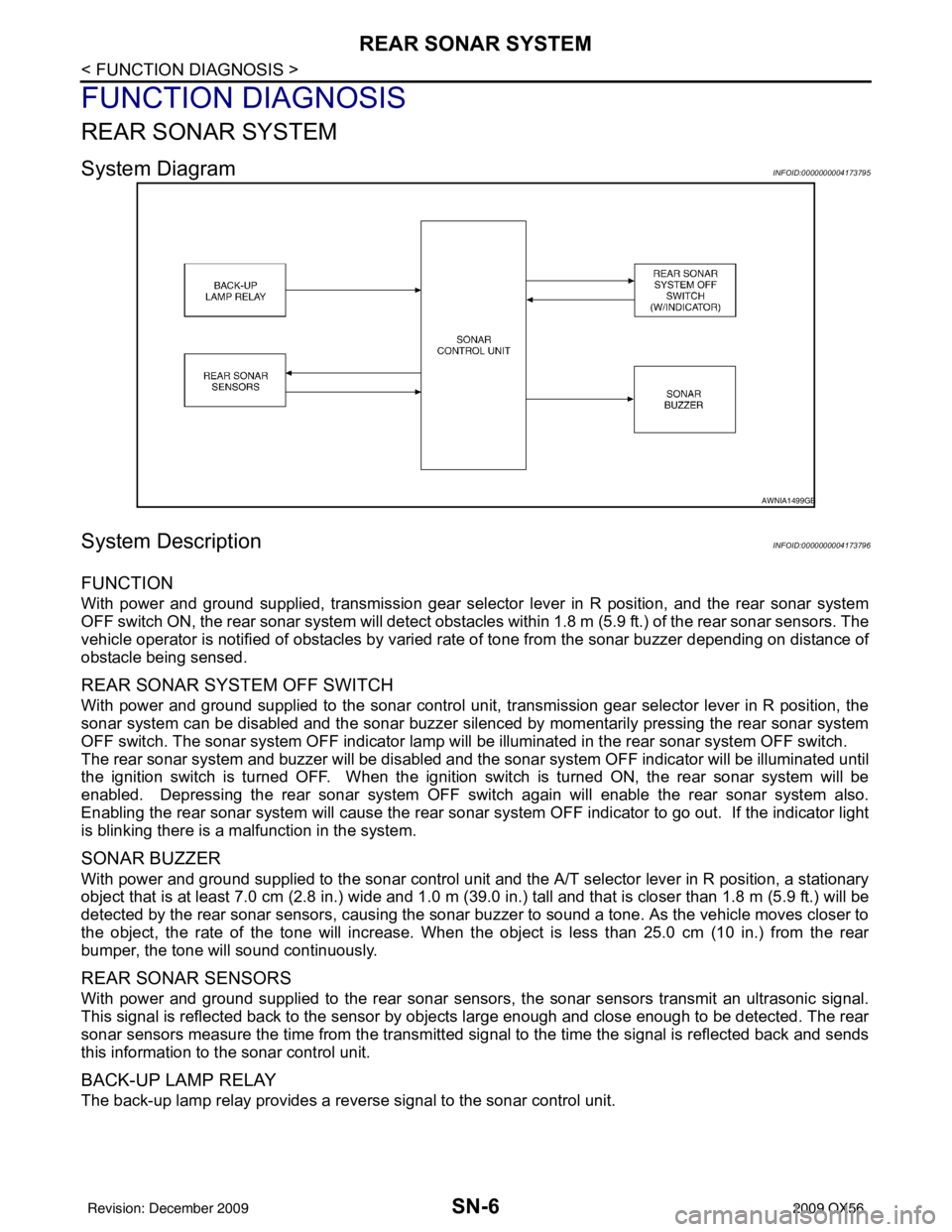
System DiagramINFOID:0000000004173795
System DescriptionINFOID:0000000004173796
FUNCTION
With power and ground supplied, transmission gear selector lever in R position, and the rear sonar system
OFF switch ON, the rear sonar system will detect obstacles within 1.8 m (5.9 ft.) of the rear sonar sensors. The
vehicle operator is notified of obstacles by varied rate of tone from the sonar buzzer depending on distance of
obstacle being sensed.
REAR SONAR SYSTEM OFF SWITCH
With power and ground supplied to the sonar control unit, transmission gear selector lever in R position, the
sonar system can be disabled and the sonar buzzer silenced by momentarily pressing the rear sonar system
OFF switch. The sonar system OFF indicator lamp will be illuminated in the rear sonar system OFF switch.
The rear sonar system and buzzer will be disabled and t he sonar system OFF indicator will be illuminated until
the ignition switch is turned OFF. When the ignition switch is turned ON, the rear sonar system will be
enabled. Depressing the rear sonar system OFF s witch again will enable the rear sonar system also.
Enabling the rear sonar system will cause the rear sonar system OFF indicator to go out. If the indicator light
is blinking there is a malfunction in the system.
SONAR BUZZER
With power and ground supplied to the sonar control unit and the A/T selector lever in R position, a stationary
object that is at least 7.0 cm (2.8 in.) wide and 1.0 m (39. 0 in.) tall and that is closer than 1.8 m (5.9 ft.) will be
detected by the rear sonar sensors, causing the sonar buzzer to sound a tone. As the vehicle moves closer to
the object, the rate of the tone will increase. When the object is less than 25.0 cm (10 in.) from the rear
bumper, the tone will sound continuously.
REAR SONAR SENSORS
With power and ground supplied to the rear sonar sens ors, the sonar sensors transmit an ultrasonic signal.
This signal is reflected back to the sensor by objects large enough and close enough to be detected. The rear
sonar sensors measure the time from the transmitted si gnal to the time the signal is reflected back and sends
this information to the sonar control unit.
BACK-UP LAMP RELAY
The back-up lamp relay provides a reverse signal to the sonar control unit.
AWNIA1499GB
Revision: December 20092009 QX56
Page 3429 of 4171
SN
REAR SONAR SYSTEMSN-7
< FUNCTION DIAGNOSIS >
C
DE
F
G H
I
J
K L
M B A
O P
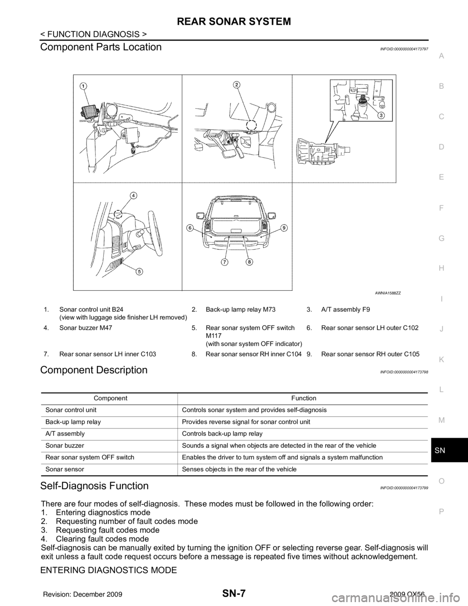
Component Parts LocationINFOID:0000000004173797
Component DescriptionINFOID:0000000004173798
Self-Diagnosis FunctionINFOID:0000000004173799
There are four modes of self-diagnosis. Thes e modes must be followed in the following order:
1. Entering diagnostics mode
2. Requesting number of fault codes mode
3. Requesting fault codes mode
4. Clearing fault codes mode
Self-diagnosis can be manually exited by turning the igni tion OFF or selecting reverse gear. Self-diagnosis will
exit unless a fault code request occurs before a me ssage is repeated five times without acknowledgement.
ENTERING DIAGNOSTICS MODE
1. Sonar control unit B24
(view with luggage side finisher LH removed) 2. Back-up lamp relay M73 3. A/T assembly F9
4. Sonar buzzer M47 5. Rear sonar system OFF switch
M117
(with sonar system OFF indicator) 6. Rear sonar sensor LH outer C102
7. Rear sonar sensor LH inner C103 8. Rear sonar sensor RH inner C104 9. Rear sonar sensor RH outer C105
AWNIA1588ZZ
Component Function
Sonar control unit Controls sonar system and provides self-diagnosis
Back-up lamp relay Provides reverse signal for sonar control unit
A/T assembly Controls back-up lamp relay
Sonar buzzer Sounds a signal when objects are detected in the rear of the vehicle
Rear sonar system OFF switch Enables the driver to turn system off and signals a system malfunction
Sonar sensor Senses objects in the rear of the vehicle
Revision: December 20092009 QX56
Page 3432 of 4171
SN-10
< FUNCTION DIAGNOSIS >
FRONT AND REAR SONAR SYSTEM
FRONT AND REAR SONAR SYSTEM
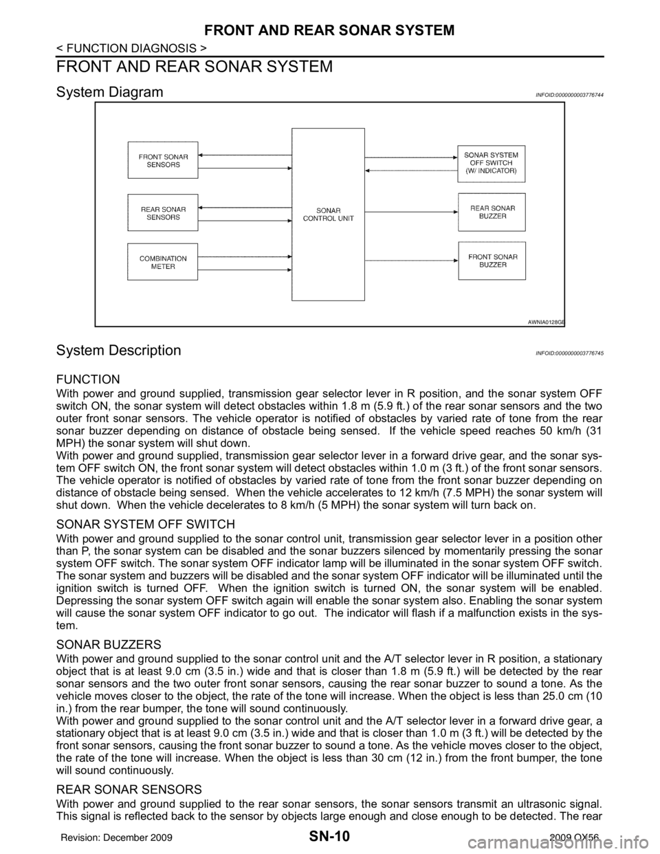
System DiagramINFOID:0000000003776744
System DescriptionINFOID:0000000003776745
FUNCTION
With power and ground supplied, transmission gear selector lever in R position, and the sonar system OFF
switch ON, the sonar system will detect obstacles within 1.8 m (5.9 ft.) of the rear sonar sensors and the two
outer front sonar sensors. The vehicle operator is notif ied of obstacles by varied rate of tone from the rear
sonar buzzer depending on distance of obstacle being sens ed. If the vehicle speed reaches 50 km/h (31
MPH) the sonar syst em will shut down.
With power and ground supplied, transmission gear selector lever in a forward drive gear, and the sonar sys-
tem OFF switch ON, the front sonar system will detect obstacles within 1.0 m (3 ft.) of the front sonar sensors.
The vehicle operator is notified of obstacles by varied rate of tone from the front sonar buzzer depending on
distance of obstacle being sensed. When the vehicle accelerates to 12 km/h (7.5 MPH) the sonar system will
shut down. When the vehicle decelerates to 8 km/h (5 MPH) the sonar system will turn back on.
SONAR SYSTEM OFF SWITCH
With power and ground supplied to the sonar control unit, transmission gear selector lever in a position other
than P, the sonar system can be di sabled and the sonar buzzers silenced by momentarily pressing the sonar
system OFF switch. The sonar system OFF indicator lamp will be illuminated in the sonar system OFF switch.
The sonar system and buzzers will be di sabled and the sonar system OFF indicator will be illuminated until the
ignition switch is turned OFF. When the ignition switch is turned ON, the sonar system will be enabled.
Depressing the sonar system OFF switch again will enabl e the sonar system also. Enabling the sonar system
will cause the sonar system OFF indicator to go out. The indicator will flash if a malfunction exists in the sys-
tem.
SONAR BUZZERS
With power and ground supplied to the sonar control unit and the A/T selector lever in R position, a stationary
object that is at least 9.0 cm (3.5 in.) wide and that is closer than 1.8 m (5.9 ft.) will be detected by the rear
sonar sensors and the two outer front sonar sensors, causing the rear sonar buzzer to sound a tone. As the
vehicle moves closer to the object, the rate of the tone will increase. When the object is less than 25.0 cm (10
in.) from the rear bumper, the tone will sound continuously.
With power and ground supplied to the sonar control unit and the A/T selector lever in a forward drive gear, a
stationary object that is at least 9.0 cm (3.5 in.) wide and that is closer than 1.0 m (3 ft.) will be detected by the
front sonar sensors, causing the front sonar buzzer to sound a tone. As the vehicle moves closer to the object,
the rate of the tone will increase. When the object is less than 30 cm (12 in.) from the front bumper, the tone
will sound continuously.
REAR SONAR SENSORS
With power and ground supplied to the rear sonar sens ors, the sonar sensors transmit an ultrasonic signal.
This signal is reflected back to the sensor by objects large enough and close enough to be detected. The rear
AWNIA0128GB
Revision: December 20092009 QX56
Page 3433 of 4171

SN
FRONT AND REAR SONAR SYSTEMSN-11
< FUNCTION DIAGNOSIS >
C
DE
F
G H
I
J
K L
M B A
O P
sonar sensors measure the time from the transmitted si gnal to the time the signal is reflected back and send
this information to the sonar control unit.
FRONT SONAR SENSORS
With power and ground supplied to the front sonar sens ors, the sonar sensors transmit an ultrasonic signal.
This signal is reflected back to the sensor by objects large enough and close enough to be detected. The front
sonar sensors measure the time from the transmitted si gnal to the time the signal is reflected back and send
this information to the sonar control unit.
COMBINATION METER
The combination meter provides the vehicle speed and park signals to the sonar control unit.
Component Parts LocationINFOID:0000000003776746
Front
1. Sonar control unit B56, B57 (View with luggage side finisher LH removed) 2. Back-up lamp relay M73 3. A/T assembly F9
4. Front sonar buzzer M118 5. Sonar system OFF switch M116
(with sonar system OFF indicator) 6. Rear sonar sensor LH outer C102
7. Rear sonar sensor LH inner C103 8. Rear sonar sensor RH inner C104 9. Rear sonar sensor RH outer C105
10. Front sonar sensor RH outer E166 11. Front sonar sensor RH inner E163 12. Front sonar sensor LH inner E162
13. Front sonar sensor LH outer E158 14. Combination meter M23, M24 15. Rear sonar buzzer B166
(View with back door open)
AWNIA1853ZZ
Revision: December 20092009 QX56
Page 3434 of 4171
SN-12
< FUNCTION DIAGNOSIS >
FRONT AND REAR SONAR SYSTEM
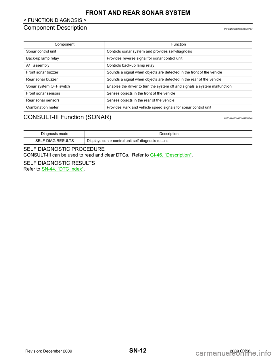
Component Description
INFOID:0000000003776747
CONSULT-III Function (SONAR)INFOID:0000000003776748
SELF DIAGNOSTIC PROCEDURE
CONSULT-III can be used to read and clear DTCs. Refer to GI-46, "Description".
SELF DIAGNOSTIC RESULTS
Refer to SN-44, "DTC Index".
Component Function
Sonar control unit Controls sonar system and provides self-diagnosis
Back-up lamp relay Provides reverse signal for sonar control unit
A/T assembly Controls back-up lamp relay
Front sonar buzzer Sounds a signal when objects are detected in the front of the vehicle
Rear sonar buzzer Sounds a signal when objects are detected in the rear of the vehicle
Sonar system OFF switch Enables the driver to turn the system off and signals a system malfunction
Front sonar sensors Senses objects in the front of the vehicle
Rear sonar sensors Senses objects in the rear of the vehicle
Combination meter Provides Park and vehicle speed signals for sonar control unit
Diagnosis mode Description
SELF-DIAG RESULTS Displays sonar control unit self-diagnosis results.
Revision: December 20092009 QX56
Page 3437 of 4171
SN
SONAR SENSOR CIRCUIT INSPECTIONSN-15
< COMPONENT DIAGNOSIS >
C
DE
F
G H
I
J
K L
M B A
O P
SONAR SENSOR CIRCUIT INSPECTION
DescriptionINFOID:0000000004173802
With power and ground supplied to the sonar sensors, the sonar sensors transmit an ultrasonic signal. This
signal is reflected back to the sensor by objec ts large enough and close enough to be detected. The sonar
sensors measure the time from the transmitted signal to the time the signal is reflected back and send this
information to the sonar control unit.
Diagnosis Procedure (With Rear Sonar System)INFOID:0000000004173803
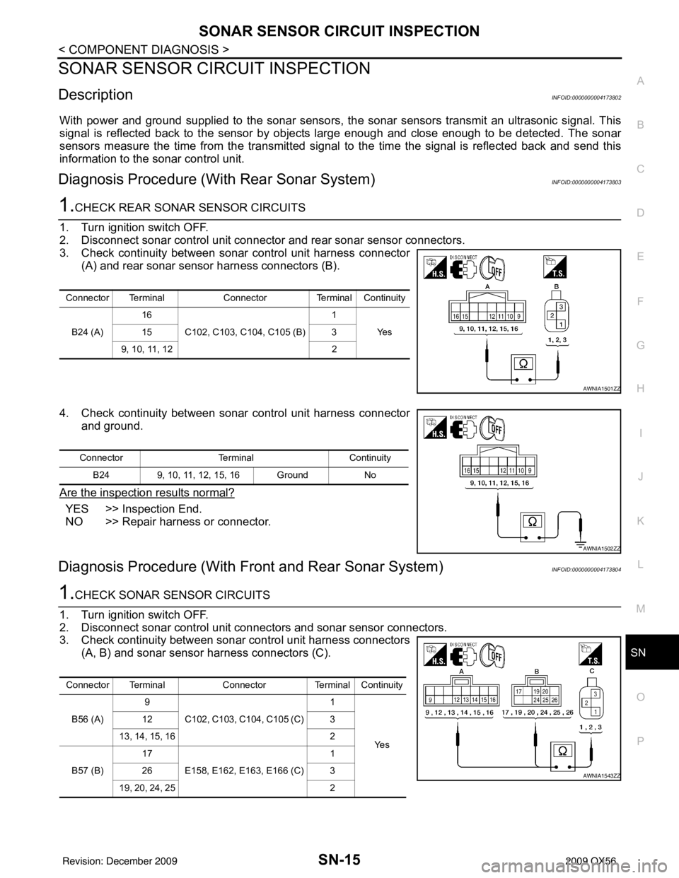
1.CHECK REAR SONAR SENSOR CIRCUITS
1. Turn ignition switch OFF.
2. Disconnect sonar control unit connector and rear sonar sensor connectors.
3. Check continuity between sonar control unit harness connector (A) and rear sonar sensor harness connectors (B).
4. Check continuity between sonar control unit harness connector and ground.
Are the inspection results normal?
YES >> Inspection End.
NO >> Repair harness or connector.
Diagnosis Procedure (With Front and Rear Sonar System)INFOID:0000000004173804
1.CHECK SONAR SENSOR CIRCUITS
1. Turn ignition switch OFF.
2. Disconnect sonar control unit connec tors and sonar sensor connectors.
3. Check continuity between sonar control unit harness connectors (A, B) and sonar sensor harness connectors (C).
Connector Terminal ConnectorTerminal Continuity
B24 (A) 16
C102, C103, C104, C105 (B) 1
Ye s
15 3
9, 10, 11, 12 2
AWNIA1501ZZ
ConnectorTerminalContinuity
B24 9, 10, 11, 12, 15, 16 Ground No
AWNIA1502ZZ
Connector TerminalConnectorTerminal Continuity
B56 (A) 9
C102, C103, C104, C105 (C) 1
Ye s
12
3
13, 14, 15, 16 2
B57 (B) 17
E158, E162, E1 63, E166 (C) 1
26 3
19, 20, 24, 25 2
AWNIA1543ZZ
Revision: December 20092009 QX56
Page 3438 of 4171
SN-16
< COMPONENT DIAGNOSIS >
SONAR SENSOR CIRCUIT INSPECTION
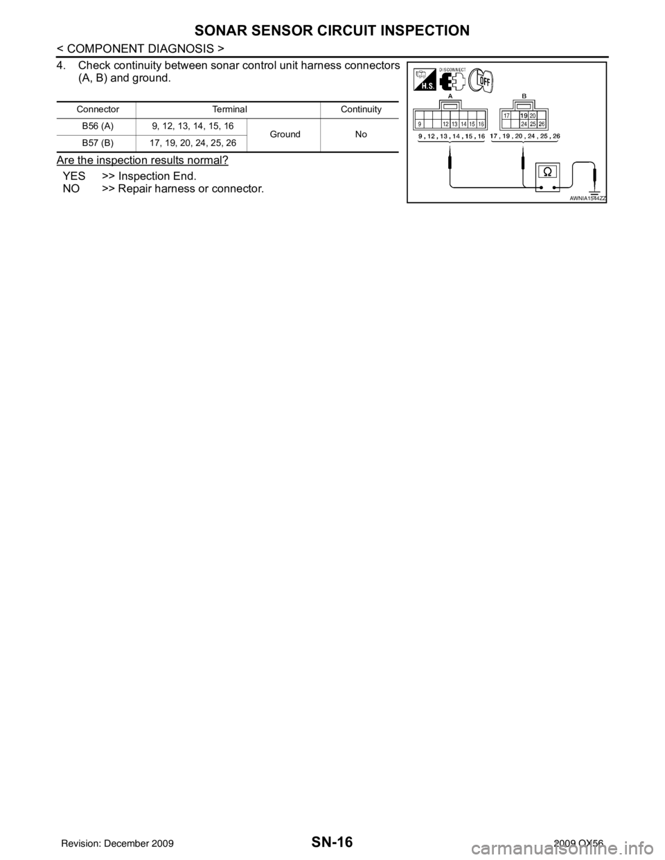
4. Check continuity between sonar control unit harness connectors
(A, B) and ground.
Are the inspection results normal?
YES >> Inspection End.
NO >> Repair harness or connector.
Connector TerminalContinuity
B56 (A) 9, 12, 13, 14, 15, 16 GroundNo
B57 (B) 17, 19, 20, 24, 25, 26
AWNIA1544ZZ
Revision: December 20092009 QX56