2009 INFINITI QX56 keyless
[x] Cancel search: keylessPage 2955 of 4171
POWER WINDOW SYSTEMPWC-7
< FUNCTION DIAGNOSIS >
C
DE
F
G H
I
J
L
M A
B
PWC
N
O P
ANTI-PINCH OPERATION
Pinch foreign material in the door glass during AUTO-U P operation, and it is the anti-pinch function that low-
ers the door glass 150 mm (5.91 in) or 2 seconds when detected.
Encoder continues detecting the movement of power window motor and transmits to power window switch
as the encoder pulse signal while power window motor is operating.
Resistance is applied to the power window motor ro tation that changes the frequency of encoder pulse sig-
nal if foreign material is trapped in the door glass.
Front power window switch LH/RH and rear power wi ndow control unit LH/RH controls to lower the window
glass for 150 mm (5.91 in) or 2 seconds after it detects encoder pulse signal frequency change.
OPERATION CONDITION
When all door glass AUTO-UP operation is performed ( anti-pinch function does not operate just before the
door glass closes and is fully closed)
NOTE:
Depending on environment and driving conditions, if a similar impact or load is applied to the door glass, it
may lower.
KEY CYLINDER SWITCH OPERATION
Hold the door key cylinder to the LOCK or UNLOCK direction for more than 1 second to OPEN or CLOSE front
power windows when ignition switch is OFF. In addition, it stops when key position is moved to NEUTRAL
when operating.
OPERATION CONDITION
Ignition switch OFF
Hold door key cylinder to LOCK position for more than 1 second to perform CLOSE operation of the door
glass.
Hold door key cylinder to UNLOCK position for more than 1 second to perform OPEN operation of the door glass.
KEYLESS POWER WINDOW DOWN OPERATION
Front power windows open when the unlock button on Intelli gent Key is activated and kept pressed for more
than 3
(NOTE) seconds with the ignition switch OFF. The wi ndows keep opening if the unlock button is continu-
ously pressed.
The power window opening stops when the following operations are performed:
When the unlock button is kept pressed more than 15 seconds.
When the ignition switch is turned ON while the power window opening is operated.
When the unlock button is released.
While retained power operation is activated, ke yless power window down function cannot be operated.
NOTE:
Keyless power window down operation mode can be changed by “PW DOWN SET” mode in “WORK SUP-
PORT”. Refer to DLK-56, "CONSULT-III F unction (INTELLIGENT KEY)"
.
NOTE:
Use CONSULT-III to change settings.
MODE1 (3sec)/MODE2 (OFF)/MODE3 (5sec)
Revision: December 20092009 QX56
Page 2958 of 4171

PWC-10
< FUNCTION DIAGNOSIS >
DIAGNOSIS SYSTEM (BCM)
DIAGNOSIS SYSTEM (BCM)
COMMON ITEM
COMMON ITEM : CONSULT-III Function (BCM - COMMON ITEM)INFOID:0000000004064497
APPLICATION ITEM
CONSULT-III performs the following functions via CAN communication with BCM.
SYSTEM APPLICATION
BCM can perform the following functions for each system.
NOTE:
It can perform the diagnosis modes except the following for all sub system selection items.
RETAINED PWR
RETAINED PWR : CONSULT-III Function (BCM - RETAINED PWR)INFOID:0000000004064498
Data monitor
Diagnosis mode Function Description
WORK SUPPORT Changes the setting for each system function.
SELF-DIAG RESULTS Displays the diagnosis results judged by BCM. Refer to BCS-51, "DTC Index"
.
CAN DIAG SUPPORT MNTR Monitors the reception status of CAN communication viewed from BCM.
DATA MONITOR The BCM input/output signals are displayed.
ACTIVE TEST The signals used to activate each device are forcibly supplied from BCM.
ECU IDENTIFICATION The BCM part number is displayed.
CONFIGURATION Enables to read and save the vehicle specification.
Enables to write the vehicle specification when replacing BCM.
System Sub system selection item Diagnosis mode
WORK SUPPORT DATA MONITOR ACTIVE TEST
BCM BCM ×
Door lock DOOR LOCK ×××
Rear window defo gger REAR DEFOGGER ×
Warning chime BUZZER ××
Interior room lamp timer INT LAMP ×××
Remote keyless entry system MULTI REMOTE ENT ××
Exterior lamp HEAD LAMP ×××
Wiper and washer WIPER ×××
Turn signal and hazard warning lamps FLASHER ××
Air conditioner AIR CONDITONER ×
Intelligent Key system INTELLIGENT KEY ×
Combination switch COMB SW ×
Immobilizer IMMU ××
Interior room lamp battery saver BATTERY SAVER ×××
Back door open TRUNK ××
RAP (retained accessory power) RETAINED PWR ×××
Signal buffer system SIGNAL BUFFER ××
TPMS (tire pressure monitoring sys-
tem) AIR PRESSURE MONITOR
×××
Vehicle security system PANIC ALARM ×
Revision: December 20092009 QX56
Page 2987 of 4171
POWER WINDOW SERIAL LINKPWC-39
< COMPONENT DIAGNOSIS >
C
DE
F
G H
I
J
L
M A
B
PWC
N
O P
POWER WINDOW SERIAL LINK
POWER WINDOW MAIN SWITCH
POWER WINDOW MAIN SWITCH : DescriptionINFOID:0000000003776012
Main power window and door lock/unlock switch, pow er window and door lock/unlock switch RH and BCM
transmit and receive the signal by power window serial link.
The signal mentioned below is transmitted from BCM to main power window and door lock/unlock switch and
power window and door lock/unlock switch RH
Keyless power window down signal
The signal mentioned below is transmitted from main power window and door lock/unlock switch to power win-
dow and door lock/unlock switch RH
Front door window RH operation signal
Power window control by key cylinder switch signal
Power window lock switch signal
Retained power operation signal
POWER WINDOW MAIN SWITCH : Component Function CheckINFOID:0000000003776013
1. CHECK MAIN POWER WINDOW AND DOOR LOCK/UNLOCK SWITCH OUTPUT SIGNAL
Check (“CDL LOCK SW ”, “CDL UNLOCK SW”) in “D ATA MONITOR” mode for “POWER DOOR LOCK SYS-
TEM” with CONSULT-III. Refer to BCS-17, "DOOR LOCK : CONSULT-II I Function (BCM - DOOR LOCK)"
.
Is the inspection result normal?
YES >> Power window serial link is OK.
NO >> Refer to PWC-39, "POWER WINDOW MAIN SWITCH : Diagnosis Procedure"
.
POWER WINDOW MAIN SWITCH : Diagnosis ProcedureINFOID:0000000003776014
Power Window Serial Link Check
1. CHECK MAIN POWER WINDOW AND DOOR LOCK/UNLOCK SWITCH OUTPUT SIGNAL
1. Remove Intelligent Key or ignition key, and close front door LH and RH.
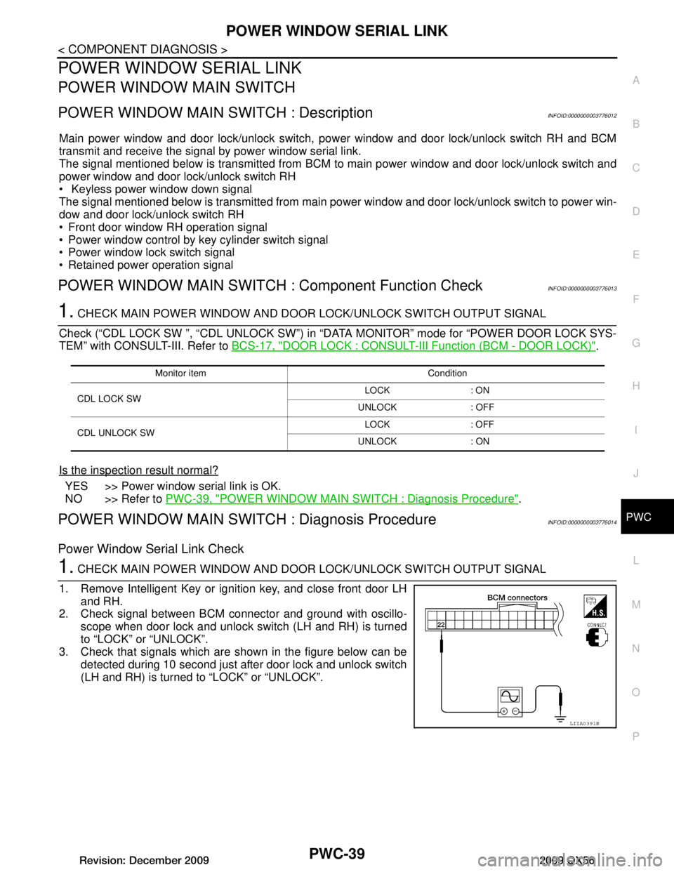
2. Check signal between BCM connector and ground with oscillo- scope when door lock and unlock switch (LH and RH) is turned
to “LOCK” or “UNLOCK”.
3. Check that signals which are shown in the figure below can be detected during 10 second just after door lock and unlock switch
(LH and RH) is turned to “LOCK” or “UNLOCK”.
Monitor item Condition
CDL LOCK SW LOCK : ON
UNLOCK : OFF
CDL UNLOCK SW LOCK : OFF
UNLOCK : ON
LIIA0391E
Revision: December 20092009 QX56
Page 2988 of 4171
PWC-40
< COMPONENT DIAGNOSIS >
POWER WINDOW SERIAL LINK
Is the inspection result normal?
YES >> Power window serial link is OK.
NO >> GO TO 2
2. CHECK POWER WINDOW SERIAL LINK CIRCUIT
1. Turn ignition switch OFF.
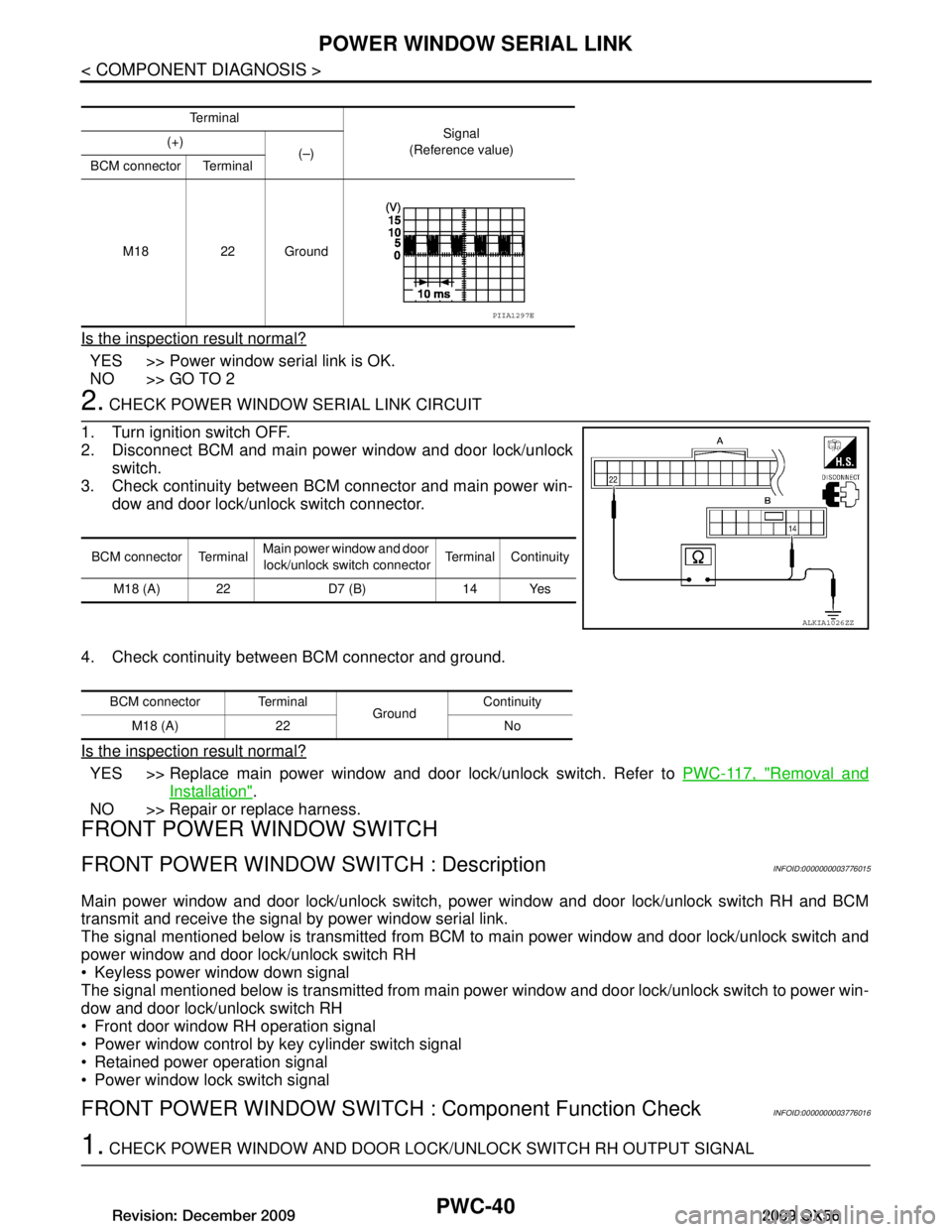
2. Disconnect BCM and main power window and door lock/unlock switch.
3. Check continuity between BCM connector and main power win- dow and door lock/unlock switch connector.
4. Check continuity between BCM connector and ground.
Is the inspection result normal?
YES >> Replace main power window and door lock/unlock switch. Refer to PWC-117, "Removal and
Installation".
NO >> Repair or replace harness.
FRONT POWER WINDOW SWITCH
FRONT POWER WINDOW SWITCH : DescriptionINFOID:0000000003776015
Main power window and door lock/unlock switch, power window and door lock/unlock switch RH and BCM
transmit and receive the signal by power window serial link.
The signal mentioned below is transmitted from BCM to main power window and door lock/unlock switch and
power window and door lock/unlock switch RH
Keyless power window down signal
The signal mentioned below is transmitted from main power window and door lock/unlock switch to power win-
dow and door lock/unlock switch RH
Front door window RH operation signal
Power window control by key cylinder switch signal
Retained power operation signal
Power window lock switch signal
FRONT POWER WINDOW SWITCH : Component Function CheckINFOID:0000000003776016
1. CHECK POWER WINDOW AND DOOR LO CK/UNLOCK SWITCH RH OUTPUT SIGNAL
Te r m i n a l
Signal
(Reference value)
(+)
(–)
BCM connector Terminal
M18 22 Ground
PIIA1297E
BCM connector Terminal Main power window and door
lock/unlock switch connector Terminal Continuity
M18 (A) 22 D7 (B) 14 Yes
ALKIA1026ZZ
BCM connector Terminal GroundContinuity
M18 (A) 22 No
Revision: December 20092009 QX56
Page 3005 of 4171
BCM (BODY CONTROL MODULE)PWC-57
< ECU DIAGNOSIS >
C
DE
F
G H
I
J
L
M A
B
PWC
N
O P
Te r m i n a l Wire
color Signal name Signal
input/
output Measuring condition
Reference value or waveform
(Approx.)
Ignition
switch Operation or condition
1BR/W Ignition keyhole illumi-
nation Output OFFDoor is locked (SW OFF) Battery voltage
Door is unlocked (SW ON) 0V
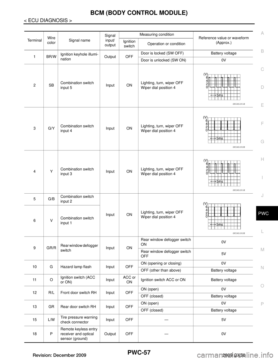
2SB Combination switch
input 5 Input ON
Lighting, turn, wiper OFF
Wiper dial position 4
3G/Y Combination switch
input 4 Input ONLighting, turn, wiper OFF
Wiper dial position 4
4Y Combination switch
input 3 Input ON
Lighting, turn, wiper OFF
Wiper dial position 4
5G/B Combination switch
input 2
Input ONLighting, turn, wiper OFF
Wiper dial position 4
6V Combination switch
input 1
9GR/R Rear window defogger
switch
Input ONRear window defogger switch
ON
0V
Rear window defogger switch
OFF 5V
10 G Hazard lamp flash Input OFF ON (opening or closing) 0V
OFF (other than above) Battery voltage
11 O Ignition switch (ACC
or ON)
InputACC or
ON Ignition switch ACC or ON Battery voltage
12 R/L Front door switch RH Input OFF ON (open) 0V
OFF (closed) Battery voltage
13 GR Rear door switch RH Input OFF ON (open) 0V
OFF (closed) Battery voltage
15 L/W Tire pressure warning
check connector
Input OFF — 5V
18 P Remote keyless entry
receiver and optical
sensor (ground)
Output OFF — 0V
SKIA5291E
SKIA5292E
SKIA5291E
SKIA5292E
Revision: December 20092009 QX56
Page 3006 of 4171
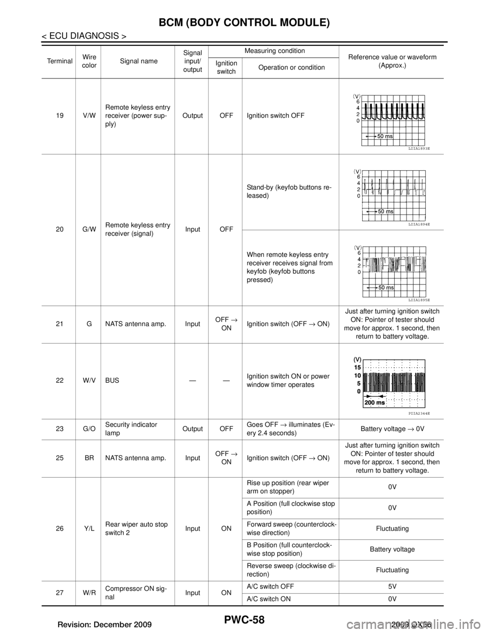
PWC-58
< ECU DIAGNOSIS >
BCM (BODY CONTROL MODULE)
19 V/WRemote keyless entry
receiver (power sup-
ply) Output OFF Ignition switch OFF
20 G/W Remote keyless entry
receiver (signal) Input OFFStand-by (keyfob buttons re-
leased)
When remote keyless entry
receiver receives signal from
keyfob (keyfob buttons
pressed)
21 G NATS antenna amp. Input OFF
→
ON Ignition switch (OFF
→ ON) Just after turning ignition switch
ON: Pointer of tester should
move for approx. 1 second, then return to battery voltage.
22 W/V BUS — — Ignition switch ON or power
window timer operates
23 G/O Security indicator
lamp Output OFF
Goes OFF
→ illuminates (Ev-
ery 2.4 seconds) Battery voltage
→ 0V
25 BR NATS antenna amp. Input OFF
→
ON Ignition switch (OFF
→ ON) Just after turning ignition switch
ON: Pointer of tester should
move for approx. 1 second, then return to battery voltage.
26 Y/L Rear wiper auto stop
switch 2 Input ONRise up position (rear wiper
arm on stopper)
0V
A Position (full clockwise stop
position) 0V
Forward sweep (counterclock-
wise direction) Fluctuating
B Position (full counterclock-
wise stop position) Battery voltage
Reverse sweep (clockwise di-
rection) Fluctuating
27 W/R Compressor ON sig-
nal Input ONA/C switch OFF 5V
A/C switch ON 0V
Te r m i n a l
Wire
color Signal name Signal
input/
output Measuring condition
Reference value or waveform
(Approx.)
Ignition
switch Operation or condition
LIIA1893E
LIIA1894E
LIIA1895E
PIIA2344E
Revision: December 20092009 QX56
Page 3060 of 4171

PWC-112
< SYMPTOM DIAGNOSIS >
KEYLESS POWER WINDOW DOWN DOES NOT OPERATE
KEYLESS POWER WINDOW DOWN DOES NOT OPERATE
Diagnosis ProcedureINFOID:0000000003776053
1. CHECK INTELLIGENT KEY FUNCTION
Check Intelligent Key function.
Refer to DLK-56, "CONSULT-III Func tion (INTELLIGENT KEY)"
.
Is the inspection result normal?
YES >> Check intermittent incident. Refer to GI-38, "Intermittent Incident".
NO >> Replace BCM. Refer to BCS-56, "Removal and Installation"
.
Revision: December 20092009 QX56
Page 3099 of 4171

RF-8
< FUNCTION DIAGNOSIS >
DIAGNOSIS SYSTEM (BCM)
DIAGNOSIS SYSTEM (BCM)
COMMON ITEM
COMMON ITEM : CONSULT-III Function (BCM - COMMON ITEM)INFOID:0000000005867481
APPLICATION ITEM
CONSULT-III performs the following functions via CAN communication with BCM.
SYSTEM APPLICATION
BCM can perform the following functions for each system.
NOTE:
It can perform the diagnosis modes except the following for all sub system selection items.
RETAINED PWR
RETAINED PWR : CONSULT-III Function (BCM - RETAINED PWR)INFOID:0000000005867482
Data monitor
Diagnosis mode Function Description
WORK SUPPORT Changes the setting for each system function.
SELF-DIAG RESULTS Displays the diagnosis results judged by BCM. Refer to RF-29, "
DTCIndex".
CAN DIAG SUPPORT MNTR Monitors the reception status of CAN communication viewed from BCM.
DATA MONITOR The BCM input/output signals are displayed.
ACTIVE TEST The signals used to activate each device are forcibly supplied from BCM.
ECU IDENTIFICATION The BCM part number is displayed.
CONFIGURATION • Enables to read and save the vehicle specification.
• Enables to write the vehicle specification when replacing BCM.
System
Sub system selection item Diagnosis mode
WORK SUPPORT DATA MONITOR ACTIVE TEST
BCM BCM ×
Door lock DOOR LOCK ×××
Rear window defogger REAR DEFOGGER ×
Warning chime BUZZER ××
Interior room lamp timer INT LAMP ×××
Remote keyless entry system MULTI REMOTE ENT ××
Exterior lamp HEAD LAMP ×××
Wiper and washer WIPER ×××
Turn signal and hazard warning lamps FLASHER ××
Air conditioner AIR CONDITONER ×
Intelligent Key system INTELLIGENT KEY ×
Combination switch COMB SW ×
Immobilizer IMMU ××
Interior room lamp battery saver BATTERY SAVER ×××
Back door open TRUNK ××
RAP (retained accessory power) RETAINED PWR ×××
Signal buffer system SIGNAL BUFFER ××
TPMS (tire pressure monitoring sys-
tem) AIR PRESSURE MONITOR
×××
Vehicle security system PANIC ALARM ×
Revision: December 20092009 QX56