2009 INFINITI QX56 sensor
[x] Cancel search: sensorPage 2742 of 4171
MWI-20
< FUNCTION DIAGNOSIS >
METER SYSTEM
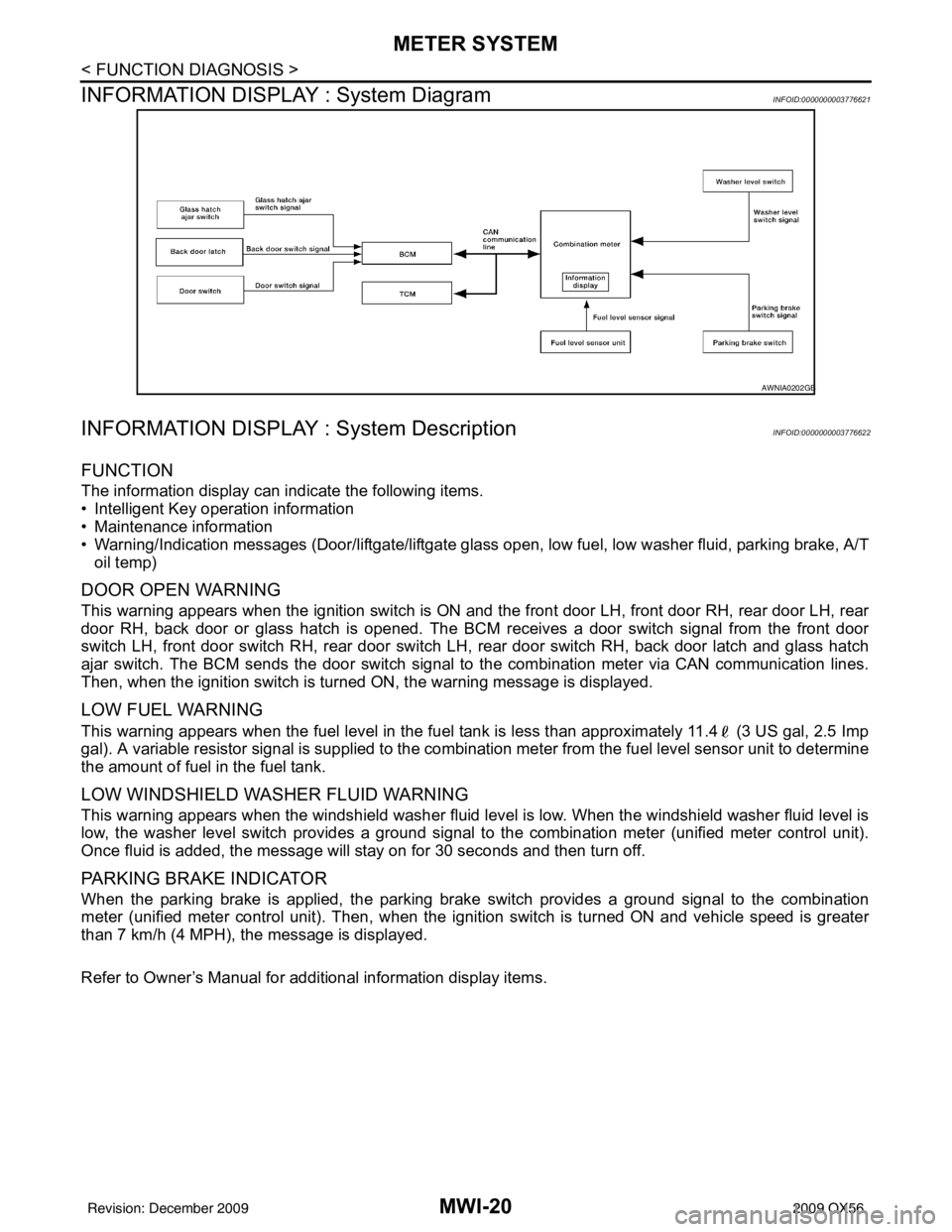
INFORMATION DISPLAY : System Diagram
INFOID:0000000003776621
INFORMATION DISPLAY : System DescriptionINFOID:0000000003776622
FUNCTION
The information display can indicate the following items.
• Intelligent Key operation information
• Maintenance information
• Warning/Indication messages (Door/liftgate/liftgate glass open, low fuel, low washer fluid, parking brake, A/T
oil temp)
DOOR OPEN WARNING
This warning appears when the ignition switch is ON and the front door LH, front door RH, rear door LH, rear
door RH, back door or glass hatch is opened. The BCM receives a door switch signal from the front door
switch LH, front door switch RH, rear door switch LH, rear door switch RH, back door latch and glass hatch
ajar switch. The BCM sends the door switch signal to the combination meter via CAN communication lines.
Then, when the ignition switch is turned ON, the warning message is displayed.
LOW FUEL WARNING
This warning appears when the fuel level in the fuel tank is less than approximately 11.4 (3 US gal, 2.5 Imp
gal). A variable resistor signal is supplied to the combination meter from the fuel level sensor unit to determine
the amount of fuel in the fuel tank.
LOW WINDSHIELD WASHER FLUID WARNING
This warning appears when the windshield washer fluid level is low. When the windshield washer fluid level is
low, the washer level switch provides a ground signal to the combination meter (unified meter control unit).
Once fluid is added, the message will stay on for 30 seconds and then turn off.
PARKING BRAKE INDICATOR
When the parking brake is applied, the parking brake switch provides a ground signal to the combination
meter (unified meter control unit). Then, when the igni tion switch is turned ON and vehicle speed is greater
than 7 km/h (4 MPH), the message is displayed.
Refer to Owner’s Manual for additional information display items.
AWNIA0202GB
Revision: December 20092009 QX56
Page 2743 of 4171
MWI
METER SYSTEMMWI-21
< FUNCTION DIAGNOSIS >
C
DE
F
G H
I
J
K L
M B A
O P
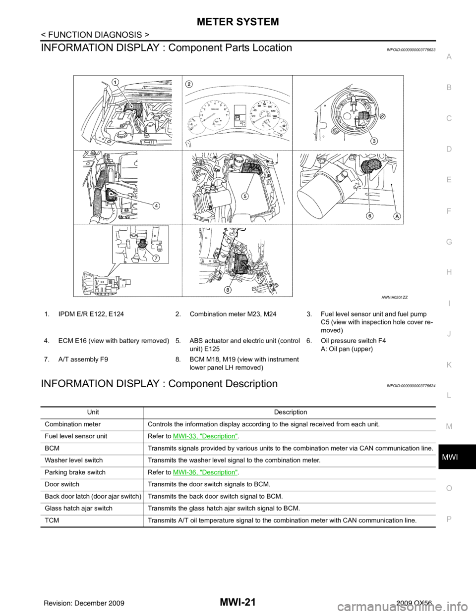
INFORMATION DISPLAY : Co mponent Parts LocationINFOID:0000000003776623
INFORMATION DISPLAY : Component DescriptionINFOID:0000000003776624
1. IPDM E/R E122, E124 2. Combination meter M23, M24 3. Fuel level sensor unit and fuel pump
C5 (view with inspection hole cover re-
moved)
4. ECM E16 (view with battery removed) 5. ABS actuator and electric unit (control unit) E1256. Oil pressure switch F4
A: Oil pan (upper)
7. A/T assembly F9 8. BCM M18, M19 (view with instrument
lower panel LH removed)
AWNIA0201ZZ
Unit Description
Combination meter Controls the information display according to the signal received from each unit.
Fuel level sensor unit Refer to MWI-33, "
Description".
BCM Transmits signals provided by various units to the combination meter via CAN communication line.
Washer level switch Transmits the washer level signal to the combination meter.
Parking brake switch Refer to MWI-36, "
Description".
Door switch Transmits the door switch signals to BCM.
Back door latch (door ajar switch) Transmits the back door switch signal to BCM.
Glass hatch ajar switch Transmits the glass hatch ajar switch signal to BCM.
TCM Transmits A/T oil temperature signal to the combination meter with CAN communication line.
Revision: December 20092009 QX56
Page 2755 of 4171
MWI
FUEL LEVEL SENSOR SIGNAL CIRCUITMWI-33
< COMPONENT DIAGNOSIS >
C
DE
F
G H
I
J
K L
M B A
O P
FUEL LEVEL SENSOR SIGNAL CIRCUIT
DescriptionINFOID:0000000003776636
The fuel level sensor unit and fuel pump detects the approx imate fuel level in the fuel tank and transmits the
fuel level signal to the combination meter.
Component Function CheckINFOID:0000000003776637
1.COMBINATION METER INPUT SIGNAL
1. Select “METER/M&A” on CONSULT-III.
2. Using “FUEL METER” of “DATA MONITOR”, comp are the value of DATA MONITOR with fuel gauge
pointer of combination meter.
Does the data monitor value approximately match the fuel gauge indication?
YES >> Inspection End.
NO >> Replace combination meter. Refer to MWI-102, "
Removal and Installation".
Diagnosis ProcedureINFOID:0000000003776638
1.CHECK HARNESS CONNECTOR
1. Turn ignition switch OFF.
2. Check combination meter and fuel level sensor unit terminals (meter-side and harness-side) for poor con- nection.
Is the inspection result normal?
YES >> GO TO 2
NO >> Repair or replace terminals or connectors.
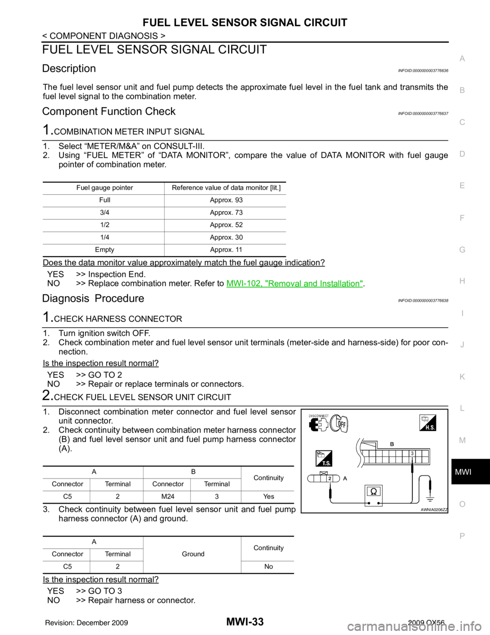
2.CHECK FUEL LEVEL SENSOR UNIT CIRCUIT
1. Disconnect combination meter connector and fuel level sensor unit connector.
2. Check continuity between combination meter harness connector
(B) and fuel level sensor unit and fuel pump harness connector
(A).
3. Check continuity between fuel level sensor unit and fuel pump harness connector (A) and ground.
Is the inspection result normal?
YES >> GO TO 3
NO >> Repair harness or connector.
Fuel gauge pointer Reference value of data monitor [lit.]
Full Approx. 93
3/4 Approx. 73
1/2 Approx. 52
1/4 Approx. 30
Empty Approx. 11
AB
Continuity
Connector Terminal Connector Terminal
C5 2 M24 3 Yes
A GroundContinuity
Connector Terminal
C5 2 No
AWNIA0206ZZ
Revision: December 20092009 QX56
Page 2756 of 4171

MWI-34
< COMPONENT DIAGNOSIS >
FUEL LEVEL SENSOR SIGNAL CIRCUIT
3.CHECK FUEL LEVEL SENSOR UNIT GROUND CIRCUIT
1. Check continuity between combination meter harness connector (B) and fuel level sensor uni t and fuel pump harness connector
(A).
2. Check continuity between fuel level sensor unit and fuel pump harness connector (A) and ground.
Is the inspection result normal?
YES >> GO TO 4
NO >> Repair harness or connector.
4.CHECK INSTALLATION CONDITION
Check fuel level sensor unit installation, and check whether the float arm interferes or binds with any of the
internal components in the fuel tank.
Is the inspection result normal?
YES >> Inspection End.
NO >> Install the fuel level sensor unit properly.
Component InspectionINFOID:0000000003776639
1.REMOVE FUEL LEVEL SENSOR UNIT
Remove the fuel level sensor unit. Refer to FL-7, "
Removal and Installation".
>> GO TO 2
2.CHECK FUEL LEVEL SENSOR UNIT AND FUEL PUMP
Check the resistance between terminals 2 and 5.
*1 and *2: When float arm is in contact with stopper.
Is inspection result normal?
YES >> Inspection End.
NO >> Replace fuel level sensor unit and fuel pump. Refer to FL-7, "
Removal and Installation".
AB Continuity
Connector Terminal Connector Terminal
C5 5 M24 4 Yes
A GroundContinuity
Connector Terminal
C5 5 No
AWNIA0207ZZ
Te r m i n a l Float position
mm (in) Resistance value
(Approx.)
25 *1 Empty
7.5 (0.3)80Ω
*2 Full 218.9 (8.6)6Ω
LKIA0402E
Revision: December 20092009 QX56
Page 2764 of 4171
MWI-42
< ECU DIAGNOSIS >
COMBINATION METER
ECU DIAGNOSIS
COMBINATION METER
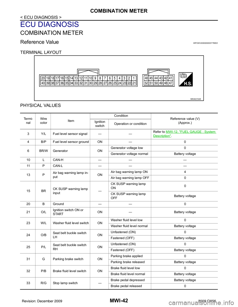
Reference ValueINFOID:0000000003776653
TERMINAL LAYOUT
PHYSICAL VALUES
WKIA5724E
Te r m i -nal Wire
color Item Condition
Reference value (V)
(Approx.)
Ignition
switch Operation or condition
3 Y/L Fuel level sensor signal — —Refer to MWI-12, "
FUEL GAUGE : System
Description".
4 B/P Fuel level sensor ground ON —0
6 BR/W Generator ONGenerator voltage low
0
Generator voltage normal Battery voltage
10 L CAN-H —— —
11 P C A N - L —— —
13 P Air bag warning lamp in-
put ONAir bag warning lamp ON
4
Air bag warning lamp OFF 0
15 BR CK SUSP warning lamp
input —CK SUSP warning lamp
ON
0
CK SUSP warning lamp
OFF Battery voltage
20 B Ground —— 0
21 O/L Ignition switch ON or
START ON
— Battery voltage
23 W/L Washer fluid level switch ON Washer fluid level low
0
Washer fluid level normal Battery voltage
24 O/B Seat belt buckle switch
LH ONUnfastened (ON)
0
Fastened (OFF) Battery voltage
25 P/L Seat belt buckle switch
RH ONUnfastened (ON)
0
Fastened (OFF) Battery voltage
31 G Parking brake switch ON Parking brake applied
0
Parking brake released Battery voltage
32 P/B Brake fluid level switch ON Brake fluid level low
0
Brake fluid level normal Battery voltage
33 R/G Stop lamp switch —Brake pedal depressed
Battery voltage
Brake pedal released 0
Revision: December 20092009 QX56
Page 2789 of 4171
MWI
BCM (BODY CONTROL MODULE)MWI-67
< ECU DIAGNOSIS >
C
DE
F
G H
I
J
K L
M B A
O P
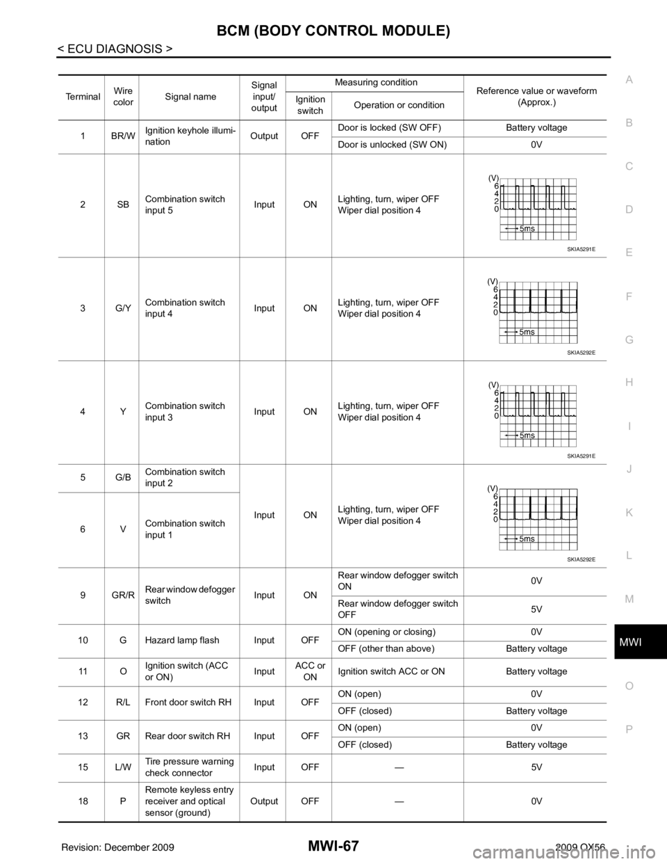
Te r m i n a l Wire
color Signal name Signal
input/
output Measuring condition
Reference value or waveform
(Approx.)
Ignition
switch Operation or condition
1BR/W Ignition keyhole illumi-
nation Output OFFDoor is locked (SW OFF)
Battery voltage
Door is unlocked (SW ON) 0V
2SB Combination switch
input 5 Input ON
Lighting, turn, wiper OFF
Wiper dial position 4
3G/Y Combination switch
input 4 Input ONLighting, turn, wiper OFF
Wiper dial position 4
4Y Combination switch
input 3 Input ON
Lighting, turn, wiper OFF
Wiper dial position 4
5G/B Combination switch
input 2
Input ONLighting, turn, wiper OFF
Wiper dial position 4
6V Combination switch
input 1
9GR/R Rear window defogger
switch
Input ONRear window defogger switch
ON
0V
Rear window defogger switch
OFF 5V
10 G Hazard lamp flash Input OFF ON (opening or closing)
0V
OFF (other than above) Battery voltage
11 O Ignition switch (ACC
or ON)
InputACC or
ON Ignition switch ACC or ON
Battery voltage
12 R/L Front door switch RH Input OFF ON (open)
0V
OFF (closed) Battery voltage
13 GR Rear door switch RH Input OFF ON (open)
0V
OFF (closed) Battery voltage
15 L/W Tire pressure warning
check connector
Input OFF
—5V
18 P Remote keyless entry
receiver and optical
sensor (ground)
Output OFF
—0V
SKIA5291E
SKIA5292E
SKIA5291E
SKIA5292E
Revision: December 20092009 QX56
Page 2793 of 4171
MWI
BCM (BODY CONTROL MODULE)MWI-71
< ECU DIAGNOSIS >
C
DE
F
G H
I
J
K L
M B A
O P
58 W/R Optical sensor Input ONWhen optical sensor is illumi-
nated
3.1V or more
When optical sensor is not illu-
minated 0.6V or less
59 G Front door lock as-
sembly LH actuator
(unlock) Output OFF
OFF (neutral)
0V
ON (unlock) Battery voltage
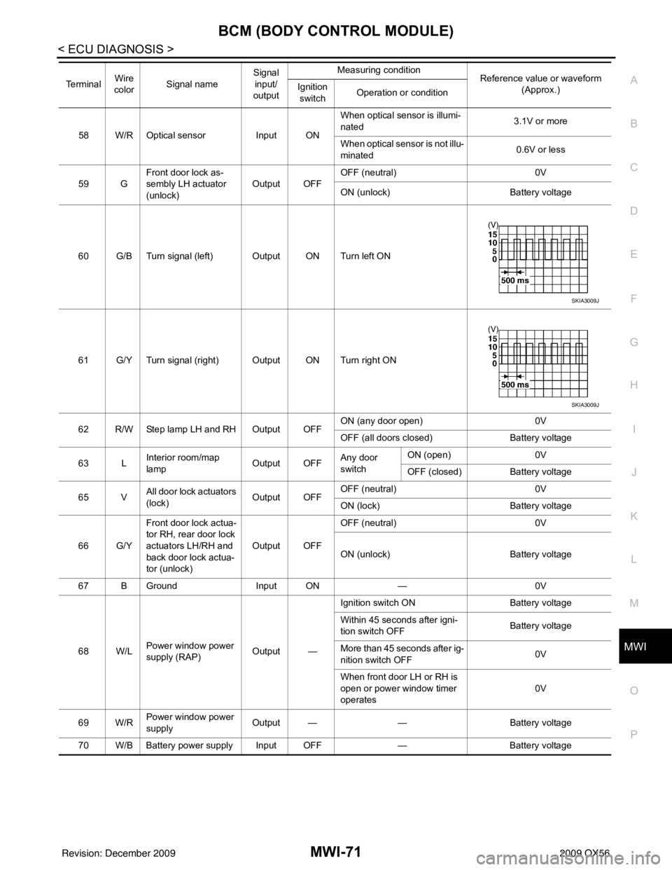
60 G/B Turn signal (left) Output ON Turn left ON
61 G/Y Turn signal (right) Output ON Turn right ON
62 R/W Step lamp LH and RH Output OFF ON (any door open)
0V
OFF (all doors closed) Battery voltage
63 L Interior room/map
lamp Output OFFAny door
switchON (open)
0V
OFF (closed) Battery voltage
65 V All door lock actuators
(lock) Output OFFOFF (neutral)
0V
ON (lock) Battery voltage
66 G/Y Front door lock actua-
tor RH, rear door lock
actuators LH/RH and
back door lock actua-
tor (unlock) Output OFF
OFF (neutral)
0V
ON (unlock) Battery voltage
67 B Ground Input ON—0V
68 W/L Power window power
supply (RAP) Output —Ignition switch ON
Battery voltage
Within 45 seconds after igni-
tion switch OFF Battery voltage
More than 45 seconds after ig-
nition switch OFF 0V
When front door LH or RH is
open or power window timer
operates 0V
69 W/R Power window power
supply
Output —
—Battery voltage
70 W/B Battery power supply Input OFF —Battery voltage
Te r m i n a l
Wire
color Signal name Signal
input/
output Measuring condition
Reference value or waveform
(Approx.)
Ignition
switch Operation or condition
SKIA3009J
SKIA3009J
Revision: December 20092009 QX56
Page 2814 of 4171
MWI-92
< SYMPTOM DIAGNOSIS >
THE FUEL GAUGE POINTER DOES NOT MOVE
SYMPTOM DIAGNOSIS
THE FUEL GAUGE POINTER DOES NOT MOVE
DescriptionINFOID:0000000003776669
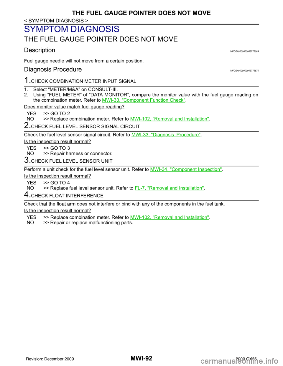
Fuel gauge needle will not move from a certain position.
Diagnosis ProcedureINFOID:0000000003776670
1.CHECK COMBINATION METER INPUT SIGNAL
1. Select “METER/M&A” on CONSULT-III.
2. Using “FUEL METER” of “DATA MONITOR”, comp are the monitor value with the fuel gauge reading on
the combination meter. Refer to MWI-33, "
Component Function Check".
Does monitor value match fuel gauge reading?
YES >> GO TO 2
NO >> Replace combination meter. Refer to MWI-102, "
Removal and Installation".
2.CHECK FUEL LEVEL SENSOR SIGNAL CIRCUIT
Check the fuel level sensor signal circuit. Refer to MWI-33, "
DiagnosisProcedure".
Is the inspection result normal?
YES >> GO TO 3
NO >> Repair harness or connector.
3.CHECK FUEL LEVEL SENSOR UNIT
Perform a unit check for the fuel level sensor unit. Refer to MWI-34, "
Component Inspection".
Is the inspection result normal?
YES >> GO TO 4
NO >> Replace fuel level sensor unit. Refer to FL-7, "
Removal and Installation".
4.CHECK FLOAT INTERFERENCE
Check that the float arm does not interfere or bi nd with any of the components in the fuel tank.
Is the inspection result normal?
YES >> Replace combination meter. Refer to MWI-102, "Removal and Installation".
NO >> Repair or replace malfunctioning parts.
Revision: December 20092009 QX56