2009 INFINITI QX56 sensor
[x] Cancel search: sensorPage 2271 of 4171
PRECAUTIONSHA-7
< PRECAUTION >
C
DE
F
G H
J
K L
M A
B
HA
N
O P
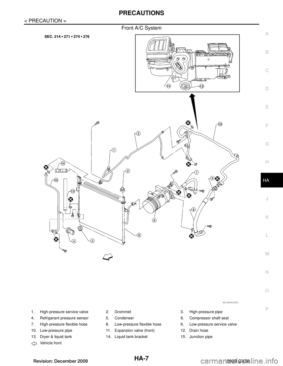
Front A/C System
ALIIA0402ZZ
1. High-pressure service valve 2 . Grommet 3. High-pressure pipe
4. Refrigerant pressure sensor 5. Condenser 6. Compressor shaft seal
7. High-pressure flexible hose 8. Low-pressure flexible hose 9. Low-pressure service valve
10. Low-pressure pipe 11. Expansion valve (front) 12. Drain hose
13. Dryer & liquid tank 14. Liquid tank bracket 15. Junction pipe Vehicle front
Revision: December 20092009 QX56
Page 2281 of 4171

REFRIGERATION SYSTEMHA-17
< FUNCTION DIAGNOSIS >
C
DE
F
G H
J
K L
M A
B
HA
N
O P
FUNCTION DIAGNOSIS
REFRIGERATION SYSTEM
Refrigerant CycleINFOID:0000000003775298
REFRIGERANT FLOW
The refrigerant flows in the standard pattern, that is , through the compressor, the condenser with liquid tank,
through the front and rear evaporators, and back to the compressor. The refrigerant evaporation through the
evaporator coils are controlled by fr ont and rear externally equalized expansion valves, located inside the front
and rear evaporator cases.
Refrigerant System ProtectionINFOID:0000000003775299
REFRIGERANT PRESSURE SENSOR
The refrigerant system is protected against excessively hi gh or low pressures by the refrigerant pressure sen-
sor, located on the condenser. If the system pressure rise s above or falls below the specifications, the refriger-
ant pressure sensor detects the pressure inside the refrigerant line and sends a voltage signal to the ECM.
The ECM de-energizes the A/C relay to disengage the magnet ic compressor clutch when pressure on the high
pressure side detected by refrigerant pressu re sensor is over about 2,746 kPa (28 kg/cm
2, 398 psi), or below
about 120 kPa (1.22 kg/cm
2, 17.4 psi).
PRESSURE RELIEF VALVE
The refrigerant system is also protected by a pressure relief valve, located in the rear head of the compressor.
When the pressure of refrigerant in the system incr eases to an abnormal level [more than 2,990 kPa (30.5 kg/
Revision: December 20092009 QX56
Page 2288 of 4171

HA-24
< ON-VEHICLE MAINTENANCE >
FLUORESCENT LEAK DETECTOR
FLUORESCENT LEAK DETECTOR
Checking of Refrigerant LeaksINFOID:0000000003775303
PRELIMINARY CHECK
Perform a visual inspection of all refrigeration parts, fittings, hoses and components for signs of A/C oil leak-
age, damage, and corrosion. Any A/C oil leakage may indicate an area of refrigerant leakage. Allow extra
inspection time in these areas when using either an el ectronic refrigerant leak detector (J-41995) or fluores-
cent dye leak detector (J-42220).
If any dye is observed using a fluor escent dye leak detector (J-42220), c onfirm the leak using a electronic
refrigerant leak detector (J-41995). It is possible that the dye is from a prior leak that was repaired and not
properly cleaned.
When searching for leaks, do not stop when one leak is found but continue to check for additional leaks at all
system components and connections.
When searching for refrigerant leaks using an electroni c refrigerant leak detector (J-41995), move the probe
along the suspected leak area at 25 - 50 mm (1 - 2 in) per second and no further than 6 mm (1/4 in) from the
component.
CAUTION:
Moving the electronic refrigerant l eak detector probe slower and clo ser to the suspected leak area will
improve the chances of finding a leak.
Checking System for L eaks Using the Fluorescent Dye Leak DetectorINFOID:0000000003775304
1. Check the A/C system for leaks using the fluorescent dye leak detector and safety goggles (J-42220) in a
low sunlight area (area without windows preferable). Il luminate all components, fittings and lines. The dye
will appear as a bright green/yellow area at the point of leakage. Fluorescent dye observed at the evapo-
rator drain opening indicates an evaporator core asse mbly leak (tubes, core or expansion valve).
2. If the suspected area is difficult to see, use an adjustable mirror or wipe the area with a clean shop rag or
cloth, then inspect the shop rag or cloth with the fl uorescent dye leak detector (J-42220) for dye residue.
3. After the leak is repaired, remove any residual dye using refrigerant dye cleaner (J-43872) to prevent
future misdiagnosis.
4. Perform a system performance check and then verify t he leak repair using a electronic refrigerant leak
detector (J-41995).
NOTE:
Other gases in the work area or substances on the A/C components, for example, anti-freeze, wind-
shield washer fluid, solvents and oils, may falsely tri gger the leak detector. Make sure the surfaces to be
checked are clean.
Clean with a dry cloth or blow off with shop air.
Do not allow the sensor tip of the electronic refri gerant leak detector (J-41995) to contact with any sub-
stance. This can also cause false readings and may damage the detector.
Dye InjectionINFOID:0000000003775305
NOTE:
This procedure is only necessary when recharging t he system or when the compressor has seized and must
be replaced.
1. Check the A/C system static (at rest) pressure . Pressure must be at least 345 kPa (3.52 kg/cm
2 , 50 psi).
2. Pour one bottle 7.4 cc (1/4 ounce) of the HFC-134a (R -134a) fluorescent leak detection dye (J-41447) into
the HFC-134a (R-134a) dye injector (J-41459).
CAUTION:
If repairing the A/C system or replacing a co mponent, pour the HFC-134a (R-134a) fluorescent leak
detection dye (J-41447) directly into the open system connection and proceed with the service
procedures.
3. Connect the refrigerant dye injector (J- 41459) to the low-pressure service valve.
4. Start the engine and switch the A/C system ON.
5. When the A/C system is operating (compressor runni ng), inject one bottle 7.4 cc (1/4 ounce) of HFC-134a
(R-134a) fluorescent leak detection dye (J-41447) th rough the low-pressure service valve using HFC-
134a (R-134a) dye injector (J-41459). Refer to the manufacturer's operating instructions.
Revision: December 20092009 QX56
Page 2291 of 4171
ELECTRICAL LEAK DETECTORHA-27
< ON-VEHICLE MAINTENANCE >
C
DE
F
G H
J
K L
M A
B
HA
N
O P
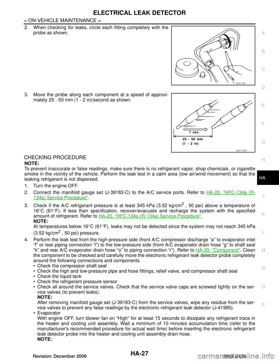
2. When checking for leaks, circle each fitting completely with the probe as shown.
3. Move the probe along each component at a speed of approxi- mately 25 - 50 mm (1 - 2 in)/second as shown.
CHECKING PROCEDURE
NOTE:
To prevent inaccurate or false readings, make sure t here is no refrigerant vapor, shop chemicals, or cigarette
smoke in the vicinity of the vehicle. Perform the leak test in a calm area (low air/wind movement) so that the
leaking refrigerant is not dispersed.
1. Turn the engine OFF.
2. Connect the manifold gauge set (J-39183-C) to the A/C service ports. Refer to HA-20, "HFC-134a (R-
134a) Service Procedure".
3. Check if the A/C refrigerant pressu re is at least 345 kPa (3.52 kg/cm
2 , 50 psi) above a temperature of
16 °C (61 °F). If less than specification, recover/ev acuate and recharge the system with the specified
amount of refrigerant. Refer to HA-20, "HFC-134a (R-134a) Service Procedure"
.
NOTE:
At temperatures below 16 °C (61 °F), leaks may not be detected sinc e the system may not reach 345 kPa
(3.52 kg/cm
2 , 50 psi) pressure.
4. Perform the leak test from the high-pressure side (f ront A/C compressor discharge “a” to evaporator inlet
“f” or rear piping connection “l”) to the low-pressure side (front A/C evaporator drain hose “g” to shaft seal
“k” and rear A/C evaporator drain hose “o” to piping connection “r”). Refer to HA-29, "Component"
. Clean
the component to be checked and carefully move the electronic refrigerant leak detector probe completely
around the following connections and components.
Check the compressor shaft seal
Check the high and low-pressure pipe and hose fitt ings, relief valve, and compressor shaft seal
Check the liquid tank
Check the refrigerant pressure sensor
Check all around the service valves. Check that the service valve caps are screwed tightly on the ser-
vice valves (to prevent leaks).
NOTE:
After removing manifold gauge set (J-39183-C) from t he service valves, wipe any residue from the ser-
vice valves to prevent any false readings by the electronic refrigerant leak detector (J-41995).
Evaporator
With engine OFF, turn blower fan on “High” for at least 15 seconds to dissipate any refrigerant trace in
the heater and cooling unit assembly. Wait a minimum of 10 minutes accumulation time (refer to the
manufacturer's recommended procedure for actual wait time) before inserting the electronic refrigerant
leak detector probe into the heater and cooling unit assembly drain hose.
NOTE:
SHA706E
SHA708EA
Revision: December 20092009 QX56
Page 2294 of 4171
HA-30
< ON-VEHICLE REPAIR >
REFRIGERATION SYSTEM
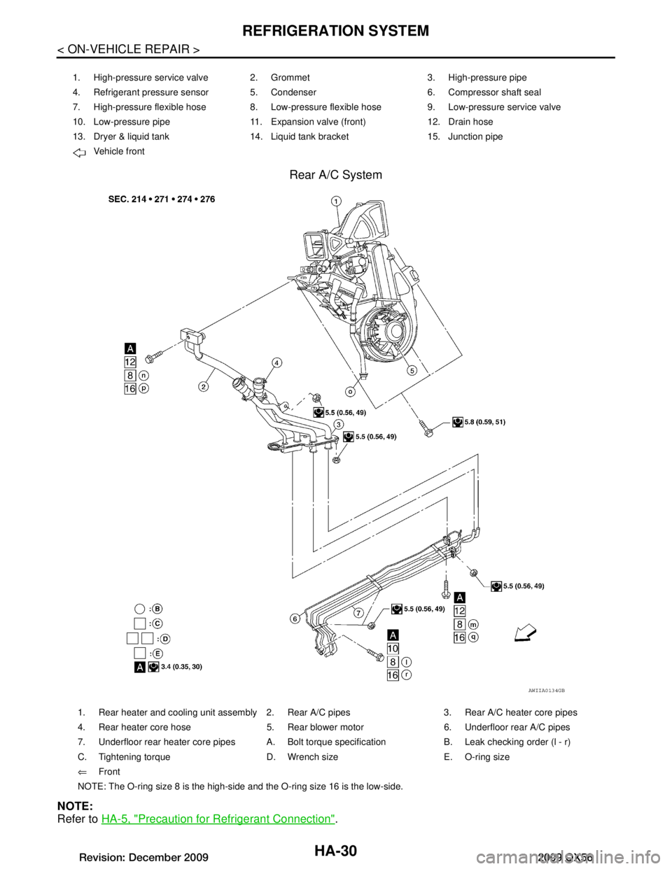
Rear A/C System
NOTE:
Refer to HA-5, "Precaution for Refrigerant Connection"
.
1. High-pressure service valve 2. Grommet 3. High-pressure pipe
4. Refrigerant pressure sensor 5. Condenser 6. Compressor shaft seal
7. High-pressure flexible hose 8. Low-pressure flexible hose 9. Low-pressure service valve
10. Low-pressure pipe 11. Expansion valve (front) 12. Drain hose
13. Dryer & liquid tank 14. Liquid tank bracket 15. Junction pipe
Vehicle front
AWIIA0134GB
1. Rear heater and cooling unit assembly 2. Rear A/C pipes 3. Rear A/C heater core pipes
4. Rear heater core hose 5. Rear blower motor 6. Underfloor rear A/C pipes
7. Underfloor rear heater core pipes A. Bolt torque specification B. Leak checking order (l - r)
C. Tightening torque D. Wrench size E. O-ring size
⇐Front
NOTE: The O-ring size 8 is the high-side and the O-ring size 16 is the low-side.
Revision: December 20092009 QX56
Page 2308 of 4171
HA-44
< ON-VEHICLE REPAIR >
CONDENSER
CONDENSER
Removal and Installation for CondenserINFOID:0000000003775319
REMOVAL
1. Discharge the refrigerant. Refer to HA-20, "HFC-134a (R-134a) Service Procedure".
2. Remove the radiator. Refer to CO-15, "Removal and Installation"
.
CAUTION:
Be careful not to damage the core su rface of the condenser and the radiator.
3. Disconnect the high-pressure flexible hose and the high-pressure pipe from the condenser.
CAUTION:
Cap or wrap the joint of the pipe with suitable ma terial such as vinyl tape to avoid the entry of air.
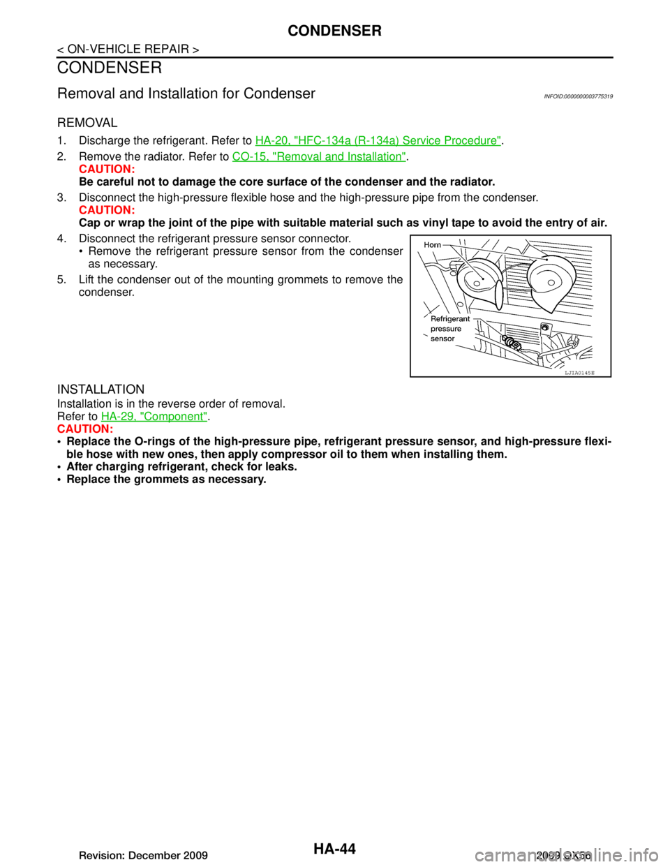
4. Disconnect the refrigerant pressure sensor connector. Remove the refrigerant pressure sensor from the condenseras necessary.
5. Lift the condenser out of the mounting grommets to remove the condenser.
INSTALLATION
Installation is in the reverse order of removal.
Refer to HA-29, "Component"
.
CAUTION:
Replace the O-rings of the high-p ressure pipe, refrigerant pressure sensor, and high-pressure flexi-
ble hose with new ones, then apply compr essor oil to them when installing them.
After charging refrigerant, check for leaks.
Replace the grommets as necessary.
LJIA0145E
Revision: December 20092009 QX56
Page 2309 of 4171
AMBIENT SENSORHA-45
< ON-VEHICLE REPAIR >
C
DE
F
G H
J
K L
M A
B
HA
N
O P
AMBIENT SENSOR
Removal and InstallationINFOID:0000000003775320
REMOVAL
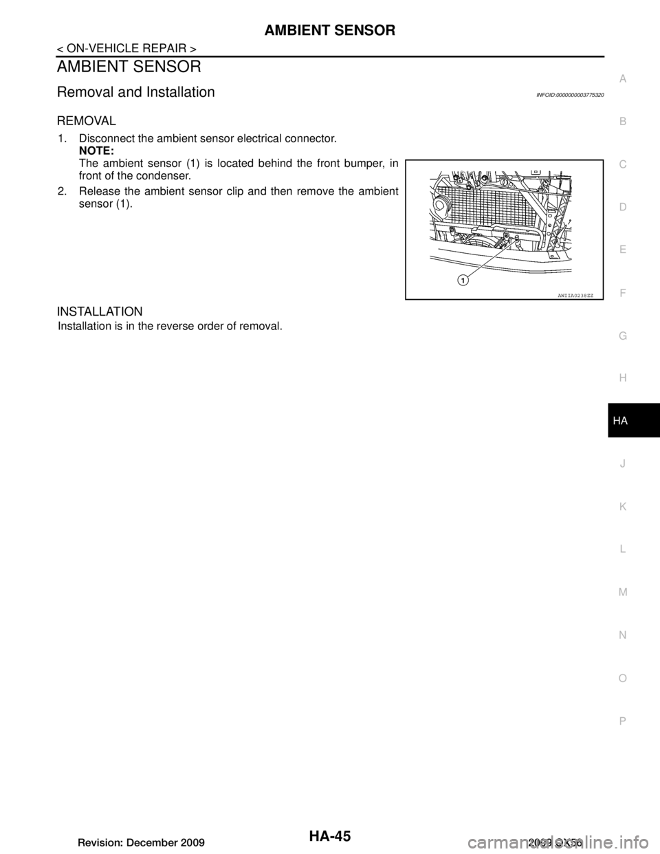
1. Disconnect the ambient sensor electrical connector. NOTE:
The ambient sensor (1) is located behind the front bumper, in
front of the condenser.
2. Release the ambient sensor clip and then remove the ambient sensor (1).
INSTALLATION
Installation is in the reverse order of removal.
AWIIA0238ZZ
Revision: December 20092009 QX56
Page 2310 of 4171
HA-46
< ON-VEHICLE REPAIR >
REFRIGERANT PRESSURE SENSOR
REFRIGERANT PRESSURE SENSOR
Removal and Installation for Refrigerant Pressure SensorINFOID:0000000003775321
REMOVAL
1. Discharge the refrigerant. Refer to HA-20, "HFC-134a (R-134a) Service Procedure".
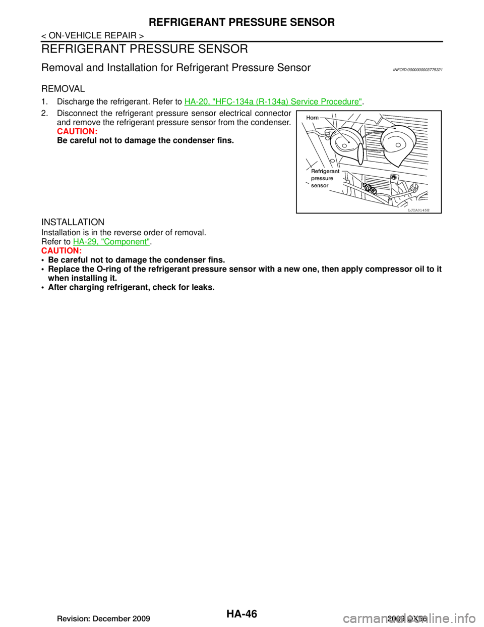
2. Disconnect the refrigerant pressu re sensor electrical connector
and remove the refrigerant pressure sensor from the condenser.
CAUTION:
Be careful not to damage the condenser fins.
INSTALLATION
Installation is in the reverse order of removal.
Refer to HA-29, "Component"
.
CAUTION:
Be careful not to damage the condenser fins.
Replace the O-ring of the refriger ant pressure sensor with a new one, then apply compressor oil to it
when installing it.
After charging refrigerant, check for leaks.
LJIA0145E
Revision: December 20092009 QX56