2009 INFINITI QX56 sensor
[x] Cancel search: sensorPage 2218 of 4171
GI-24
< PRECAUTION >
PRECAUTIONS
PRECAUTION
PRECAUTIONS
DescriptionINFOID:0000000003771195
Observe the following precautions to ensure safe and proper servicing. These precautions are not
described in each individual section.
Precaution for Supplemental Restraint Syst em (SRS) "AIR BAG" and "SEAT BELT
PRE-TENSIONER"
INFOID:0000000005867503
The Supplemental Restraint System such as “A IR BAG” and “SEAT BELT PRE-TENSIONER”, used along
with a front seat belt, helps to reduce the risk or severity of injury to the driver and front passenger for certain
types of collision. This system includes seat belt switch inputs and dual stage front air bag modules. The SRS
system uses the seat belt switches to determine the front air bag deployment, and may only deploy one front
air bag, depending on the severity of a collision and w hether the front occupants are belted or unbelted.
Information necessary to service the system safely is included in the SR and SB section of this Service Man-
ual.
WARNING:
• To avoid rendering the SRS inopera tive, which could increase the risk of personal injury or death in
the event of a collision which would result in air bag inflation, all maintenance must be performed by
an authorized NISSAN/INFINITI dealer.
• Improper maintenance, including in correct removal and installation of the SRS, can lead to personal
injury caused by unintent ional activation of the system. For re moval of Spiral Cable and Air Bag
Module, see the SR section.
• Do not use electrical test equipmen t on any circuit related to the SRS unless instructed to in this
Service Manual. SRS wiring harn esses can be identified by yellow and/or orange harnesses or har-
ness connectors.
PRECAUTIONS WHEN USING POWER TOOLS (AIR OR ELECTRIC) AND HAMMERS
WARNING:
• When working near the Airbag Diagnosis Sensor Unit or other Airbag System sensors with the Igni-
tion ON or engine running, DO NOT use air or electri c power tools or strike near the sensor(s) with a
hammer. Heavy vibration could activate the sensor( s) and deploy the air bag(s), possibly causing
serious injury.
• When using air or electric power tools or hammers , always switch the Ignition OFF, disconnect the
battery, and wait at least 3 minu tes before performing any service.
Precaution Necessary for Steering W heel Rotation After Battery Disconnect
INFOID:0000000005892330
NOTE:
• This Procedure is applied only to models with Intelligent Key system and NATS (NISSAN ANTI-THEFT SYS-
TEM).
• Remove and install all control units after disconnecting both battery cables with the ignition knob in the
″LOCK ″ position.
• Always use CONSULT-III to perform self-diagnosis as a part of each function inspection after finishing work.
If DTC is detected, perform trouble diagnosis according to self-diagnostic results.
For models equipped with the Intelligent Key system and NATS, an electrically controlled steering lock mech-
anism is adopted on the key cylinder.
For this reason, if the battery is disconnected or if the battery is discharged, the steering wheel will lock and
steering wheel rotation will become impossible.
If steering wheel rotation is required when battery pow er is interrupted, follow the procedure below before
starting the repair operation.
OPERATION PROCEDURE
1. Connect both battery cables. NOTE:
Supply power using jumper cables if battery is discharged.
Revision: December 20092009 QX56
Page 2221 of 4171
PRECAUTIONSGI-27
< PRECAUTION >
C
DE
F
G H
I
J
K L
M B
GI
N
O P
system. The connectors should be disconnected only when working according to the WORK FLOW of
TROUBLE DIAGNOSES in EC and TM sections.
Three Way CatalystINFOID:0000000003771200
If a large amount of unburned fuel flows into the catalyst, the catalyst temperature will be excessively high. To
prevent this, follow the instructions.
• Use unleaded gasoline only. Leaded gasoline will seriously damage the three way catalyst.
• When checking for ignition spark or measuring engine compression, make tests quickly and only when nec-
essary.
• Do not run engine when the fuel tank level is low, otherwise the engine may misfire, causing damage to the
catalyst.
Do not place the vehicle on flammable material. Keep flammable material off the exhaust pipe and the three
way catalyst.
Precaution for Fuel (Unlead ed Premium Gasoline Recommended)INFOID:0000000005892332
NISSAN/INFINITI recommends the us e of unleaded premium gasoline with an octane rating of at least 91 AKI
(Anti-Knock Index) number (Research octane number 96). If unleaded premium gasoline is not available,
unleaded regular gasoline with an octane rating of at least 87 AKI number (Research octane number 91), but
you may notice a decrease in performance.
CAUTION:
Do not use leaded gasoline. Usin g leaded gasoline will damage the three way catalyst. Using a fuel
other than that specified could adversely affect the emission cont rol devices and systems, and could
also affect the warranty coverage validity.
CAUTION:
Do not use E-85 fuel in your vehicle. Your vehicle is not designed to run on E-85 fuel. Using E-85 fuel
can cause damage to the fuel system components an d is not covered by the INFINTI vehicle limited
warranty.
Multiport Fuel Inje ction System or Engine Control SystemINFOID:0000000003771202
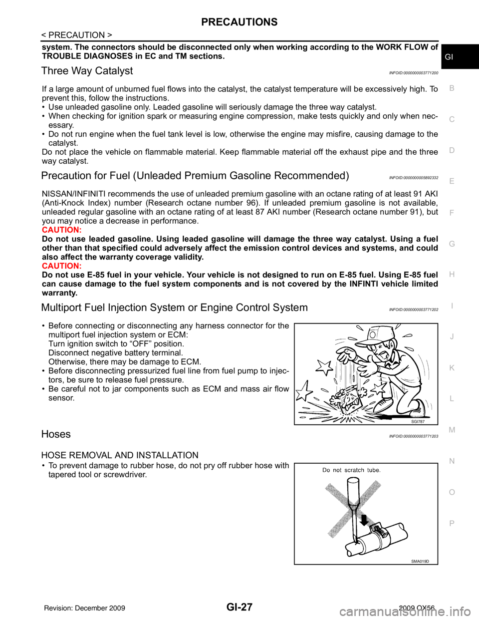
• Before connecting or disconnecting any harness connector for the
multiport fuel injection system or ECM:
Turn ignition switch to “OFF” position.
Disconnect negative battery terminal.
Otherwise, there may be damage to ECM.
• Before disconnecting pressurized fuel line from fuel pump to injec- tors, be sure to release fuel pressure.
• Be careful not to jar components such as ECM and mass air flow sensor.
HosesINFOID:0000000003771203
HOSE REMOVAL AND INSTALLATION
• To prevent damage to rubber hose, do not pry off rubber hose withtapered tool or screwdriver.
SGI787
SMA019D
Revision: December 20092009 QX56
Page 2233 of 4171
SERVICE INFORMATION FOR ELECTRICAL INCIDENTGI-39
< BASIC INSPECTION >
C
DE
F
G H
I
J
K L
M B
GI
N
O P
lowing section illustrates ways to simulate the c onditions/environment under which the owner experiences an
electrical incident.
The section is broken into the six following topics:• Vehicle vibration
• Heat sensitive
• Freezing
• Water intrusion
• Electrical load
• Cold or hot start up
Get a thorough description of the incident from the customer . It is important for simulating the conditions of the
problem.
VEHICLE VIBRATION
The problem may occur or become worse while driving on a rough road or when engine is vibrating (idle with
A/C on). In such a case, you will want to check for a vibration related condition. Refer to the following illustra-
tion.
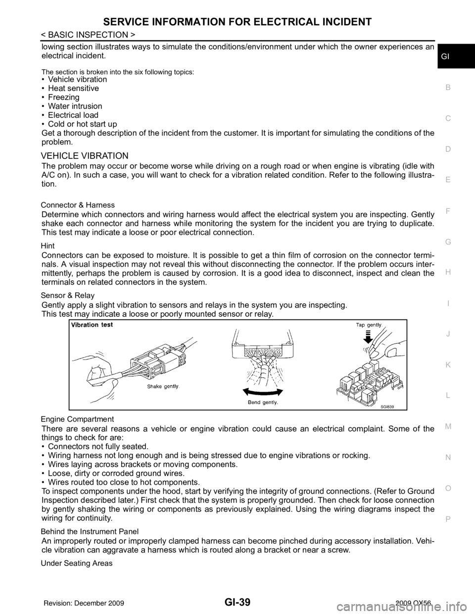
Connector & Harness
Determine which connectors and wiring harness would affect the electrical system you are inspecting. Gently
shake each connector and harness while monitoring the syst em for the incident you are trying to duplicate.
This test may indicate a loose or poor electrical connection.
Hint
Connectors can be exposed to moisture. It is possible to get a thin film of corrosion on the connector termi-
nals. A visual inspection may not reveal this without disconnecting the connector. If the problem occurs inter-
mittently, perhaps the problem is caused by corrosi on. It is a good idea to disconnect, inspect and clean the
terminals on related connectors in the system.
Sensor & Relay
Gently apply a slight vibration to sensors and relays in the system you are inspecting.
This test may indicate a loose or poorly mounted sensor or relay.
Engine Compartment
There are several reasons a vehicle or engine vibration could cause an electrical complaint. Some of the
things to check for are:
• Connectors not fully seated.
• Wiring harness not long enough and is being stressed due to engine vibrations or rocking.
• Wires laying across brackets or moving components.
• Loose, dirty or corroded ground wires.
• Wires routed too close to hot components.
To inspect components under the hood, start by verifyi ng the integrity of ground connections. (Refer to Ground
Inspection described later.) First check that the system is properly grounded. Then check for loose connection
by gently shaking the wiring or components as previous ly explained. Using the wiring diagrams inspect the
wiring for continuity.
Behind the Instrument Panel
An improperly routed or improperly clamped harness can become pinched during accessory installation. Vehi-
cle vibration can aggravate a harness which is routed along a bracket or near a screw.
Under Seating Areas
SGI839
Revision: December 20092009 QX56
Page 2240 of 4171
GI-46
< BASIC INSPECTION >
CONSULT-III CHECKING SYSTEM
CONSULT-III CHECKING SYSTEM
DescriptionINFOID:0000000003771217
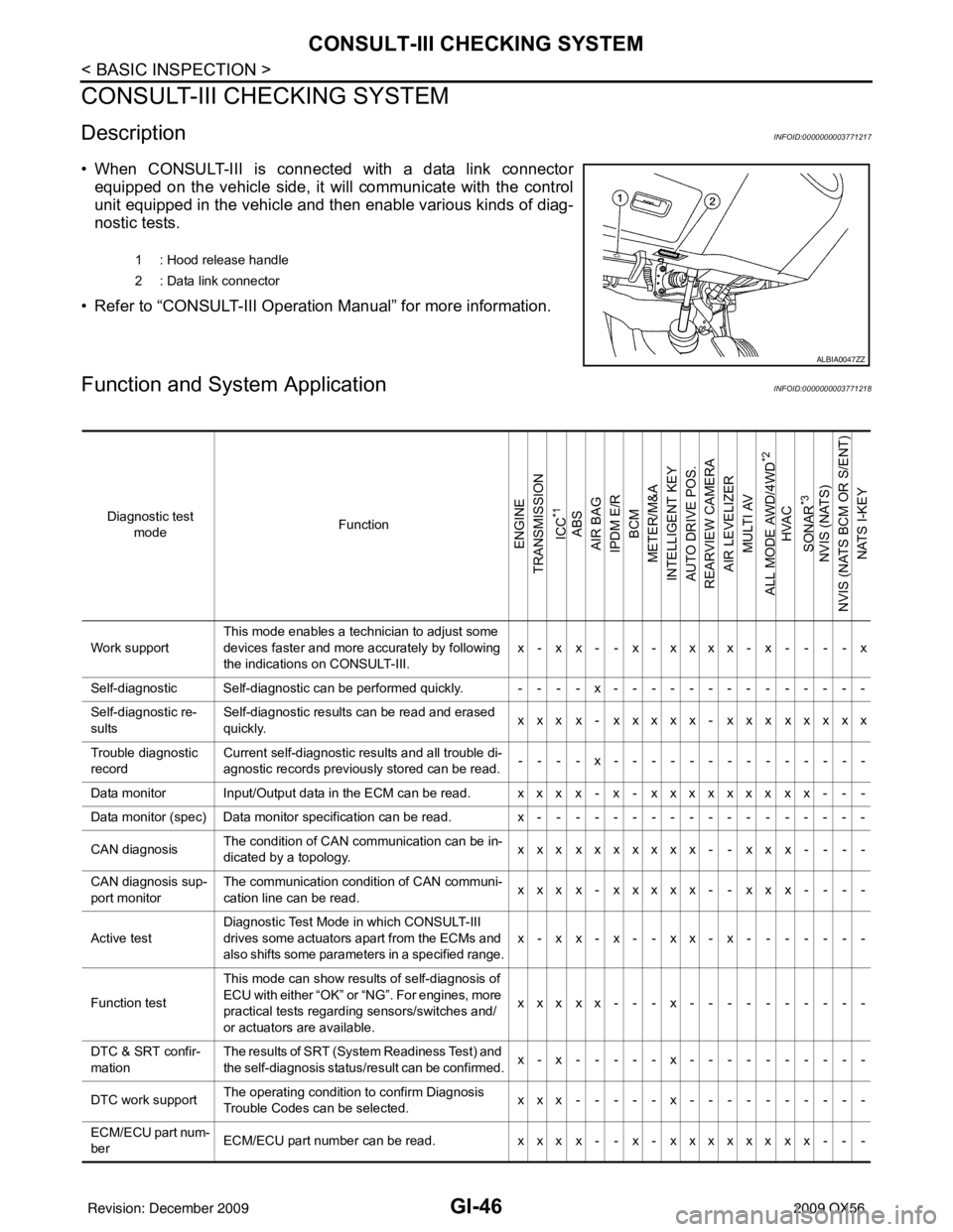
• When CONSULT-III is connected with a data link connectorequipped on the vehicle side, it will communicate with the control
unit equipped in the vehicle and then enable various kinds of diag-
nostic tests.
• Refer to “CONSULT-III Operation Manual” for more information.
Function and System ApplicationINFOID:0000000003771218
1 : Hood release handle
2 : Data link connector
ALBIA0047ZZ
Diagnostic test mode Function
ENGINE
TRANSMISSION
ICC
*1
ABS
AIR BAG
IPDM E/R BCM
METER/M&A
INTELLIGENT KEY
AUTO DRIVE POS.
REARVIEW CAMERA AIR LEVELIZER MULTI AV
ALL MODE AWD/4WD
*2
HVAC
SONAR
*3
NVIS (NATS)
NVIS (NATS BCM OR S/ENT) NATS I-KEY
Work support This mode enables a technician to adjust some
devices faster and more accurately by following
the indications on CONSULT-III. x-xx--x-xxxx-x----x
Self-diagnostic Self-diagnostic can be performed quickly. ----x--------------
Self-diagnostic re-
sults Self-diagnostic results can be read and erased
quickly.
xxx x- xxxxx- xxx xxxxx
Trouble diagnostic
record Current self-diagnostic results and all trouble di-
agnostic records previously stored can be read.
--- - x--- - ----------
Data monitor Input/Output data in the ECM can be read. xxx x- x- xxxxxxx xx- - -
Data monitor (spec) Data monitor specification can be read. x------------------
CAN diagnosis The condition of CAN communication can be in-
dicated by a topology.
xxx xxxxxxx- - xx x- - - -
CAN diagnosis sup-
port monitor The communication condition of CAN communi-
cation line can be read.
xxx x- xxxxx- - xx x- - - -
Active test Diagnostic Test Mode
in which CONSULT-III
drives some actuators apart from the ECMs and
also shifts some parameters in a specified range. x-xx-x--xx-x-------
Function test This mode can show results of self-diagnosis of
ECU with either “OK” or “NG”. For engines, more
practical tests regarding sensors/switches and/
or actuators are available. xxxxx---x----------
DTC & SRT confir-
mation The results of SRT (System Readiness Test) and
the self-diagnosis status/result can be confirmed.
x-x-----x----------
DTC work support The operating condition to confirm Diagnosis
Trouble Codes can be selected. xxx-----x----------
ECM/ECU part num-
ber ECM/ECU part number can be read.
xxx x- - x- xxxxxx xx- - -
Revision: December 20092009 QX56
Page 2250 of 4171
GW-8
< PRECAUTION >
PRECAUTIONS
PRECAUTION
PRECAUTIONS
Precaution for Supplemental Restraint System (SRS) "AIR BAG" and "SEAT BELT
PRE-TENSIONER"
INFOID:0000000005944001
The Supplemental Restraint System such as “A IR BAG” and “SEAT BELT PRE-TENSIONER”, used along
with a front seat belt, helps to reduce the risk or severity of injury to the driver and front passenger for certain
types of collision. This system includes seat belt switch inputs and dual stage front air bag modules. The SRS
system uses the seat belt switches to determine the front air bag deployment, and may only deploy one front
air bag, depending on the severity of a collision and w hether the front occupants are belted or unbelted.
Information necessary to service the system safely is included in the SR and SB section of this Service Man-
ual.
WARNING:
• To avoid rendering the SRS inopera tive, which could increase the risk of personal injury or death in
the event of a collision which would result in air bag inflation, all maintenance must be performed by
an authorized NISSAN/INFINITI dealer.
• Improper maintenance, including in correct removal and installation of the SRS, can lead to personal
injury caused by unintent ional activation of the system. For re moval of Spiral Cable and Air Bag
Module, see the SR section.
• Do not use electrical test equipmen t on any circuit related to the SRS unless instructed to in this
Service Manual. SRS wiring harn esses can be identified by yellow and/or orange harnesses or har-
ness connectors.
PRECAUTIONS WHEN USING POWER TOOLS (AIR OR ELECTRIC) AND HAMMERS
WARNING:
• When working near the Airbag Diagnosis Sensor Unit or other Airbag System sensors with the Igni-
tion ON or engine running, DO NOT use air or electri c power tools or strike near the sensor(s) with a
hammer. Heavy vibration could activate the sensor( s) and deploy the air bag(s), possibly causing
serious injury.
• When using air or electric power tools or hammers , always switch the Ignition OFF, disconnect the
battery, and wait at least 3 minu tes before performing any service.
Precaution Necessary for Steering W heel Rotation After Battery Disconnect
INFOID:0000000005867453
NOTE:
• This Procedure is applied only to models with Intelligent Key system and NATS (NISSAN ANTI-THEFT SYS-
TEM).
• Remove and install all control units after disconnecting both battery cables with the ignition knob in the
″LOCK ″ position.
• Always use CONSULT-III to perform self-diagnosis as a part of each function inspection after finishing work.
If DTC is detected, perform trouble diagnosis according to self-diagnostic results.
For models equipped with the Intelligent Key system and NATS, an electrically controlled steering lock mech-
anism is adopted on the key cylinder.
For this reason, if the battery is disconnected or if the battery is discharged, the steering wheel will lock and
steering wheel rotation will become impossible.
If steering wheel rotation is required when battery pow er is interrupted, follow the procedure below before
starting the repair operation.
OPERATION PROCEDURE
1. Connect both battery cables. NOTE:
Supply power using jumper cables if battery is discharged.
2. Use the Intelligent Key or mechanical key to turn the ignition switch to the ″ACC ″ position. At this time, the
steering lock will be released.
3. Disconnect both battery cables. The steering lock will remain released and the steering wheel can be rotated.
4. Perform the necessary repair operation.
Revision: December 20092009 QX56
Page 2266 of 4171

HA-2
CONDENSER ....................................................44
Removal and Installation for Condenser ............. ...44
AMBIENT SENSOR ...........................................45
Removal and Installation ..................................... ...45
REFRIGERANT PRESSURE SENSOR ............46
Removal and Installation for Refrigerant Pressure
Sensor ................................................................. ...
46
EXPANSION VALVE ...................................... ...47
Removal and Installation for Front Expansion
Valve .................................................................... ...
47
LIQUID TANK ................................................. ...48
Removal and Installation of Liquid Tank .............. ...48
SERVICE DATA AND SPECIFICATIONS
(SDS) ............... ...........................................
49
SERVICE DATA AND SPECIFICATIONS
(SDS) .............................................................. ...
49
Service Data and Specification (SDS) ................. ...49
Revision: December 20092009 QX56
Page 2267 of 4171
PRECAUTIONSHA-3
< PRECAUTION >
C
DE
F
G H
J
K L
M A
B
HA
N
O P
PRECAUTION
PRECAUTIONS
Precaution for Supplemental Restraint System (SRS) "AIR BAG" and "SEAT BELT
PRE-TENSIONER"
INFOID:0000000005856236
The Supplemental Restraint System such as “A IR BAG” and “SEAT BELT PRE-TENSIONER”, used along
with a front seat belt, helps to reduce the risk or severi ty of injury to the driver and front passenger for certain
types of collision. This system includes seat belt switch inputs and dual stage front air bag modules. The SRS
system uses the seat belt switches to determine the front air bag deployment, and may only deploy one front
air bag, depending on the severity of a collision and whether the front occupants are belted or unbelted.
Information necessary to service the system safely is included in the SR and SB section of this Service Man-
ual.
WARNING:
• To avoid rendering the SRS inoper ative, which could increase the risk of personal injury or death in
the event of a collision which would result in air bag inflation, all maintenance must be performed by
an authorized NISSAN/INFINITI dealer.
Improper maintenance, including in correct removal and installation of the SRS, can lead to personal
injury caused by unintentional act ivation of the system. For removal of Spiral Cable and Air Bag
Module, see the SR section.
Do not use electrical test equipm ent on any circuit related to the SRS unless instructed to in this
Service Manual. SRS wiring harnesses can be identi fied by yellow and/or orange harnesses or har-
ness connectors.
PRECAUTIONS WHEN USING POWER TOOLS (AIR OR ELECTRIC) AND HAMMERS
WARNING:
When working near the Airbag Diagnosis Sensor Un it or other Airbag System sensors with the Igni-
tion ON or engine running, DO NOT use air or el ectric power tools or strike near the sensor(s) with a
hammer. Heavy vibration could activate the sensor( s) and deploy the air bag(s), possibly causing
serious injury.
When using air or electric power tools or hammers , always switch the Ignition OFF, disconnect the
battery, and wait at least 3 minutes before performing any service.
Precaution Necessary for Steering Wh eel Rotation After Battery Disconnect
INFOID:0000000005856237
NOTE:
This Procedure is applied only to models with Intelligent Key system and NATS (NISSAN ANTI-THEFT SYS-
TEM).
Remove and install all control units after disconnecti ng both battery cables with the ignition knob in the
″ LOCK ″ position.
Always use CONSULT-III to perform self-diagnosis as a part of each function inspection after finishing work.
If DTC is detected, perform trouble diagnosis according to self-diagnostic results.
For models equipped with the Intelligent Key system and NATS , an electrically controlled steering lock mech-
anism is adopted on the key cylinder.
For this reason, if the battery is disconnected or if the battery is discharged, the steering wheel will lock and
steering wheel rotation will become impossible.
If steering wheel rotation is required when battery pow er is interrupted, follow the procedure below before
starting the repair operation.
OPERATION PROCEDURE
1. Connect both battery cables. NOTE:
Supply power using jumper cables if battery is discharged.
2. Use the Intelligent Key or mechanical key to turn the ignition switch to the ″ACC ″ position. At this time, the
steering lock will be released.
3. Disconnect both battery cables. The steering lock will remain released and the steering wheel can be
rotated.
4. Perform the necessary repair operation.
Revision: December 20092009 QX56
Page 2269 of 4171

PRECAUTIONSHA-5
< PRECAUTION >
C
DE
F
G H
J
K L
M A
B
HA
N
O P
General Refrigerant PrecautionINFOID:0000000003775289
WARNING:
Do not release refrigerant into the air. Use appr oved recovery/recycling equipment to capture the
refrigerant every time an air co nditioning system is discharged.
Always wear eye and hand protection (goggles and gloves) when working with any refrigerant or air
conditioning system.
Do not store or heat refrigerant containers above 52 °C (125 °F).
Do not heat a refrigerant containe r with an open flame; if container warming is required, place the
bottom of the container in a warm pail of water.
Do not intentionally drop, puncture, or incinerate refrigerant containers.
Keep refrigerant away from open flames: poison ous gas will be produced if refrigerant burns.
Refrigerant will displace oxygen, therefore be certa in to work in well ventilated areas to prevent suf-
focation.
Do not pressure test or leak test HFC-134a (R-134a) service equipment and/or vehicle air condition-
ing systems with compressed air during repair. Some mixtures of air and HFC-134a (R-134a) have
been shown to be combustible at elevated pressures. These mixtures, if ignited, may cause injury or
property damage. Additional health and safety info rmation may be obtained from refrigerant manu-
facturers.
Precaution for Leak Detection DyeINFOID:0000000003775290
The A/C system contains a fluorescent leak detection dy e used for locating refrigerant leaks. An ultraviolet
(UV) lamp is required to illuminate the dye when inspecting for leaks.
Always wear fluorescence enhancing UV safety goggles to protect your eyes and enhance the visibility of
the fluorescent dye.
The fluorescent dye leak detector is not a replacement for an electronic refrigerant leak detector. The fluo-
rescent dye leak detector should be used in conjuncti on with an electronic refrigerant leak detector (J-
41995).
For your safety and the customer's satisfaction, r ead and follow all manufacturer's operating instructions and
precautions prior to performing work.
A compressor shaft seal should not be repaired because of dye seepage. The compressor shaft seal should
only be repaired after confirming the leak with an electronic refrigerant leak detector (J-41995).
Always remove any dye from the leak area after repairs are complete to avoid a misdiagnosis during a future service.
Do not allow dye to come into contact with paint ed body panels or interior components. If dye is spilled,
clean immediately with the approved dye cleaner. Fluores cent dye left on a surface for an extended period of
time cannot be removed .
Do not spray the fluorescent dye cleaning agent on hot surfaces (engine exhaust manifold, etc.).
Do not use more than one refrigerant dye bot tle (1/4 ounce / 7.4 cc) per A/C system.
Leak detection dyes for HFC-134a (R-134a) and CFC-12 (R -12) A/C systems are different. Do not use HFC-
134a (R-134a) leak detection dye in CFC-12 (R-12) A/ C systems or CFC-12 (R-12) leak detection dye in
HFC-134a (R-134a) A/C systems or A/C system damage may result.
The fluorescent properties of the dye will remain for over three (3) years unless a compressor failure occurs.
A/C Identification LabelINFOID:0000000003775291
Vehicles with factory installed fluorescent dye have this identification label on the underside of hood.
Precaution for Refrigerant ConnectionINFOID:0000000003775292
A new type refrigerant connection has been introduced to all refrigerant lines except the following locations.
Expansion valve to cooling unit
Evaporator pipes to evaporator (inside cooling unit)
Refrigerant pressure sensor
FEATURES OF NEW TYPE REFRIGERANT CONNECTION
The O-ring has been relocated. It has also been provided with a groove for proper installation. This reduces the possibility of the O-ring being caught in, or damaged by , the mating part. The sealing direction of the O-
ring is now set vertically in relation to the contacting surface of the mating part to improve sealing character-
istics.
Revision: December 20092009 QX56