2009 INFINITI QX56 tires
[x] Cancel search: tiresPage 3606 of 4171
STEERING WHEELST-15
< ON-VEHICLE REPAIR >
C
DE
F
H I
J
K L
M A
B
ST
N
O P
ON-VEHICLE REPAIR
STEERING WHEEL
On-Vehicle Inspection and ServiceINFOID:0000000004187602
CHECKING CONDITION OF INSTALLATION
Check installation condition of steering gear assemb ly, front suspension, axle and steering column.
Check if movement exists when steering wheel is mo ved up and down, to the left and right and to the axial
direction.
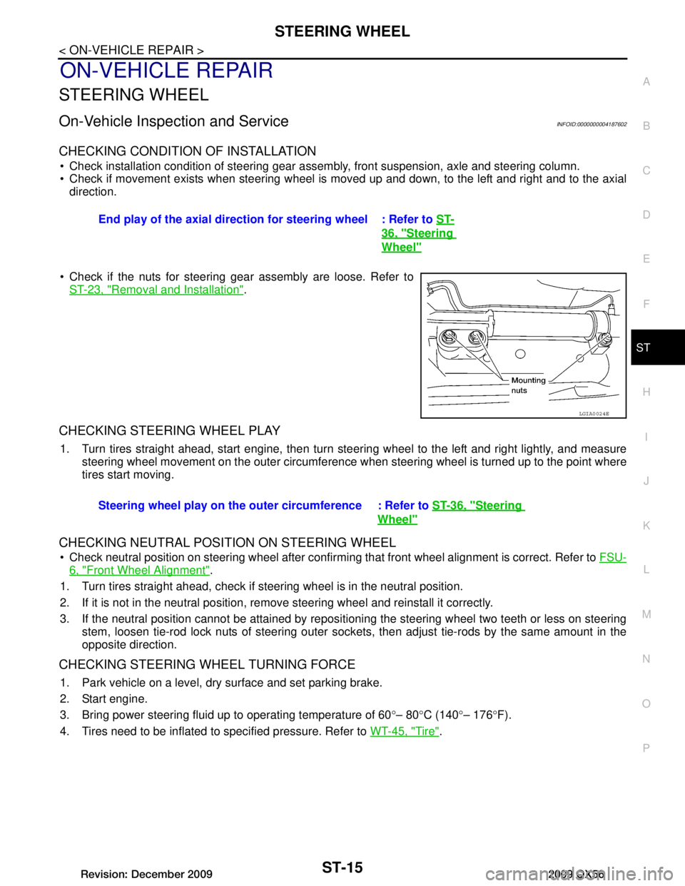
Check if the nuts for steering gear assembly are loose. Refer to ST-23, "Removal and Installation"
.
CHECKING STEERING WHEEL PLAY
1. Turn tires straight ahead, start engine, then turn steer ing wheel to the left and right lightly, and measure
steering wheel movement on the outer circumference when steering wheel is turned up to the point where
tires start moving.
CHECKING NEUTRAL POSITION ON STEERING WHEEL
Check neutral position on steering wheel after confirming that front wheel alignment is correct. Refer to FSU-
6, "Front Wheel Alignment".
1. Turn tires straight ahead, check if st eering wheel is in the neutral position.
2. If it is not in the neutral position, remo ve steering wheel and reinstall it correctly.
3. If the neutral position cannot be attained by repositi oning the steering wheel two teeth or less on steering
stem, loosen tie-rod lock nuts of steering outer socket s, then adjust tie-rods by the same amount in the
opposite direction.
CHECKING STEERING WHEEL TURNING FORCE
1. Park vehicle on a level, dry surface and set parking brake.
2. Start engine.
3. Bring power steering fluid up to operating temperature of 60 °– 80 °C (140 °– 176 °F).
4. Tires need to be inflated to specified pressure. Refer to WT-45, "Tire"
.
End play of the axial direction for steering wheel : Refer to
ST-
36, "Steering
Wheel"
LGIA0024E
Steering wheel play on the outer circumference : Refer to ST-36, "Steering
Wheel"
Revision: December 20092009 QX56
Page 3614 of 4171

POWER STEERING GEAR AND LINKAGEST-23
< REMOVAL AND INSTALLATION >
C
DE
F
H I
J
K L
M A
B
ST
N
O P
POWER STEERING GEAR AND LINKAGE
Removal and InstallationINFOID:0000000004187596
CAUTION:
Spiral cable may snap due to steering operation if steering column is separated from steering gear
assembly. Therefore secure steer ing wheel to avoid turning.
REMOVAL
1. Turn wheels to the straight-ahead position.
2. Remove tires from vehicle using power tool.
3. Remove undercover using power tool.
4. On 4WD models, remove front final drive, then support drive shafts with wire. Refer to DLN-215,
"Removal and Installation".
5. Make sure slit of lower joint fits with the projection on rear cover cap, while checking that mark on steering gear assembly aligns
with mark on rear cover cap.
6. Remove cotter pin at steering outer socket and discard, then loosen nut.
1. Cotter pin 2. Steering Gear Bracket 3. Steering gear insulator
4. Steering gear assembly 5. Washer Front
AWGIA0114GB
SST491C
Revision: December 20092009 QX56
Page 3834 of 4171
TM-186
< ON-VEHICLE MAINTENANCE >
STALL TEST
STALL TEST
Inspection and JudgmentINFOID:0000000003772024
A/T FLUID CHECK
Fluid Leakage and Fluid Level Check
Inspect for fluid leakage and check the fluid level. Refer to TM-179, "Checking the A/T Fluid (ATF)".
Fluid Condition Check
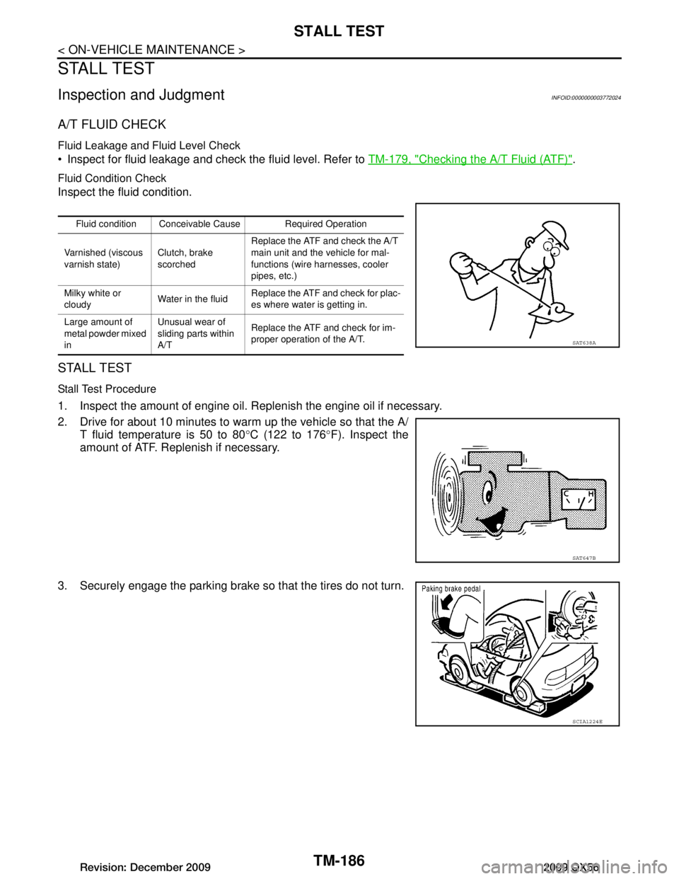
Inspect the fluid condition.
STALL TEST
Stall Test Procedure
1. Inspect the amount of engine oil. Replenish the engine oil if necessary.
2. Drive for about 10 minutes to warm up the vehicle so that the A/
T fluid temperature is 50 to 80 °C (122 to 176 °F). Inspect the
amount of ATF. Replenish if necessary.
3. Securely engage the parking brake so that the tires do not turn.
Fluid condition Conceivable Cause Required Operation
Varnished (viscous
varnish state) Clutch, brake
scorchedReplace the ATF and check the A/T
main unit and the vehicle for mal-
functions (wire harnesses, cooler
pipes, etc.)
Milky white or
cloudy Water in the fluidReplace the ATF and check for plac-
es where water is getting in.
Large amount of
metal powder mixed
in Unusual wear of
sliding parts within
A/T
Replace the ATF and check for im-
proper operation of the A/T.
SAT638A
SAT647B
SCIA1224E
Revision: December 20092009 QX56
Page 3836 of 4171
TM-188
< ON-VEHICLE MAINTENANCE >
LINE PRESSURE TEST
LINE PRESSURE TEST
Inspection and JudgmentINFOID:0000000003772025
LINE PRESSURE TEST
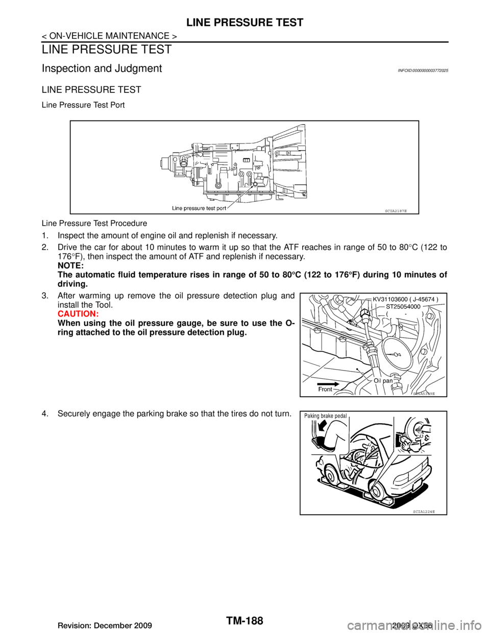
Line Pressure Test Port
Line Pressure Test Procedure
1. Inspect the amount of engine oil and replenish if necessary.
2. Drive the car for about 10 minutes to warm it up so that the ATF reaches in range of 50 to 80°C (122 to
176 °F), then inspect the amount of ATF and replenish if necessary.
NOTE:
The automatic fluid temperatur e rises in range of 50 to 80°C (122 to 176 °F) during 10 minutes of
driving.
3. After warming up remove the oil pressure detection plug and install the Tool.
CAUTION:
When using the oil pressure ga uge, be sure to use the O-
ring attached to the oi l pressure detection plug.
4. Securely engage the parking brake so that the tires do not turn.
SCIA2187E
SCIA5309E
SCIA1224E
Revision: December 20092009 QX56
Page 4043 of 4171

WT-1
SUSPENSION
C
DF
G H
I
J
K L
M
SECTION WT
A
B
WT
N
O PCONTENTS
ROAD WHEELS & TIRES
BASIC INSPECTION ....... .............................3
DIAGNOSIS AND REPAIR WORKFLOW ..... .....3
Repair Work Flow ................................................ ......3
INSPECTION AND ADJUSTMENT .....................5
Preliminary Check ............................................... ......5
Transmitter Wake Up Operation ...............................5
ID Registration Procedure .........................................6
FUNCTION DIAGNOSIS ...............................8
TPMS .............................................................. .....8
System Diagram .................................................. ......8
System Description ...................................................8
System Component .................................................10
DIAGNOSIS SYSTEM (BCM) ............................11
CONSULT-III Function (BCM) ............................. ....11
Self-Diagnosis (With CONSULT-III) ........................12
Self-Diagnosis (Without CONSULT-III) ...................13
COMPONENT DIAGNOSIS .........................14
C1708 - C1711 DATA FROM TRANSMITTER
NOT BEING RECEIVED ................................. ....
14
Description .......................................................... ....14
DTC Logic ...............................................................14
Data from Transmitter Not Being Received ............14
Special Repair Requirement ...................................15
C1712 - C1715, C1720 - C1723, C1724 -
C1727 TRANSMITTER MALFUNCTION ....... ....
16
Description .......................................................... ....16
DTC Logic ...............................................................16
Transmitter Malfunction ...........................................16
Special Repair Requirement ...................................17
C1716 - C1719 TRANSMITTER PRESSURE
MALFUNCTION .............................................. ....
18
Description .......................................................... ....18
DTC Logic ...............................................................18
Transmitter Pressure Malfunction ............................18
Special Repair Requirement ................................ ....18
C1729 VEHICLE SPEED SIGNAL ....................19
Description ...............................................................19
DTC Logic ................................................................19
Vehicle Speed Signal ..............................................19
C1735 IGNITION SIGNAL .................................20
Description ...............................................................20
DTC Logic ................................................................20
Diagnosis Procedure ...............................................20
ECU DIAGNOSIS .........................................21
BCM (BODY CONTROL MODULE) .................21
Reference Value .................................................. ....21
Wiring Diagram ........................................................23
Self-Diagnosis (With CONSULT-III) ........................26
Self-Diagnosis (Without CONSULT-III) ...................27
SYMPTOM DIAGNOSIS ..............................29
TPMS .................................................................29
Symptom Table ................................................... ....29
LOW TIRE PRESSURE WARNING LAMP
DOES NOT TURN ON .......................................
30
Low Tire Pressure Warning Lamp Does Not Come
On When Ignition Switch Is Turned On ...................
30
LOW TIRE PRESSURE WARNING LAMP
STAYS ON ........................................................
31
Low Tire Pressure Warning Lamp Stays On When
Ignition Switch Is Turned On ............................... ....
31
LOW TIRE PRESSURE WARNING LAMP
BLINKS .............................................................
32
Low Tire Pressure Warning Lamp Flashes When
Ignition Switch Is Turned On ...................................
32
HAZARD WARNING LAMPS FLASH ..............33
Revision: December 20092009 QX56
Page 4049 of 4171
INSPECTION AND ADJUSTMENTWT-7
< BASIC INSPECTION >
C
DF
G H
I
J
K L
M A
B
WT
N
O P
This procedure must be done after replacement of a low tire pressure warning transmitter or BCM.
New replacement transmitters are provided "asleep" an d must first be "woken up" before ID registra-
tion can be performed.
1. Connect CONSULT-III.
2. Select "ID REGIST" under BCM.
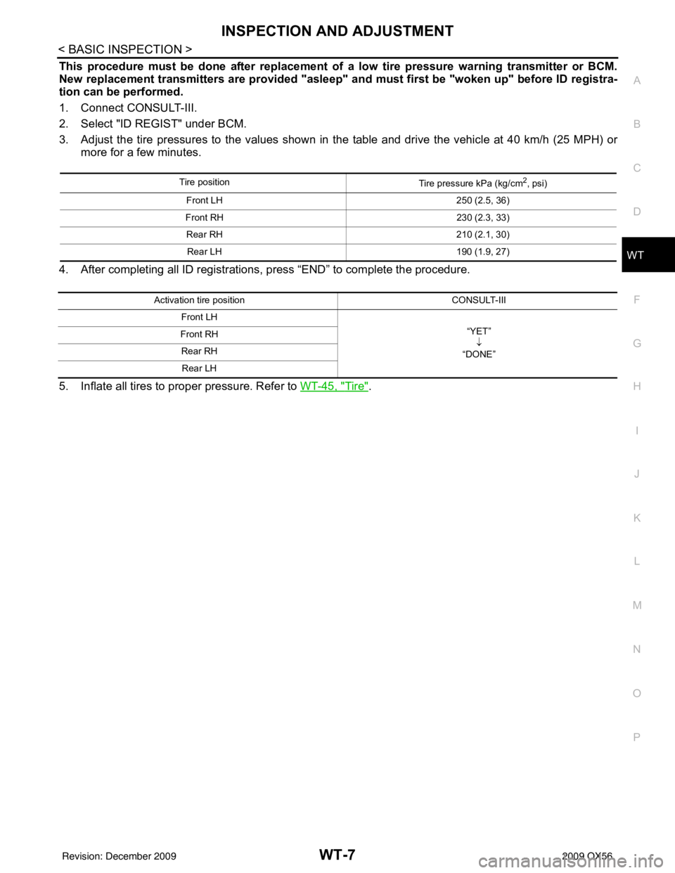
3. Adjust the tire pressures to the values shown in the table and drive the vehicle at 40 km/h (25 MPH) or
more for a few minutes.
4. After completing all ID registrations, press “END” to complete the procedure.
5. Inflate all tires to proper pressure. Refer to WT-45, "
Tire".
Tire position
Tire pressure kPa (kg/cm2, psi)
Front LH 250 (2.5, 36)
Front RH 230 (2.3, 33)
Rear RH 210 (2.1, 30)
Rear LH 190 (1.9, 27)
Activation tire position CONSULT-III
Front LH “YET”↓
“DONE”
Front RH
Rear RHRear LH
Revision: December 20092009 QX56
Page 4060 of 4171
WT-18
< COMPONENT DIAGNOSIS >
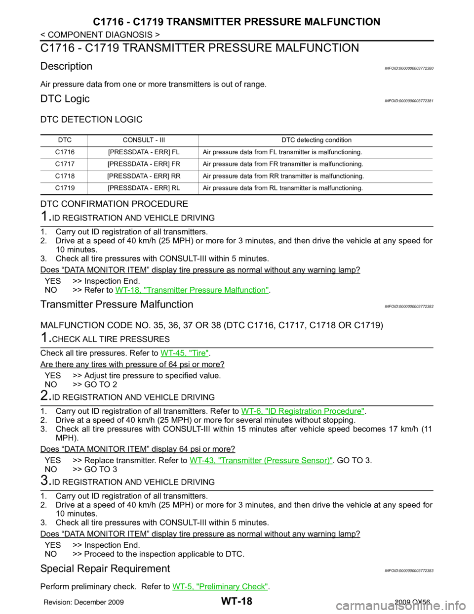
C1716 - C1719 TRANSMITTER PRESSURE MALFUNCTION
C1716 - C1719 TRANSMITTER PRESSURE MALFUNCTION
DescriptionINFOID:0000000003772380
Air pressure data from one or more transmitters is out of range.
DTC LogicINFOID:0000000003772381
DTC DETECTION LOGIC
DTC CONFIRMATION PROCEDURE
1.ID REGISTRATION AND VEHICLE DRIVING
1. Carry out ID registration of all transmitters.
2. Drive at a speed of 40 km/h (25 MPH) or more fo r 3 minutes, and then drive the vehicle at any speed for
10 minutes.
3. Check all tire pressures with CONSULT-III within 5 minutes.
Does
“DATA MONITOR ITEM” display tire pressure as normal without any warning lamp?
YES >> Inspection End.
NO >> Refer to WT-18, "
Transmitter Pressure Malfunction".
Transmitter Pressure MalfunctionINFOID:0000000003772382
MALFUNCTION CODE NO. 35, 36, 37 OR 38 (DTC C1716, C1717, C1718 OR C1719)
1.CHECK ALL TIRE PRESSURES
Check all tire pressures. Refer to WT-45, "
Tire".
Are there any tires with pressure of 64 psi or more?
YES >> Adjust tire pressure to specified value.
NO >> GO TO 2
2.ID REGISTRATION AND VEHICLE DRIVING
1. Carry out ID registration of all transmitters. Refer to WT-6, "
ID Registration Procedure".
2. Drive at a speed of 40 km/h (25 MPH) or more for several minutes without stopping.
3. Check all tire pressures with CONSULT-III within 15 minutes after vehicle speed becomes 17 km/h (11
MPH).
Does
“DATA MONITOR ITEM” display 64 psi or more?
YES >> Replace transmitter. Refer to WT-43, "Transmitter (Pressure Sensor)". GO TO 3.
NO >> GO TO 3
3.ID REGISTRATION AND VEHICLE DRIVING
1. Carry out ID registration of all transmitters.
2. Drive at a speed of 40 km/h (25 MPH) or more fo r 3 minutes, and then drive the vehicle at any speed for
10 minutes.
3. Check all tire pressures with CONSULT-III within 5 minutes.
Does
“DATA MONITOR ITEM” display tire pressure as normal without any warning lamp?
YES >> Inspection End.
NO >> Proceed to the inspection applicable to DTC.
Special Repair RequirementINFOID:0000000003772383
Perform preliminary check. Refer to WT-5, "Preliminary Check".
DTCCONSULT - III DTC detecting condition
C1716 [PRESSDATA - ERR] FL Air pressure data from FL transmitter is malfunctioning.
C1717 [PRESSDATA - ERR] FR Air pressure data from FR transmitter is malfunctioning.
C1718 [PRESSDATA - ERR] RR Air pressure data from RR transmitter is malfunctioning.
C1719 [PRESSDATA - ERR] RL Air pressure data from RL transmitter is malfunctioning.
Revision: December 20092009 QX56
Page 4078 of 4171
WT-36
< SYMPTOM DIAGNOSIS >
NOISE, VIBRATION AND HARSHNESS (NVH) TROUBLESHOOTING
NOISE, VIBRATION AND HARSHNESS (NVH) TROUBLESHOOTING
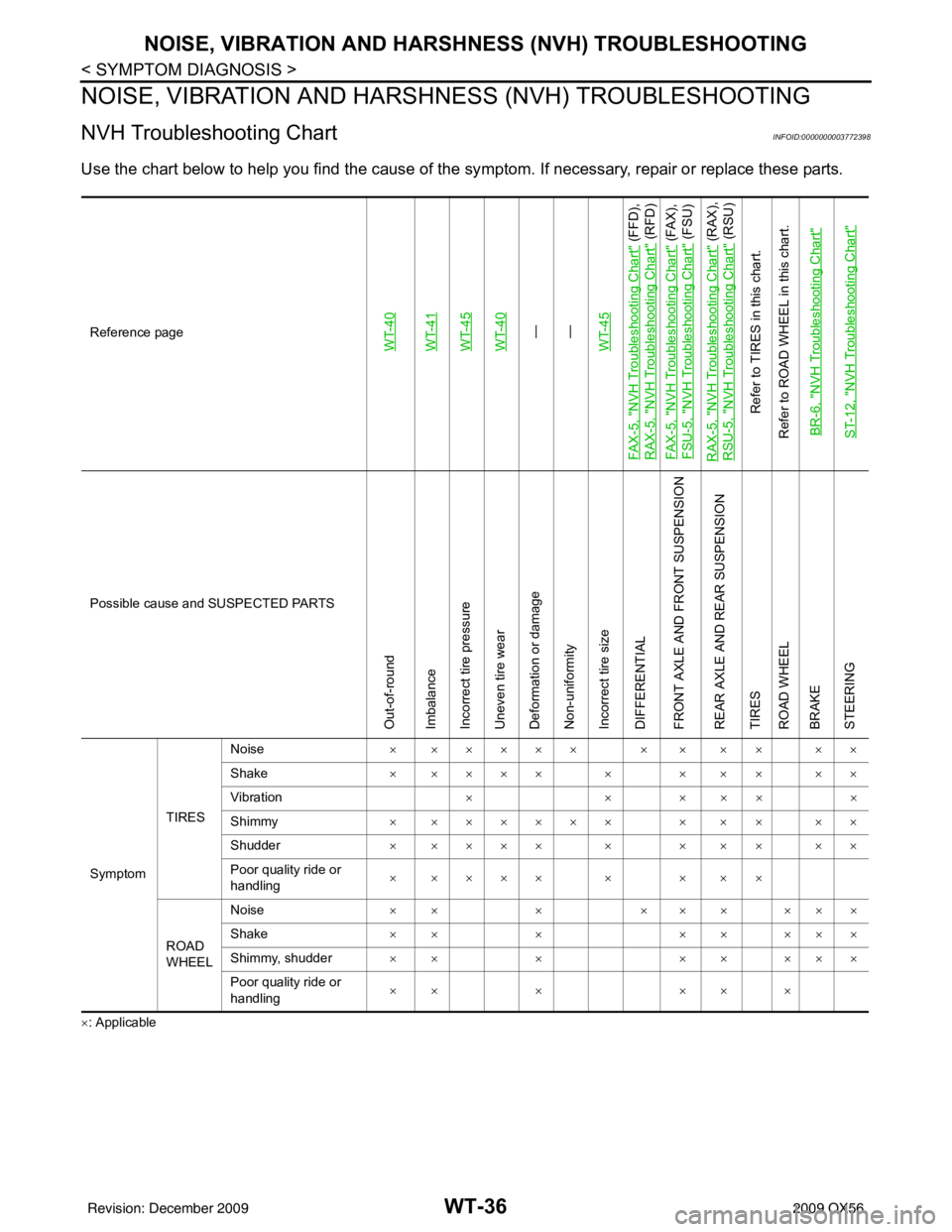
NVH Troubleshooting ChartINFOID:0000000003772398
Use the chart below to help you find the cause of the sy mptom. If necessary, repair or replace these parts.
×: ApplicableReference page
WT-40WT-41WT-45WT-40—
—
WT-45
FA X - 5 , "
NVH Troubleshooting Chart
" (FFD),
RAX-5, "
NVH Troubleshooting Chart
" (RFD)
FA X - 5 , "
NVH Troubleshooting Chart
" (FAX),
FSU-5, "
NVH Troubleshooting Chart
" (FSU)
RAX-5, "
NVH Troubleshooting Chart
" (RAX),
RSU-5, "
NVH Troubleshooting Chart
" (RSU)
Refer to TIRES in this chart.
Refer to ROAD WHEEL in this chart.
BR-6, "
NVH Troubleshooting Chart
"
ST-12, "
NVH Troubleshooting Chart
"
Possible cause and SUSPECTED PARTS
Out-of-round
Imbalance
Incorrect tire pressure
Uneven tire wear
Deformation or damage
Non-uniformity
Incorrect tire size
DIFFERENTIAL
FRONT AXLE AND FRONT SUSPENSION
REAR AXLE AND REAR SUSPENSION
TIRES
ROAD WHEEL
BRAKE
STEERING
Symptom TIRESNoise
× ××××× × × × × ××
Shake × ×××× × × × × ××
Vibration ××× ×××
Shimmy × ×××××× × × × ××
Shudder × ×××× × × × × ××
Poor quality ride or
handling × ×××× × × × ×
ROAD
WHEEL Noise
×× × ××× ×××
Shake ×× × ×× ×××
Shimmy, shudder ×× × ×× ×××
Poor quality ride or
handling ×× ×
×× ×
Revision: December 20092009 QX56