Page 3558 of 4171
SRC-60
< COMPONENT DIAGNOSIS >
B1113 – B1115 SATELLITE SENSOR RH
2.IGNITION SWITCH
After air bag warning lamp lights for 7 seconds, turn ignition switch OFF within 1 second.
>> GO TO 3
3.WAIT TIME
Wait more than 3 seconds.
>> GO TO 4
4.REPEAT STEPS
Repeat steps 1 to 3 twice.
>> GO TO 5
5.IGNITION SWITCH
Turn ignition switch ON.
>> GO TO 6
6.DIAGNOSTIC MODE
SRS system is now in diagnostic mode and AIR BAG warning lamp flashes. Refer to SRC-85, "
Trouble Diag-
nosis without CONSULT-III".
>> END
Diagnosis Procedure (C omponent Diagnosis)INFOID:0000000003775233
Recheck SRS after each replacement.
1.HARNESS CONNECTOR
Is there any visible damage to the connector?
YES or NO
YES >> Replace the harness.
NO >> GO TO 2
2.WIRING HARNESS
Is there any visible damage to the harness?
YES or NO
YES >> Replace the harness.
NO >> GO TO 3
3.RH SIDE AIR BAG SATELLITE SENSOR
Replace the RH side air bag satellite sensor. Refer to SR-15, "
Removal and Installation".
>> GO TO 4
4.AIR BAG DIAGNOSIS SENSOR UNIT
Replace the air bag diagnosis sensor unit. Refer to SR-17, "
Removal and Installation".
>> GO TO 5
5.RELATED HARNESS
Replace the related harness.
Revision: December 20092009 QX56
Page 3561 of 4171
B1XXX AIR BAG DIAGNOSIS SENSOR UNITSRC-63
< COMPONENT DIAGNOSIS >
C
DE
F
G
I
J
K L
M A
B
SRC
N
O P
2.IGNITION SWITCH
After air bag warning lamp lights for 7 seconds, turn ignition switch OFF within 1 second.
>> GO TO 3
3.WAIT TIME
Wait more than 3 seconds.
>> GO TO 4
4.REPEAT STEPS
Repeat steps 1 to 3 twice.
>> GO TO 5
5.IGNITION SWITCH
Turn ignition switch ON.
>> GO TO 6
6.DIAGNOSTIC MODE
SRS system is now in diagnostic mode and AIR BAG warning lamp flashes. Refer to SRC-85, "
Trouble Diag-
nosis without CONSULT-III".
>> END
Diagnosis Procedure (C omponent Diagnosis)INFOID:0000000003775236
Recheck SRS after each replacement.
1.HARNESS CONNECTOR
Is there any visible damage to the connector?
YES or NO
YES >> Replace the harness.
NO >> GO TO 2
2.WIRING HARNESS
Is there any visible damage to the harness?
YES or NO
YES >> Replace the harness.
NO >> GO TO 3
3.AIR BAG DIAGNOSIS SENSOR UNIT
Replace the air bag diagnosis sensor unit. Refer to SR-17, "
Removal and Installation".
>> GO TO 4
4.RELATED HARNESS
Replace the related harness.
>>END
Revision: December 20092009 QX56
Page 3563 of 4171
B1023 PASSENGER AIR BAG OFF INDICATORSRC-65
< COMPONENT DIAGNOSIS >
C
DE
F
G
I
J
K L
M A
B
SRC
N
O P
>> GO TO 2
2.IGNITION SWITCH
After air bag warning lamp lights for 7 seconds, turn ignition switch OFF within 1 second.
>> GO TO 3
3.WAIT TIME
Wait more than 3 seconds.
>> GO TO 4
4.REPEAT STEPS
Repeat steps 1 to 3 twice.
>> GO TO 5
5.IGNITION SWITCH
Turn ignition switch ON.
>> GO TO 6
6.DIAGNOSTIC MODE
SRS system is now in diagnostic mode and AIR BAG warning lamp flashes. Refer to SRC-85, "
Trouble Diag-
nosis without CONSULT-III".
>> END
Diagnosis Procedure (C omponent Diagnosis)INFOID:0000000003775239
Recheck SRS after each replacement.
1.HARNESS CONNECTOR
Is there any visible damage to the connector?
YES or NO
YES >> Replace the harness.
NO >> GO TO 2
2.WIRING HARNESS
Is there any visible damage to the harness?
YES or NO
YES >> Replace the harness.
NO >> GO TO 3
3.FRONT PASSENGER AIR BAG OFF INDICATOR
Replace the front passenger air bag off indicator. Refer to IP-16, "
Removal and Installation".
>> GO TO 4
4.AIR BAG DIAGNOSIS SENSOR UNIT
Replace the air bag diagnosis sensor unit. Refer to SR-17, "
Removal and Installation".
>> GO TO 5
5.RELATED HARNESS
Replace the related harness.
Revision: December 20092009 QX56
Page 3566 of 4171

SRC-68
< COMPONENT DIAGNOSIS >
B1017 – B1022 OCCUPANT CLASSIFICATION SYSTEM
DTC CONFIRMATION PROCEDURE (With CONSULT-lll)
1.INSPECTION START
Turn ignition switch ON.
>> GO TO 2.
2.CHECK SELF-DIAG RESULT
Check for the DTC on CONSULT-lll.
Is the DTC detected?
YES >> Refer to SRC-68, "Diagnosis Procedure (Component Diagnosis)".
NO >> Inspection End.
DTC CONFIRMATION PROCEDURE (Without CONSULT-lll)
NOTE:
SRS will not enter diagnosis mode if no malfunction is detected in user mode.
1.IGNITION SWITCH
Turn ignition switch ON.
>> GO TO 2
2.IGNITION SWITCH
After air bag warning lamp lights for 7 seconds, turn ignition switch OFF within 1 second.
>> GO TO 3
3.WAIT TIME
Wait more than 3 seconds.
>> GO TO 4
4.REPEAT STEPS
Repeat steps 1 to 3 twice.
>> GO TO 5
5.IGNITION SWITCH
Turn ignition switch ON.
>> GO TO 6
6.DIAGNOSTIC MODE
SRS system is now in diagnostic mode and AI R BAG warning lamp flashes. Refer to SRC-7, "
SRS Compo-
nent Parts Location".
>> END
Diagnosis Procedure (C omponent Diagnosis)INFOID:0000000005867462
Recheck SRS after each corrective action.
1.CHECK CURRENT DTC
Does CONSULT-III indicate B1018, B1019, B1020 or B1022?
YES or NO
YES >> GO TO 2
NO >> GO TO 13
Revision: December 20092009 QX56
Page 3685 of 4171
DIAGNOSIS SYSTEM (TCM)TM-37
< FUNCTION DIAGNOSIS >
CEF
G H
I
J
K L
M A
B
TM
N
O P
Diagnosis Procedure without CONSULT-IIIINFOID:0000000004024115
OBD-II SELF-DIAGNOSTIC PROCEDURE (WITH GST)
Refer to EC-72, "Generic Scan Tool (GST) Function".
OBD-II SELF-DIAGNOSTIC PROCEDURE (NO TOOLS)
Refer to EC-55, "Malfunction Indicator Lamp (MIL)".
TCM SELF-DIAGNOSTIC PROCEDURE (NO TOOLS)
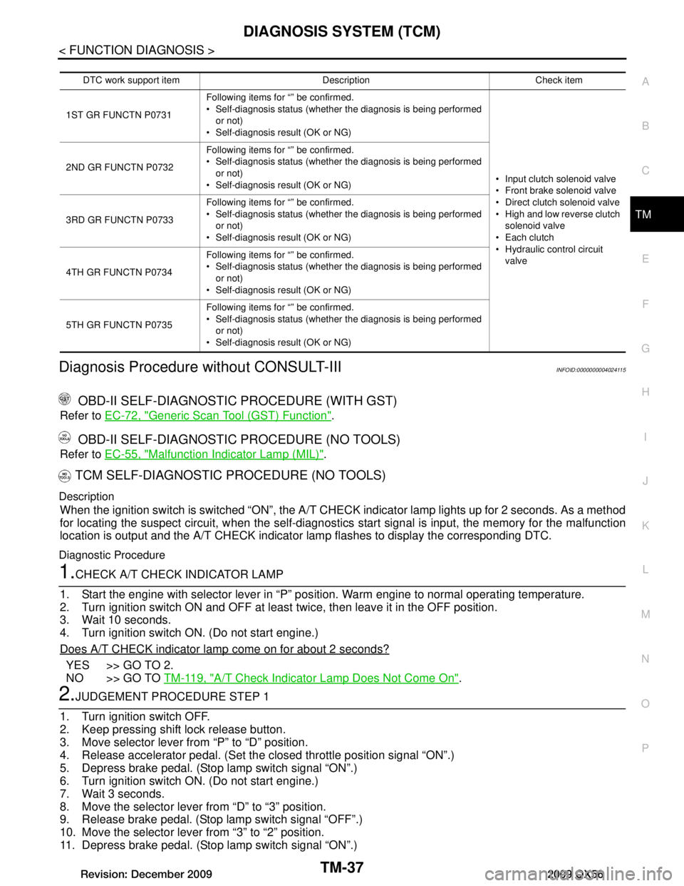
Description
When the ignition switch is switched “ON”, the A/T CHECK indicator lamp lights up for 2 seconds. As a method
for locating the suspect circuit, w hen the self-diagnostics start signal is input, the memory for the malfunction
location is output and the A/T CHECK indicator lamp flashes to display the corresponding DTC.
Diagnostic Procedure
1.CHECK A/T CHECK INDICATOR LAMP
1. Start the engine with selector lever in “P” pos ition. Warm engine to normal operating temperature.
2. Turn ignition switch ON and OFF at least twice, then leave it in the OFF position.
3. Wait 10 seconds.
4. Turn ignition switch ON. (Do not start engine.)
Does A/T CHECK indicator lamp come on for about 2 seconds?
YES >> GO TO 2.
NO >> GO TO TM-119, "A/T Check Indicator Lamp Does Not Come On"
.
2.JUDGEMENT PROCEDURE STEP 1
1. Turn ignition switch OFF.
2. Keep pressing shift lock release button.
3. Move selector lever from “P” to “D” position.
4. Release accelerator pedal. (Set the closed throttle position signal “ON”.)
5. Depress brake pedal. (Stop lamp switch signal “ON”.)
6. Turn ignition switch ON. (Do not start engine.)
7. Wait 3 seconds.
8. Move the selector lever from “D” to “3” position.
9. Release brake pedal. (Stop lamp switch signal “OFF”.)
10. Move the selector lever from “3” to “2” position.
11. Depress brake pedal. (Stop lamp switch signal “ON”.)
DTC work support item Description Check item
1ST GR FUNCTN P0731 Following items for “” be confirmed.
Self-diagnosis status (whether the diagnosis is being performed
or not)
Self-diagnosis result (OK or NG)
Input clutch solenoid valve
Front brake solenoid valve
Direct clutch solenoid valve
High and low reverse clutch solenoid valve
Each clutch
Hydraulic co ntrol circuit
valve
2ND GR FUNCTN P0732
Following items for “” be confirmed.
Self-diagnosis status (whether the diagnosis is being performed
or not)
Self-diagnosis result (OK or NG)
3RD GR FUNCTN P0733 Following items for “” be confirmed.
Self-diagnosis status (whether the diagnosis is being performed
or not)
Self-diagnosis result (OK or NG)
4TH GR FUNCTN P0734 Following items for “” be confirmed.
Self-diagnosis status (whether the diagnosis is being performed
or not)
Self-diagnosis result (OK or NG)
5TH GR FUNCTN P0735 Following items for “” be confirmed.
Self-diagnosis status (whether the diagnosis is being performed
or not)
Self-diagnosis result (OK or NG)
Revision: December 20092009 QX56
Page 3686 of 4171
TM-38
< FUNCTION DIAGNOSIS >
DIAGNOSIS SYSTEM (TCM)
12. Depress accelerator pedal fully and release it.>> GO TO 3.
3.CHECK SELF-DIAGNOSIS CODE
Check A/T CHECK indicator lamp.
Refer to "Judgement Self-diagnosis Code".
If the system does not go into self-diagnostics. Refer to TM-44, "Diagnosis Procedure"
, TM-94, "Diagnosis
Procedure", TM-95, "Diagnosis Procedure".
>> DIAGNOSIS END
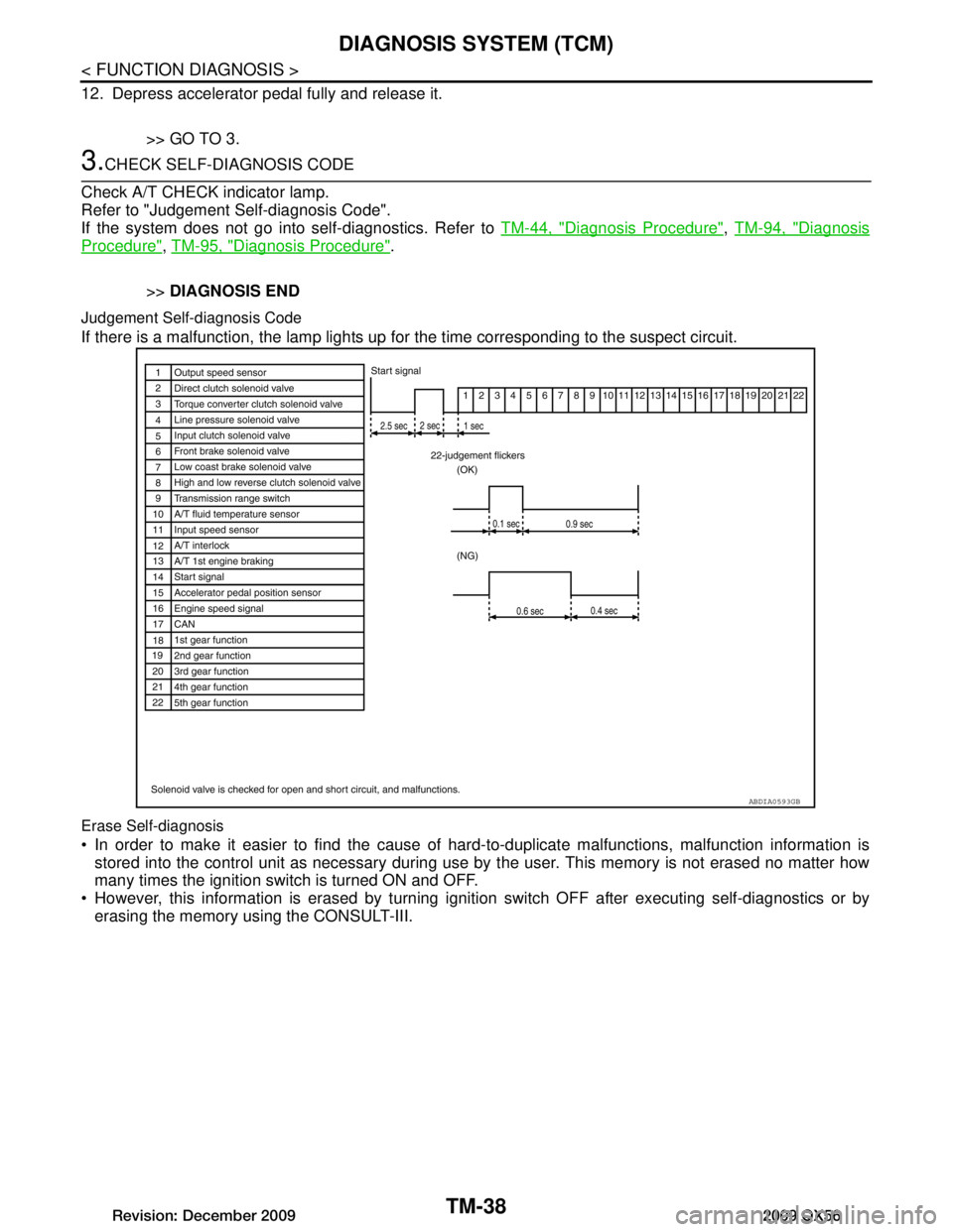
Judgement Self-diagnosis Code
If there is a malfunction, the lamp lights up fo r the time corresponding to the suspect circuit.
Erase Self-diagnosis
In order to make it easier to find the cause of hard-to-duplicate malfunctions, malfunction information is
stored into the control unit as necessary during use by the user. This memory is not erased no matter how
many times the ignition switch is turned ON and OFF.
However, this information is erased by turning igni tion switch OFF after executing self-diagnostics or by
erasing the memory using the CONSULT-III.
ABDIA0593GB
Revision: December 20092009 QX56