2009 INFINITI QX56 cooling
[x] Cancel search: coolingPage 2080 of 4171

EXL-132
< ECU DIAGNOSIS >
IPDM E/R (INTELLIGENT POWER DISTRIBUTION MODULE ENGINE ROOM)
If No CAN Communication Is Available With BCM
IGNITION RELAY MALFUNCTION DETECTION FUNCTION
• IPDM E/R monitors the voltage at the contact circuit and excitation coil circuit of the ignition relay inside it.
• IPDM E/R judges the ignition relay error if the voltage differs between the contact circuit and the excitation
coil circuit.
• If the ignition relay cannot turn OFF due to contact seizure, it activates the tail lamp relay for 10 minutes to alert the user to the ignition relay malfunction when the ignition switch is turned OFF.
NOTE:
The tail lamp turns OFF when the ignition switch is turned ON.
FRONT WIPER CONTROL
IPDM E/R detects front wiper stop posit ion by a front wiper auto stop signal.
When a front wiper auto stop signal is in the conditions listed below, IPDM E/R stops power supply to wiper
after repeating a front wiper 10 second activation and 20 second stop five times.
NOTE:
This operation status can be confirmed on the IPDM E/R “DATA MONITOR” that displays “Block” for the item
“WIP PROT” while the wiper is stopped.
STARTER MOTOR PROTECTION FUNCTION
IPDM E/R turns OFF the starter control relay to protect the starter motor when the starter control relay remains
active for 90 seconds.
Control part Fail-safe in operation
Cooling fan • Turns ON the cooling fan relay when the ignition switch is turned ON
• Turns OFF the cooling fan relay when the ignition switch is turned OFF
Control part
Fail-safe in operation
Headlamp • Turns ON the headlamp low relay when the ignition switch is turned ON
• Turns OFF the headlamp low relay when the ignition switch is turned OFF
• Headlamp high relay OFF
•Parking lamps
• License plate lamps
• Tail lamps • Turns ON the tail lamp relay when the ignition switch is turned ON
• Turns OFF the tail lamp relay when the ignition switch is turned OFF
Front wiper • The status just before activation of fail-safe control is maintained until the ignition
switch is turned OFF while the front wiper is operating at LO or HI speed.
• The wiper is operated at LO speed until the ignition switch is turned OFF if the fail- safe control is activated while the front wipe r is set in the INT mode and the front wiper
motor is operating.
Rear window defogger Rear window defogger relay OFF
A/C compressor A/C relay OFF
Front fog lamps Front fog lamp relay OFF
Ignition switch Ignition relayTail lamp relay
ON ON —
OFF OFF —
Ignition switchFront wiper switch Auto stop signal
ON OFF
Front wiper stop position signal cannot be
input 10 seconds.
ON The signal does not change for 10 seconds.
Revision: December 20092009 QX56
Page 2227 of 4171
TOW TRUCK TOWINGGI-33
< PRECAUTION >
C
DE
F
G H
I
J
K L
M B
GI
N
O P
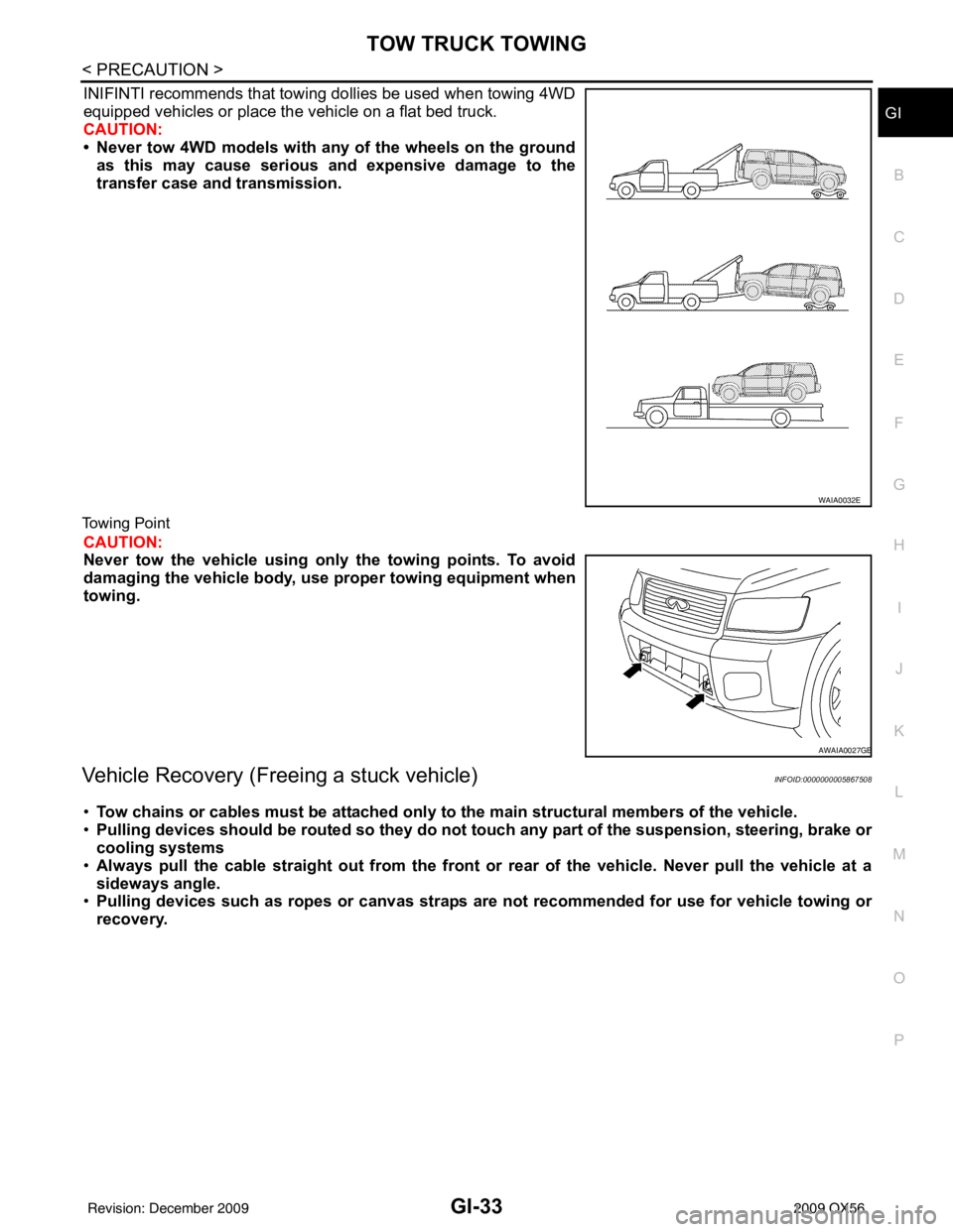
INIFINTI recommends that towing dollies be used when towing 4WD
equipped vehicles or place the vehicle on a flat bed truck.
CAUTION:
• Never tow 4WD models with any of the wheels on the ground as this may cause serious and expensive damage to the
transfer case and transmission.
Towing Point
CAUTION:
Never tow the vehicle using only the towing points. To avoid
damaging the vehicle body, use proper towing equipment when
towing.
Vehicle Recovery (Freeing a stuck vehicle)INFOID:0000000005867508
•Tow chains or cables must be attached only to the main structural members of the vehicle.
• Pulling devices should be routed so they do not touch any part of the suspension, steering, brake or
cooling systems
• Always pull the cable straight out from the front or rear of the vehicle. Never pull the vehicle at a
sideways angle.
• Pulling devices such as ropes or canvas straps are not recommended for use for vehicle towing or
recovery.
WAIA0032E
AWAIA0027GB
Revision: December 20092009 QX56
Page 2269 of 4171

PRECAUTIONSHA-5
< PRECAUTION >
C
DE
F
G H
J
K L
M A
B
HA
N
O P
General Refrigerant PrecautionINFOID:0000000003775289
WARNING:
Do not release refrigerant into the air. Use appr oved recovery/recycling equipment to capture the
refrigerant every time an air co nditioning system is discharged.
Always wear eye and hand protection (goggles and gloves) when working with any refrigerant or air
conditioning system.
Do not store or heat refrigerant containers above 52 °C (125 °F).
Do not heat a refrigerant containe r with an open flame; if container warming is required, place the
bottom of the container in a warm pail of water.
Do not intentionally drop, puncture, or incinerate refrigerant containers.
Keep refrigerant away from open flames: poison ous gas will be produced if refrigerant burns.
Refrigerant will displace oxygen, therefore be certa in to work in well ventilated areas to prevent suf-
focation.
Do not pressure test or leak test HFC-134a (R-134a) service equipment and/or vehicle air condition-
ing systems with compressed air during repair. Some mixtures of air and HFC-134a (R-134a) have
been shown to be combustible at elevated pressures. These mixtures, if ignited, may cause injury or
property damage. Additional health and safety info rmation may be obtained from refrigerant manu-
facturers.
Precaution for Leak Detection DyeINFOID:0000000003775290
The A/C system contains a fluorescent leak detection dy e used for locating refrigerant leaks. An ultraviolet
(UV) lamp is required to illuminate the dye when inspecting for leaks.
Always wear fluorescence enhancing UV safety goggles to protect your eyes and enhance the visibility of
the fluorescent dye.
The fluorescent dye leak detector is not a replacement for an electronic refrigerant leak detector. The fluo-
rescent dye leak detector should be used in conjuncti on with an electronic refrigerant leak detector (J-
41995).
For your safety and the customer's satisfaction, r ead and follow all manufacturer's operating instructions and
precautions prior to performing work.
A compressor shaft seal should not be repaired because of dye seepage. The compressor shaft seal should
only be repaired after confirming the leak with an electronic refrigerant leak detector (J-41995).
Always remove any dye from the leak area after repairs are complete to avoid a misdiagnosis during a future service.
Do not allow dye to come into contact with paint ed body panels or interior components. If dye is spilled,
clean immediately with the approved dye cleaner. Fluores cent dye left on a surface for an extended period of
time cannot be removed .
Do not spray the fluorescent dye cleaning agent on hot surfaces (engine exhaust manifold, etc.).
Do not use more than one refrigerant dye bot tle (1/4 ounce / 7.4 cc) per A/C system.
Leak detection dyes for HFC-134a (R-134a) and CFC-12 (R -12) A/C systems are different. Do not use HFC-
134a (R-134a) leak detection dye in CFC-12 (R-12) A/ C systems or CFC-12 (R-12) leak detection dye in
HFC-134a (R-134a) A/C systems or A/C system damage may result.
The fluorescent properties of the dye will remain for over three (3) years unless a compressor failure occurs.
A/C Identification LabelINFOID:0000000003775291
Vehicles with factory installed fluorescent dye have this identification label on the underside of hood.
Precaution for Refrigerant ConnectionINFOID:0000000003775292
A new type refrigerant connection has been introduced to all refrigerant lines except the following locations.
Expansion valve to cooling unit
Evaporator pipes to evaporator (inside cooling unit)
Refrigerant pressure sensor
FEATURES OF NEW TYPE REFRIGERANT CONNECTION
The O-ring has been relocated. It has also been provided with a groove for proper installation. This reduces the possibility of the O-ring being caught in, or damaged by , the mating part. The sealing direction of the O-
ring is now set vertically in relation to the contacting surface of the mating part to improve sealing character-
istics.
Revision: December 20092009 QX56
Page 2272 of 4171
HA-8
< PRECAUTION >
PRECAUTIONS
Rear A/C
CAUTION:
The new and former refrigerant connections use different O-ring configurations. Do not confuse O-
rings since they are not interchangeable. If a wrong O-ring is installed, refrigerant will leak at or
around the connection.
O-Ring Part Numbers and Specifications
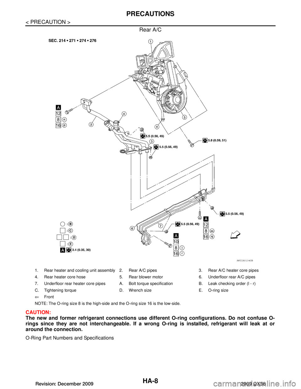
AWIIA0134GB
1. Rear heater and cooling unit assembly 2. Rear A/C pipes 3. Rear A/C heater core pipes
4. Rear heater core hose 5. Rear blower motor 6. Underfloor rear A/C pipes
7. Underfloor rear heater core pipes A. Bolt torque specification B. Leak checking order (l - r)
C. Tightening torque D. Wrench size E. O-ring size
⇐ Front
NOTE: The O-ring size 8 is the high-side and the O-ring size 16 is the low-side.
Revision: December 20092009 QX56
Page 2283 of 4171

OIL
HA-19
< FUNCTION DIAGNOSIS >
C
D E
F
G H
J
K L
M A
B
HA
N
O P
OIL
Maintenance of Oil in CompressorINFOID:0000000003775300
The oil in the compressor circulat es through the system with the refrigerant. Add oil to compressor when
replacing any component or after a large refrigerant leakage has occurred. It is important to maintain the spec-
ified amount.
If oil quantity is not maintained properly , the following malfunctions may result:
Lack of oil: May lead to a seized compressor
Excessive oil: Inadequate cooling (thermal exchange interference)
Revision: December 20092009 QX56
Page 2286 of 4171
HA-22
< ON-VEHICLE MAINTENANCE >
OIL
OIL
Maintenance of Oil Quantity in CompressorINFOID:0000000003775302
The oil in the compressor circulates through the system with the refrigerant. Add oil to compressor when
replacing any component or after a large refrigerant leakage has occurred. It is important to maintain the spec-
ified amount.
If oil quantity is not maintained properly, the following malfunctions may result:
Lack of oil: May lead to a seized compressor
Excessive oil: Inadequate cooling (thermal exchange interference)
OIL
Name: NISSAN A/C System Oil Type S or equivalent
CHECKING AND ADJUSTING
CAUTION:
If excessive oil leakage is noted, do no t perform the oil return operation.
Start the engine and set the following conditions:
Test Condition
Engine speed: Idling to 1,200 rpm
A/C switch: On
Blower fan speed: MAX position
Temp. control: Optional [Set so that intake air temperature is 25 ° to 30 ° C (77 ° to 86 °F)]
Intake position: Recirculation ( )
Perform oil return operation for about ten minutes
Adjust the oil quantity according to the following table.
Oil Adjusting Procedure for Components Replacement Except Compressor
After replacing any of the following major component s, add the correct amount of oil to the system.
Amount of Oil to be Added
*1: If refrigerant leak is small, no addition of oil is needed.
Oil Adjustment Procedure for Compressor Replacement
Part replacedOil to be added to system
Remarks
Amount of oil
m (US fl oz, Imp fl oz)
Front evaporator 75 (2.5, 2.6) —
Rear evaporator 75 (2.5, 2.6) —
Condenser 75 (2.5, 2.6) —
Liquid tank 5 (0.2, 0.2) Add if compressor is not replaced.
In case of refrigerant leak 30 (1.0, 1.1) Large leak
— Small leak *1
Revision: December 20092009 QX56
Page 2291 of 4171
ELECTRICAL LEAK DETECTORHA-27
< ON-VEHICLE MAINTENANCE >
C
DE
F
G H
J
K L
M A
B
HA
N
O P
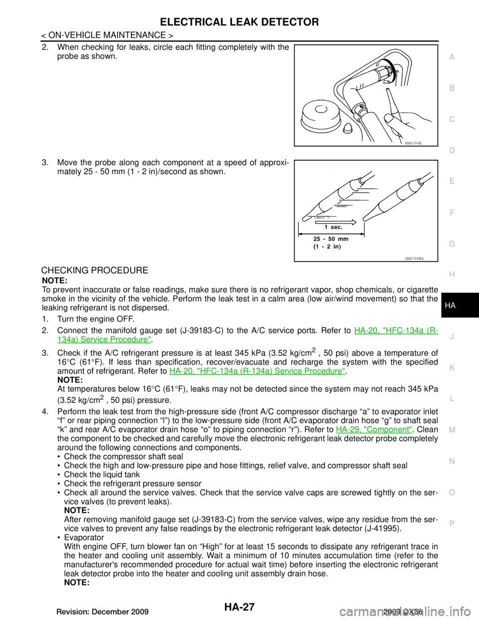
2. When checking for leaks, circle each fitting completely with the probe as shown.
3. Move the probe along each component at a speed of approxi- mately 25 - 50 mm (1 - 2 in)/second as shown.
CHECKING PROCEDURE
NOTE:
To prevent inaccurate or false readings, make sure t here is no refrigerant vapor, shop chemicals, or cigarette
smoke in the vicinity of the vehicle. Perform the leak test in a calm area (low air/wind movement) so that the
leaking refrigerant is not dispersed.
1. Turn the engine OFF.
2. Connect the manifold gauge set (J-39183-C) to the A/C service ports. Refer to HA-20, "HFC-134a (R-
134a) Service Procedure".
3. Check if the A/C refrigerant pressu re is at least 345 kPa (3.52 kg/cm
2 , 50 psi) above a temperature of
16 °C (61 °F). If less than specification, recover/ev acuate and recharge the system with the specified
amount of refrigerant. Refer to HA-20, "HFC-134a (R-134a) Service Procedure"
.
NOTE:
At temperatures below 16 °C (61 °F), leaks may not be detected sinc e the system may not reach 345 kPa
(3.52 kg/cm
2 , 50 psi) pressure.
4. Perform the leak test from the high-pressure side (f ront A/C compressor discharge “a” to evaporator inlet
“f” or rear piping connection “l”) to the low-pressure side (front A/C evaporator drain hose “g” to shaft seal
“k” and rear A/C evaporator drain hose “o” to piping connection “r”). Refer to HA-29, "Component"
. Clean
the component to be checked and carefully move the electronic refrigerant leak detector probe completely
around the following connections and components.
Check the compressor shaft seal
Check the high and low-pressure pipe and hose fitt ings, relief valve, and compressor shaft seal
Check the liquid tank
Check the refrigerant pressure sensor
Check all around the service valves. Check that the service valve caps are screwed tightly on the ser-
vice valves (to prevent leaks).
NOTE:
After removing manifold gauge set (J-39183-C) from t he service valves, wipe any residue from the ser-
vice valves to prevent any false readings by the electronic refrigerant leak detector (J-41995).
Evaporator
With engine OFF, turn blower fan on “High” for at least 15 seconds to dissipate any refrigerant trace in
the heater and cooling unit assembly. Wait a minimum of 10 minutes accumulation time (refer to the
manufacturer's recommended procedure for actual wait time) before inserting the electronic refrigerant
leak detector probe into the heater and cooling unit assembly drain hose.
NOTE:
SHA706E
SHA708EA
Revision: December 20092009 QX56
Page 2294 of 4171
HA-30
< ON-VEHICLE REPAIR >
REFRIGERATION SYSTEM
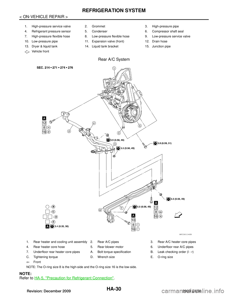
Rear A/C System
NOTE:
Refer to HA-5, "Precaution for Refrigerant Connection"
.
1. High-pressure service valve 2. Grommet 3. High-pressure pipe
4. Refrigerant pressure sensor 5. Condenser 6. Compressor shaft seal
7. High-pressure flexible hose 8. Low-pressure flexible hose 9. Low-pressure service valve
10. Low-pressure pipe 11. Expansion valve (front) 12. Drain hose
13. Dryer & liquid tank 14. Liquid tank bracket 15. Junction pipe
Vehicle front
AWIIA0134GB
1. Rear heater and cooling unit assembly 2. Rear A/C pipes 3. Rear A/C heater core pipes
4. Rear heater core hose 5. Rear blower motor 6. Underfloor rear A/C pipes
7. Underfloor rear heater core pipes A. Bolt torque specification B. Leak checking order (l - r)
C. Tightening torque D. Wrench size E. O-ring size
⇐Front
NOTE: The O-ring size 8 is the high-side and the O-ring size 16 is the low-side.
Revision: December 20092009 QX56