Page 1854 of 4171

EXHAUST MANIFOLD AND THREE WAY CATALYST
EM-31
< ON-VEHICLE REPAIR >
C
D E
F
G H
I
J
K L
M A
EM
NP
O
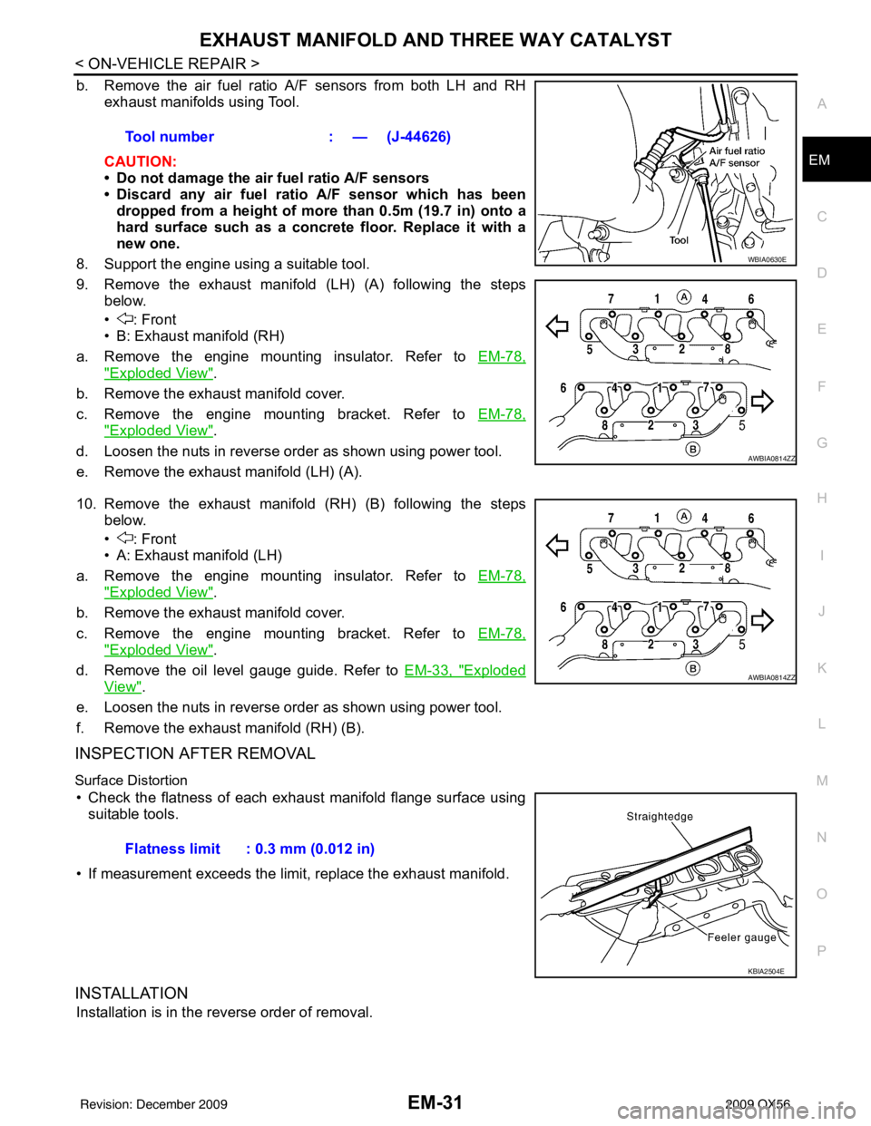
b. Remove the air fuel ratio A/F sensors from both LH and RH
exhaust manifolds using Tool.
CAUTION:
• Do not damage the air fuel ratio A/F sensors
• Discard any air fuel rati o A/F sensor which has been
dropped from a height of more than 0.5m (19.7 in) onto a
hard surface such as a concrete floor. Replace it with a
new one.
8. Support the engine using a suitable tool.
9. Remove the exhaust manifold (LH) (A) following the steps below.
• : Front
• B: Exhaust manifold (RH)
a. Remove the engine mounting insulator. Refer to EM-78,
"Exploded View".
b. Remove the exhaust manifold cover.
c. Remove the engine mounting bracket. Refer to EM-78,
"Exploded View".
d. Loosen the nuts in reverse order as shown using power tool.
e. Remove the exhaust manifold (LH) (A).
10. Remove the exhaust manifold (RH) (B) following the steps below.
• : Front
• A: Exhaust manifold (LH)
a. Remove the engine mounting insulator. Refer to EM-78,
"Exploded View".
b. Remove the exhaust manifold cover.
c. Remove the engine mounting bracket. Refer to EM-78,
"Exploded View".
d. Remove the oil level gauge guide. Refer to EM-33, "
Exploded
View".
e. Loosen the nuts in reverse order as shown using power tool.
f. Remove the exhaust manifold (RH) (B).
INSPECTION AFTER REMOVAL
Surface Distortion
• Check the flatness of each exhaust manifold flange surface using suitable tools.
• If measurement exceeds the limit, replace the exhaust manifold.
INSTALLATION
Installation is in the reverse order of removal. Tool number
: — (J-44626)
WBIA0630E
AWBIA0814ZZ
AWBIA0814ZZ
Flatness limit : 0.3 mm (0.012 in)
KBIA2504E
Revision: December 20092009 QX56
Page 1856 of 4171
OIL PAN AND OIL STRAINEREM-33
< ON-VEHICLE REPAIR >
C
DE
F
G H
I
J
K L
M A
EM
NP
O
OIL PAN AND OIL STRAINER
Exploded ViewINFOID:0000000005885878
Removal and InstallationINFOID:0000000005885879
REMOVAL
WARNING:
To avoid the danger of being scalded, never drain the engine oil when the engine is hot.
1. Remove the engine. Refer to
EM-78, "
Removal and Installation".
2. Remove the oil pan (lower) using the following steps.
1. Oil pan (upper) 2. O-ring3. O-ring
4. O-ring 5. O-ring (with collar)6. Oil level gauge guide
7. Oil level gauge 8. O-ring9. Connector bolt
10. Oil filter 11. Oil cooler12. Relief valve
13. Oil pressure switch 14. Gasket15. Drain plug
16. Oil pan (lower) 17. Oil strainer
KBIA2465E
Revision: December 20092009 QX56
Page 1857 of 4171

EM-34
< ON-VEHICLE REPAIR >
OIL PAN AND OIL STRAINER
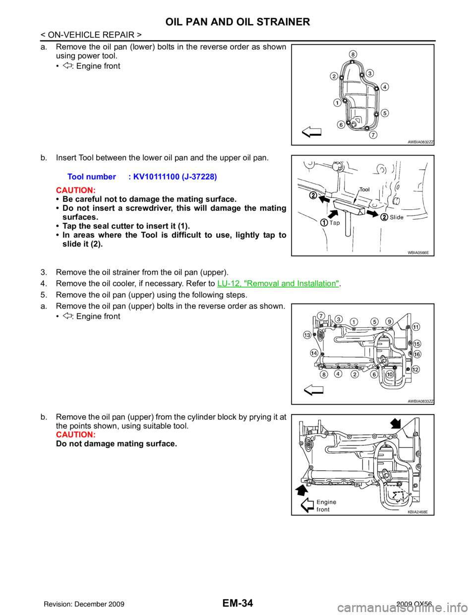
a. Remove the oil pan (lower) bolts in the reverse order as shownusing power tool.
• : Engine front
b. Insert Tool between the lower oil pan and the upper oil pan. CAUTION:
• Be careful not to damage the mating surface.
• Do not insert a screwdriver, this will damage the matingsurfaces.
• Tap the seal cutter to insert it (1).
• In areas where the Tool is diffi cult to use, lightly tap to
slide it (2).
3. Remove the oil strainer from the oil pan (upper).
4. Remove the oil cooler, if necessary. Refer to LU-12, "
Removal and Installation".
5. Remove the oil pan (upper) using the following steps.
a. Remove the oil pan (upper) bolts in the reverse order as shown. • : Engine front
b. Remove the oil pan (upper) from the cylinder block by prying it at the points shown, using suitable tool.
CAUTION:
Do not damage mating surface.
AWBIA0832ZZ
Tool number : KV10111100 (J-37228)
WBIA0566E
AWBIA0833ZZ
KBIA2468E
Revision: December 20092009 QX56
Page 1859 of 4171
EM-36
< ON-VEHICLE REPAIR >
OIL PAN AND OIL STRAINER
3. Install the oil pan (lower).
a. Apply liquid gasket thoroughly as shown.Use Genuine RTV Silicone Sealant or equivalent. Refer to
GI-15, "
Recommended Chemical Products and Sealants".
b. Tighten the oil pan (lower) bolts in numerical order as shown.
4. Install the oil pan drain plug.
5. Install engine assembly. Refer to EM-78, "
Removal and Installation".
• Do not fill the engine oil for at least 30 minutes after oil pan is installed.
INSPECTION AFTER INSTALLATION
1. Check engine oil level and add engine oil if necessary. Refer to LU-8, "Inspection".
2. Start the engine, and check for leaks of engine oil.
3. Stop engine and wait for 10 minutes.
4. Check engine oil level again.
KBIA2471E
PBIC2595E
Revision: December 20092009 QX56
Page 1860 of 4171
IGNITION COILEM-37
< ON-VEHICLE REPAIR >
C
DE
F
G H
I
J
K L
M A
EM
NP
O
IGNITION COIL
Exploded ViewINFOID:0000000005885880
Removal and InstallationINFOID:0000000005885881
REMOVAL
1. Remove the engine room cover using power tool. Refer to
EM-24, "Removal and Installation".
2. Disconnect the harness connector from the ignition coil.
3. Remove the ignition coil. CAUTION:
Do not shock ignition coil.
INSTALLATION
Installation is in the reverse order of removal.
1. Ignition coil 2. Spark plug
WBIA0796E
Revision: December 20092009 QX56
Page 1861 of 4171
EM-38
< ON-VEHICLE REPAIR >
ROCKER COVER
ROCKER COVER
Exploded ViewINFOID:0000000005885882
Removal and InstallationINFOID:0000000005885883
REMOVAL
1. Remove the engine room cover using power tool. Refer to EM-24, "Removal and Installation".
2. Move the harness on the upper rocker cover and its peripheral aside.
3. Remove the ignition coils. Refer to EM-37, "
Removal and Installation".
4. Disconnect crankcase ventilation hoses from rocker covers.
5. Remove the PCV hoses from the PCV control valves.
6. Loosen the bolts in reverse order shown using power tool for rocker cover (A) or (B).
• : Engine front
CAUTION:
Do not hold the rocker cover ( RH) (B) by the oil filler neck.
INSTALLATION
1. Rocker cover (LH) 2. PCV control valve3. O-ring
4. Rocker cover gasket (LH) 5. Rocker cover (RH)6. PCV control valve
7. O-ring 8. Oil filler cap9. Rocker cover gasket (RH)
KBIA2508E
WBIA0697E
Revision: December 20092009 QX56
Page 1862 of 4171

ROCKER COVEREM-39
< ON-VEHICLE REPAIR >
C
DE
F
G H
I
J
K L
M A
EM
NP
O
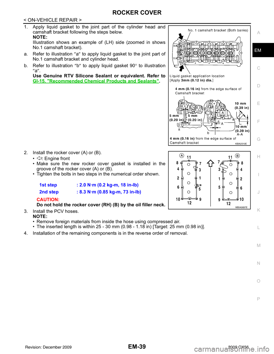
1. Apply liquid gasket to the joint part of the cylinder head and
camshaft bracket following the steps below.
NOTE:
Illustration shows an example of (LH) side (zoomed in shows
No.1 camshaft bracket).
a. Refer to illustration ″a ″ to apply liquid gasket to the joint part of
No.1 camshaft bracket and cylinder head.
b. Refer to illustration ″b ″ to apply liquid gasket 90° to illustration
″ a ″.
Use Genuine RTV Silicone Seal ant or equivalent. Refer to
GI-15, "
Recommended Chemical Products and Sealants".
2. Install the rocker cover (A) or (B). • : Engine front
• Make sure the new rocker cover gasket is installed in thegroove of the rocker cover (A) or (B).
• Tighten the bolts in two steps in the numerical order shown.
CAUTION:
Do not hold the rocker cover ( RH) (B) by the oil filler neck.
3. Install the PCV hoses. NOTE:
• Remove foreign materials from inside the hose using compressed air.
• The inserted length is within 25 - 30 mm (0.98 - 1.18 in) [Target: 25 mm (0.98 in)].
4. Installation of the remaining components is in the reverse order of removal.
KBIA2510E
1st step : 2.0 N·m (0.2 kg-m, 18 in-lb)
2nd step : 8.3 N·m (0.85 kg-m, 73 in-lb)
WBIA0697E
Revision: December 20092009 QX56
Page 1864 of 4171

FUEL INJECTOR AND FUEL TUBEEM-41
< ON-VEHICLE REPAIR >
C
DE
F
G H
I
J
K L
M A
EM
NP
O
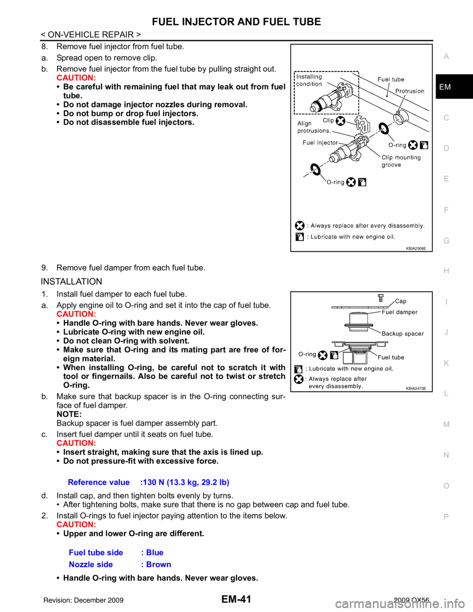
8. Remove fuel injector from fuel tube.
a. Spread open to remove clip.
b. Remove fuel injector from the
fuel tube by pulling straight out.
CAUTION:
• Be careful with remaining fuel that may leak out from fuel
tube.
• Do not damage injector nozzles during removal.
• Do not bump or drop fuel injectors.
• Do not disassemble fuel injectors.
9. Remove fuel damper from each fuel tube.
INSTALLATION
1. Install fuel damper to each fuel tube.
a. Apply engine oil to O-ring and set it into the cap of fuel tube. CAUTION:
• Handle O-ring with bare hands. Never wear gloves.
• Lubricate O-ring with new engine oil.
• Do not clean O-ring with solvent.
• Make sure that O-ring and its mating part are free of for- eign material.
• When installing O-ring, be car eful not to scratch it with
tool or fingernails. Also be careful not to twist or stretch
O-ring.
b. Make sure that backup spacer is in the O-ring connecting sur- face of fuel damper.
NOTE:
Backup spacer is fuel damper assembly part.
c. Insert fuel damper until it seats on fuel tube. CAUTION:
• Insert straight, making sure that the axis is lined up.
• Do not pressure-fit with excessive force.
d. Install cap, and then tighten bolts evenly by turns. • After tightening bolts, make sure that there is no gap between cap and fuel tube.
2. Install O-rings to fuel injector paying attention to the items below. CAUTION:
• Upper and lower O-ring are different.
• Handle O-ring with bare hands. Never wear gloves.
KBIA2506E
Reference value :130 N (13.3 kg, 29.2 lb)
Fuel tube side : Blue
Nozzle side : Brown
KBIA2473E
Revision: December 20092009 QX56