2009 INFINITI QX56 Rax
[x] Cancel search: RaxPage 3090 of 4171
REAR DRIVE SHAFTRAX-15
< DISASSEMBLY AND ASSEMBLY >
CEF
G H
I
J
K L
M A
B
RAX
N
O P
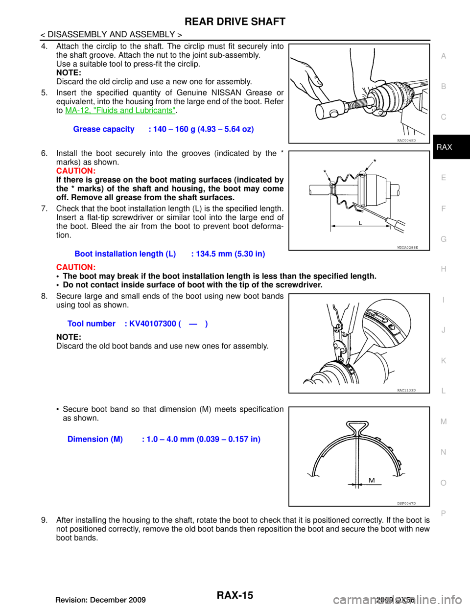
4. Attach the circlip to the shaft. The circlip must fit securely into
the shaft groove. Attach the nut to the joint sub-assembly.
Use a suitable tool to press-fit the circlip.
NOTE:
Discard the old circlip and use a new one for assembly.
5. Insert the specified quantit y of Genuine NISSAN Grease or
equivalent, into the housing from the large end of the boot. Refer
to MA-12, "Fluids and Lubricants"
.
6. Install the boot securely into the grooves (indicated by the * marks) as shown.
CAUTION:
If there is grease on the boot mating surfaces (indicated by
the * marks) of the shaft and housing, the boot may come
off. Remove all grease from the shaft surfaces.
7. Check that the boot installation length (L) is the specified length. Insert a flat-tip screwdriver or similar tool into the large end of
the boot. Bleed the air from the boot to prevent boot deforma-
tion.
CAUTION:
The boot may break if the boot installation length is less than the specified length.
Do not contact inside surface of boot with the tip of the screwdriver.
8. Secure large and small ends of the boot using new boot bands using tool as shown.
NOTE:
Discard the old boot bands and use new ones for assembly.
Secure boot band so that dimension (M) meets specificationas shown.
9. After installing the housing to the shaft, rotate the boot to check that it is positioned correctly. If the boot is
not positioned correctly, remove the old boot bands then reposition the boot and secure the boot with new
boot bands. Grease capacity : 140
− 160 g (4.93 − 5.64 oz)
RAC0049D
Boot installation length (L) : 134.5 mm (5.30 in)
Tool number : KV40107300 ( — )
WDIA0288E
RAC1133D
Dimension (M) : 1.0 – 4.0 mm (0.039 – 0.157 in)
DSF0047D
Revision: December 20092009 QX56
Page 3091 of 4171
RAX-16
< SERVICE DATA AND SPECIFICATIONS (SDS)
SERVICE DATA AND SPECIFICATIONS (SDS)
SERVICE DATA AND SPECIFICATIONS (SDS)
SERVICE DATA AND SPECIFICATIONS (SDS)
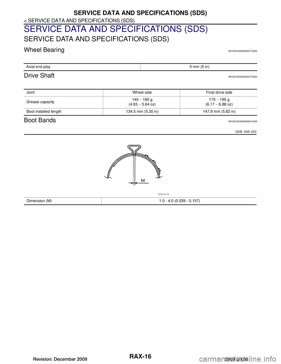
Wheel BearingINFOID:0000000003772263
Drive ShaftINFOID:0000000003772264
Boot BandsINFOID:0000000004212446
Unit: mm (in)
Axial end play0 mm (0 in)
Joint Wheel side Final drive side
Grease capacity140
− 160 g
(4.93 − 5.64 oz) 175
− 195 g
(6.17 − 6.88 oz)
Boot installed length 134.5 mm (5.30 in) 147.9 mm (5.82 in)
Dimension (M) 1.0 - 4.0 (0.039 - 0.157)
DSF0047D
Revision: December 20092009 QX56
Page 3153 of 4171
NOISE, VIBRATION AND HARSHNESS (NVH) TROUBLESHOOTINGRSU-5
< SYMPTOM DIAGNOSIS >
C
DF
G H
I
J
K L
M A
B
RSU
N
O P
SYMPTOM DIAGNOSIS
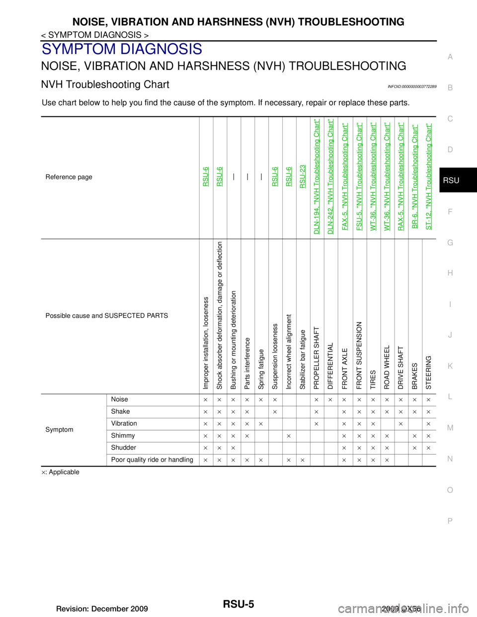
NOISE, VIBRATION AND HARSHN ESS (NVH) TROUBLESHOOTING
NVH Troubleshooting ChartINFOID:0000000003772289
Use chart below to help you find the cause of the symp tom. If necessary, repair or replace these parts.
×: ApplicableReference page
RSU-6RSU-6—
—
—
RSU-6RSU-6RSU-23
DLN-194, "NVH Troubleshooting Chart"DLN-242, "NVH Troubleshooting Chart"FAX-5, "NVH Troubleshooting Chart"FSU-5, "NVH Troubleshooting Chart"WT-36, "NVH Troubleshooting Chart"WT-36, "NVH Troubleshooting Chart"RAX-5, "NVH Troubleshooting Chart"BR-6, "NVH Troubleshooting Chart"ST-12, "NVH Troubleshooting Chart"
Possible cause and SUSPECTED PARTS
Improper installation, looseness
Shock absorber deformation, damage or deflection
Bushing or mounting deterioration
Parts interference
Spring fatigue
Suspension looseness
Incorrect wheel alignment
Stabilizer bar fatigue
PROPELLER SHAFT
DIFFERENTIAL
FRONT AXLE
FRONT SUSPENSION
TIRES
ROAD WHEEL
DRIVE SHAFT
BRAKES
STEERING
Symptom Noise
×××××× ××× ××××××
Shake ×××× × × × ××××××
Vibration ××××× × × ×× × ×
Shimmy ×××× × × ××× ××
Shudder ××× × ××× ××
Poor quality ride or handling ××××× ×× × ×××
Revision: December 20092009 QX56
Page 3161 of 4171
REAR SUSPENSION MEMBERRSU-13
< REMOVAL AND INSTALLATION >
C
DF
G H
I
J
K L
M A
B
RSU
N
O P
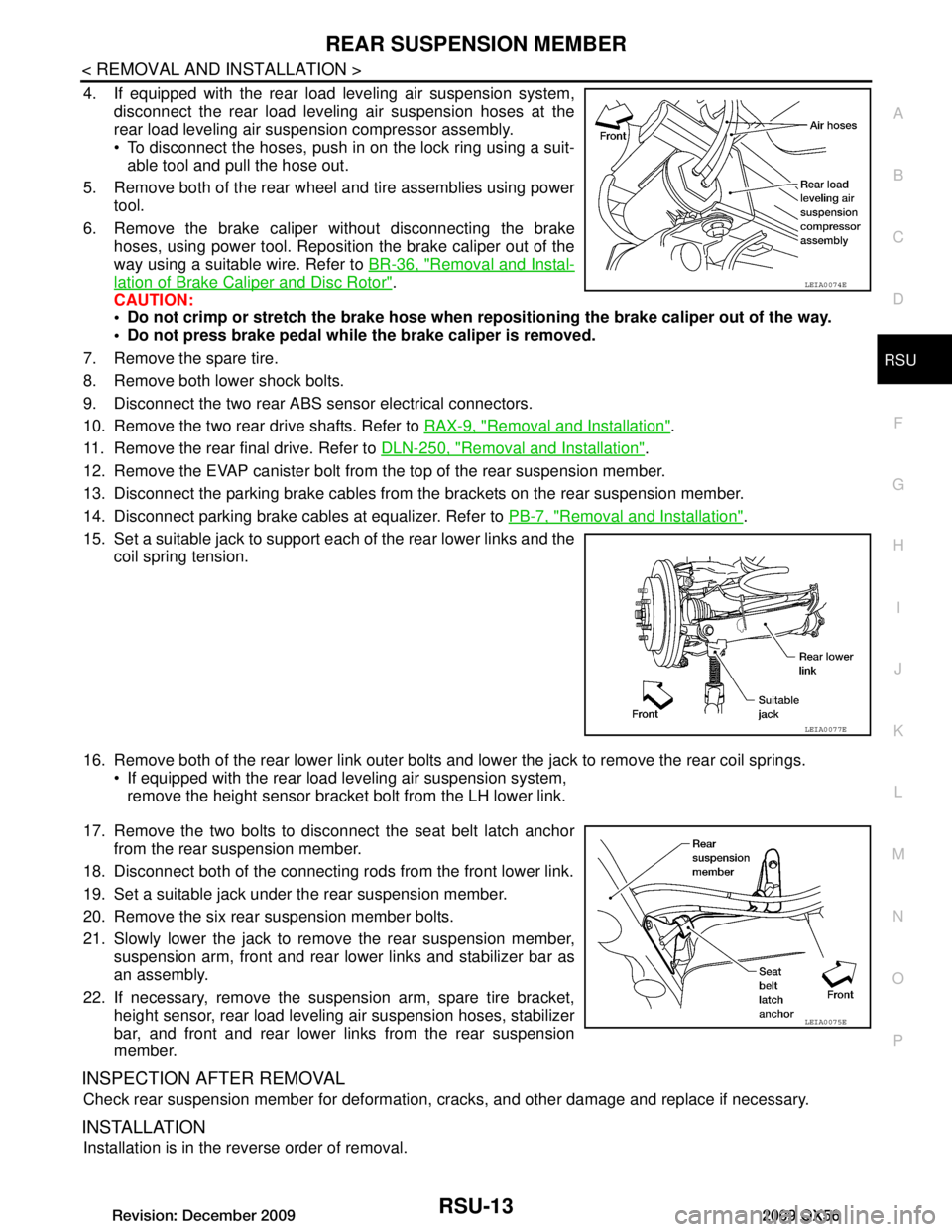
4. If equipped with the rear load leveling air suspension system, disconnect the rear load leveling air suspension hoses at the
rear load leveling air suspension compressor assembly.
To disconnect the hoses, push in on the lock ring using a suit-
able tool and pull the hose out.
5. Remove both of the rear wheel and tire assemblies using power tool.
6. Remove the brake caliper without disconnecting the brake hoses, using power tool. Reposition the brake caliper out of the
way using a suitable wire. Refer to BR-36, "Removal and Instal-
lation of Brake Caliper and Disc Rotor".
CAUTION:
Do not crimp or stretch the brake hose when re positioning the brake caliper out of the way.
Do not press brake pedal while the brake caliper is removed.
7. Remove the spare tire.
8. Remove both lower shock bolts.
9. Disconnect the two rear ABS sensor electrical connectors.
10. Remove the two rear drive shafts. Refer to RAX-9, "Removal and Installation"
.
11. Remove the rear final drive. Refer to DLN-250, "Removal and Installation"
.
12. Remove the EVAP canister bolt from the top of the rear suspension member.
13. Disconnect the parking brake cables from t he brackets on the rear suspension member.
14. Disconnect parking brake cables at equalizer. Refer to PB-7, "Removal and Installation"
.
15. Set a suitable jack to support each of the rear lower links and the coil spring tension.
16. Remove both of the rear lower link outer bolts and lower the jack to remove the rear coil springs. If equipped with the rear load leveling air suspension system,
remove the height sensor bracket bolt from the LH lower link.
17. Remove the two bolts to disconnect the seat belt latch anchor from the rear suspension member.
18. Disconnect both of the connecting r ods from the front lower link.
19. Set a suitable jack under the rear suspension member.
20. Remove the six rear suspension member bolts.
21. Slowly lower the jack to remove the rear suspension member, suspension arm, front and rear lower links and stabilizer bar as
an assembly.
22. If necessary, remove the suspension arm, spare tire bracket, height sensor, rear load leveling air suspension hoses, stabilizer
bar, and front and rear lower links from the rear suspension
member.
INSPECTION AFTER REMOVAL
Check rear suspension member for deformation, cracks, and other damage and replace if necessary.
INSTALLATION
Installation is in the reverse order of removal.
LEIA0074E
LEIA0077E
LEIA0075E
Revision: December 20092009 QX56
Page 3766 of 4171
TM-118
< ECU DIAGNOSIS >
TCM
*1: These numbers are prescribed by SAE J2012.
*2: These malfunctions cannot be displayed MIL if another malfunction is assigned to MIL.
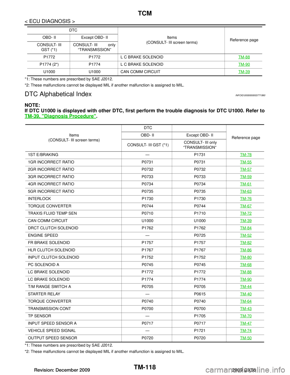
DTC Alphabetical IndexINFOID:0000000003771990
NOTE:
If DTC U1000 is displayed with other DTC, first perform the trouble diagnosis for DTC U1000. Refer to
TM-39, "Diagnosis Procedure"
.
*1: These numbers are prescribed by SAE J2012.
*2: These malfunctions cannot be displayed MIL if another malfunction is assigned to MIL. P1772 P1772 L C BRAKE SOLENOID
TM-88
P1774 (2*) P1774 L C BRAKE SOLENOID TM-90
U1000 U1000 CAN COMM CIRCUITTM-39
DTC
Items
(CONSULT- III screen terms) Reference page
OBD- II Except OBD- II
CONSULT- III GST (*1) CONSULT- III only
“TRANSMISSION”
Items
(CONSULT- III screen terms) DTC
Reference page
OBD- II Except OBD- II
CONSULT- III GST (*1) CONSULT- III only
“TRANSMISSION”
1ST E/BRAKING — P1731 TM-78
1GR INCORRECT RATIO P0731 P0731TM-55
2GR INCORRECT RATIO P0732 P0732TM-57
3GR INCORRECT RATIO P0733 P0733TM-59
4GR INCORRECT RATIO P0734 P0734TM-61
5GR INCORRECT RATIO P0735 P0735TM-63
INTERLOCK P1730 P1730TM-76
TORQUE CONVERTER P0744 P0744 TM-67
TRAXIS FLUID TEMP SEN P0710 P1710TM-72
CAN COMM CIRCUIT U1000 U1000TM-39
DRCT CLUTCH SOLENOID P1762 P1762 TM-84
ENGINE SPEED — P0725 TM-52
FR BRAKE SOLENOID P1757 P1757TM-82
HLR CLUTCH SOLENOID P1767 P1767TM-86
INPUT CLUTCH SOLENOID P1752 P1752TM-80
PC SOLENOID A P0745 P0745TM-68
LC BRAKE SOLENOID P1772 P1772TM-88
LC BRAKE SOLENOID P1774 P1774 TM-90
T/M RANGE SWITCH A P0705 P0705TM-44
STARTER RELAY — P0615TM-40
TORQUE CONVERTER P0740 P0740TM-64
TRANSMISSION CONT P0700 P0700TM-43
TP SENSOR — P1705TM-70
INPUT SPEED SENSOR A P0717 P0717TM-47
VEHICLE SPEED SIGNAL — P1721TM-74
OUTPUT SPEED SENSOR P0720 P0720TM-50
Revision: December 20092009 QX56
Page 4078 of 4171
WT-36
< SYMPTOM DIAGNOSIS >
NOISE, VIBRATION AND HARSHNESS (NVH) TROUBLESHOOTING
NOISE, VIBRATION AND HARSHNESS (NVH) TROUBLESHOOTING
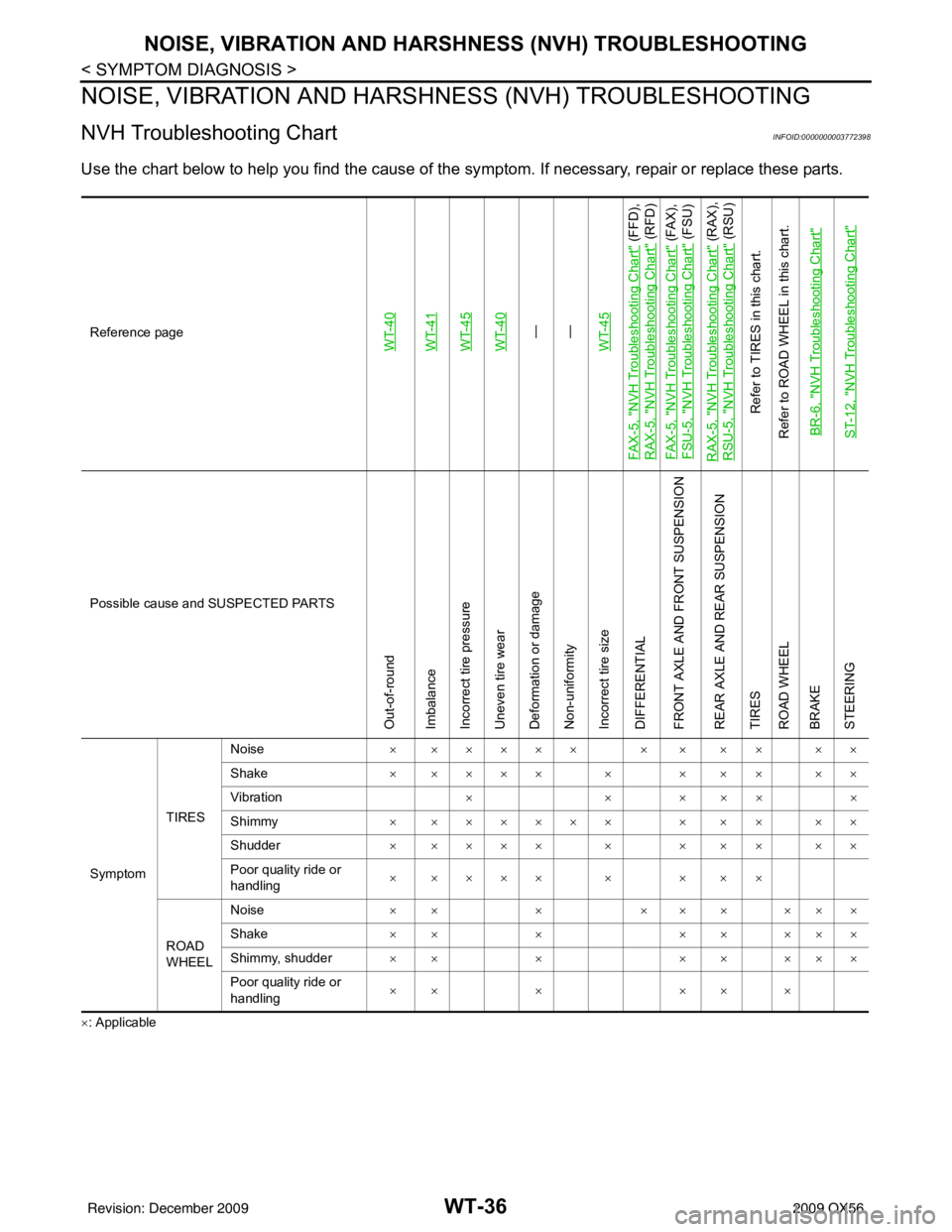
NVH Troubleshooting ChartINFOID:0000000003772398
Use the chart below to help you find the cause of the sy mptom. If necessary, repair or replace these parts.
×: ApplicableReference page
WT-40WT-41WT-45WT-40—
—
WT-45
FA X - 5 , "
NVH Troubleshooting Chart
" (FFD),
RAX-5, "
NVH Troubleshooting Chart
" (RFD)
FA X - 5 , "
NVH Troubleshooting Chart
" (FAX),
FSU-5, "
NVH Troubleshooting Chart
" (FSU)
RAX-5, "
NVH Troubleshooting Chart
" (RAX),
RSU-5, "
NVH Troubleshooting Chart
" (RSU)
Refer to TIRES in this chart.
Refer to ROAD WHEEL in this chart.
BR-6, "
NVH Troubleshooting Chart
"
ST-12, "
NVH Troubleshooting Chart
"
Possible cause and SUSPECTED PARTS
Out-of-round
Imbalance
Incorrect tire pressure
Uneven tire wear
Deformation or damage
Non-uniformity
Incorrect tire size
DIFFERENTIAL
FRONT AXLE AND FRONT SUSPENSION
REAR AXLE AND REAR SUSPENSION
TIRES
ROAD WHEEL
BRAKE
STEERING
Symptom TIRESNoise
× ××××× × × × × ××
Shake × ×××× × × × × ××
Vibration ××× ×××
Shimmy × ×××××× × × × ××
Shudder × ×××× × × × × ××
Poor quality ride or
handling × ×××× × × × ×
ROAD
WHEEL Noise
×× × ××× ×××
Shake ×× × ×× ×××
Shimmy, shudder ×× × ×× ×××
Poor quality ride or
handling ×× ×
×× ×
Revision: December 20092009 QX56