Page 1959 of 4171
AUTO LIGHT SYSTEMEXL-11
< FUNCTION DIAGNOSIS >
C
DE
F
G H
I
J
K
M A
B
EXL
N
O P
AUTO LIGHT SYSTEM
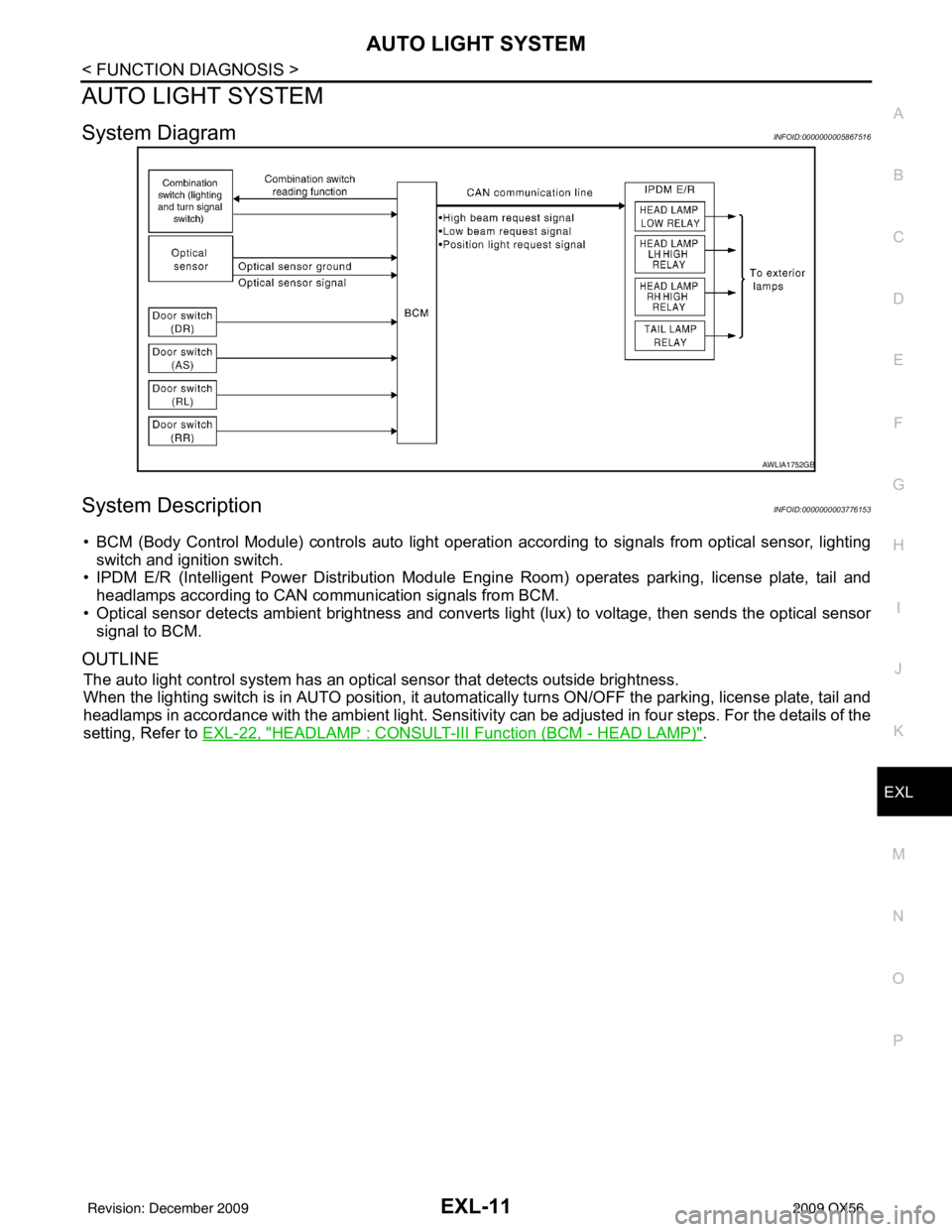
System DiagramINFOID:0000000005867516
System DescriptionINFOID:0000000003776153
• BCM (Body Control Module) controls auto light operati on according to signals from optical sensor, lighting
switch and ignition switch.
• IPDM E/R (Intelligent Power Distribution Module Engine Room) operates parking, license plate, tail and
headlamps according to CAN communication signals from BCM.
• Optical sensor detects ambient br ightness and converts light (lux) to voltage, then sends the optical sensor
signal to BCM.
OUTLINE
The auto light control system has an optical sensor that detects outside brightness.
When the lighting switch is in AUTO position, it automat ically turns ON/OFF the parking, license plate, tail and
headlamps in accordance with the ambient light. Sensitivity can be adjusted in four steps. For the details of the
setting, Refer to EXL-22, "
HEADLAMP : CONSULT-III F unction (BCM - HEAD LAMP)".
AWLIA1752GB
Revision: December 20092009 QX56
Page 1962 of 4171
EXL-14
< FUNCTION DIAGNOSIS >
FRONT FOG LAMP
FRONT FOG LAMP
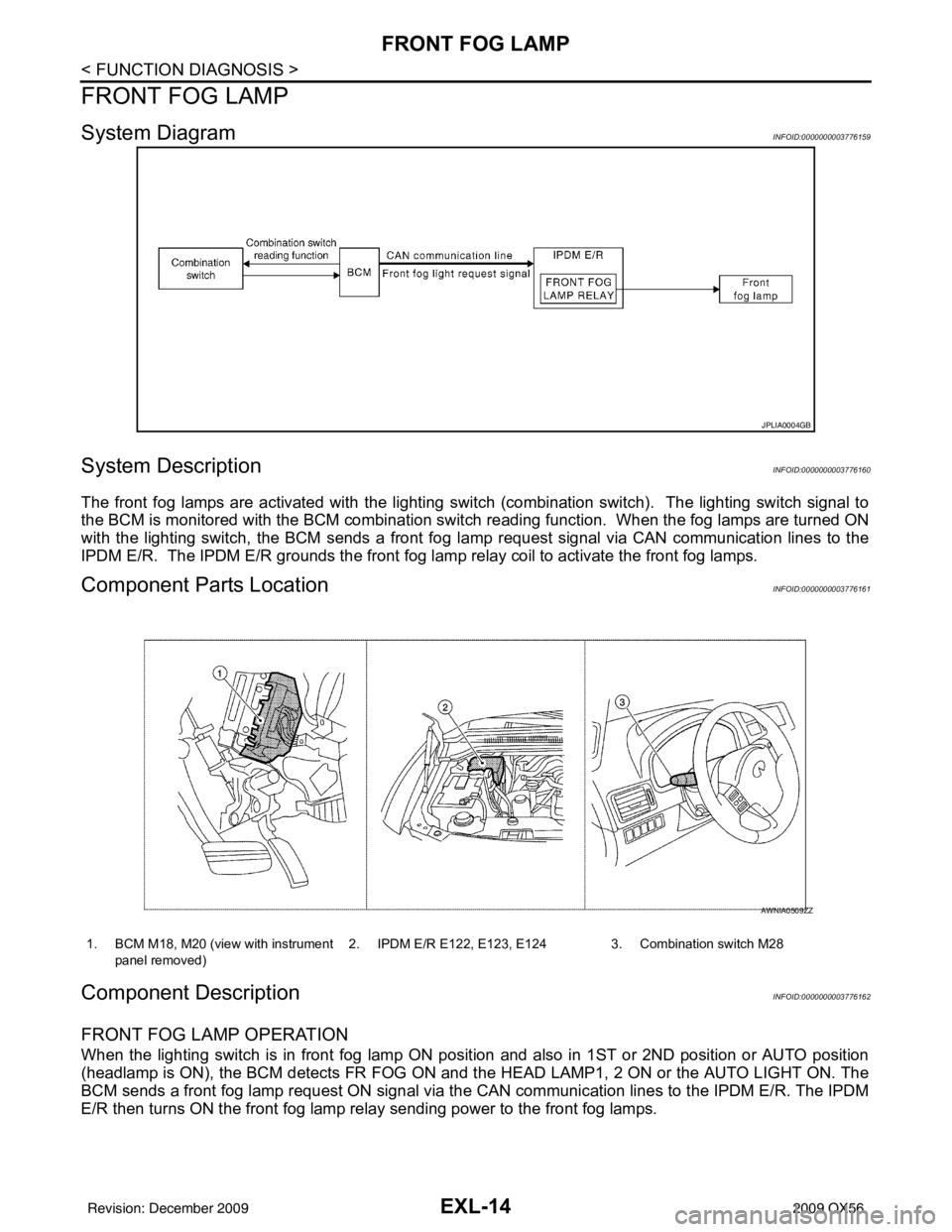
System DiagramINFOID:0000000003776159
System DescriptionINFOID:0000000003776160
The front fog lamps are activated with the lighting switch (combination switch). The lighting switch signal to
the BCM is monitored with the BCM combination swit ch reading function. When the fog lamps are turned ON
with the lighting switch, the BCM sends a front fog la mp request signal via CAN communication lines to the
IPDM E/R. The IPDM E/R grounds the front fog la mp relay coil to activate the front fog lamps.
Component Parts LocationINFOID:0000000003776161
Component DescriptionINFOID:0000000003776162
FRONT FOG LAMP OPERATION
When the lighting switch is in front fog lamp ON posit ion and also in 1ST or 2ND position or AUTO position
(headlamp is ON), the BCM detects FR FOG ON and the HEAD LAMP1, 2 ON or the AUTO LIGHT ON. The
BCM sends a front fog lamp request ON signal via the CAN communication lines to the IPDM E/R. The IPDM
E/R then turns ON the front fog lamp relay sending power to the front fog lamps.
JPLIA0004GB
1. BCM M18, M20 (view with instrument
panel removed) 2. IPDM E/R E122, E123, E124 3. Combination switch M28
AWNIA0509ZZ
Revision: December 20092009 QX56
Page 1963 of 4171
TURN SIGNAL AND HAZARD WARNING LAMPSEXL-15
< FUNCTION DIAGNOSIS >
C
DE
F
G H
I
J
K
M A
B
EXL
N
O P
TURN SIGNAL AND HA ZARD WARNING LAMPS
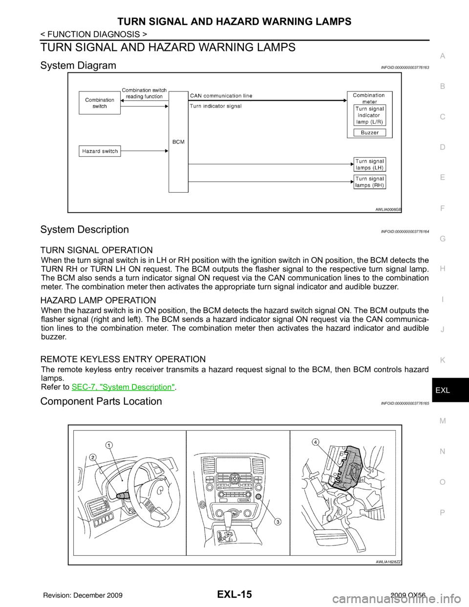
System DiagramINFOID:0000000003776163
System DescriptionINFOID:0000000003776164
TURN SIGNAL OPERATION
When the turn signal switch is in LH or RH position with the ignition switch in ON position, the BCM detects the
TURN RH or TURN LH ON request. The BCM outputs the fl asher signal to the respective turn signal lamp.
The BCM also sends a turn indicator signal ON reques t via the CAN communication lines to the combination
meter. The combination meter then activates the appropriate turn signal indicator and audible buzzer.
HAZARD LAMP OPERATION
When the hazard switch is in ON position, the BCM detects the hazard switch signal ON. The BCM outputs the
flasher signal (right and left). The BCM sends a hazar d indicator signal ON request via the CAN communica-
tion lines to the combination meter. The combinati on meter then activates the hazard indicator and audible
buzzer.
REMOTE KEYLESS ENTRY OPERATION
The remote keyless entry receiver transmits a hazard request signal to the BCM, then BCM controls hazard
lamps.
Refer to SEC-7, "
System Description".
Component Parts LocationINFOID:0000000003776165
AWLIA0006GB
AWLIA1628ZZ
Revision: December 20092009 QX56
Page 1964 of 4171
EXL-16
< FUNCTION DIAGNOSIS >
TURN SIGNAL AND HAZARD WARNING LAMPS
Component Description
INFOID:0000000003776166
1. Combination meter M23, M24 2. Combination switch M28 3. Hazard switch M55
4. BCM M18, M20 (view with instrument panel removed)
Part name Description
BCM Controls turn signal and hazard flasher operation.
Combination switch Lighting and turn signal switch requests are output to the BCM.
Hazard switch Hazard flasher request signal is output to the BCM.
Combination meter Outputs turn and hazard indicator as requested by the BCM.
Revision: December 20092009 QX56
Page 1967 of 4171
TRAILER TOWEXL-19
< FUNCTION DIAGNOSIS >
C
DE
F
G H
I
J
K
M A
B
EXL
N
O P
TRAILER TOW
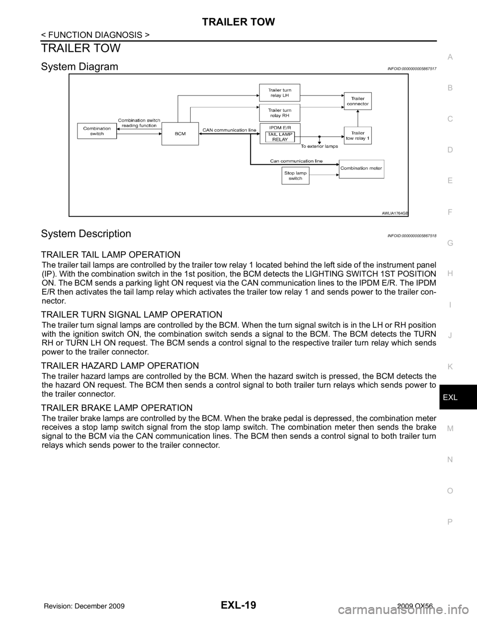
System DiagramINFOID:0000000005867517
System DescriptionINFOID:0000000005867518
TRAILER TAIL LAMP OPERATION
The trailer tail lamps are controlled by the trailer tow re lay 1 located behind the left side of the instrument panel
(IP). With the combination switch in the 1st position, the BCM detects the LI GHTING SWITCH 1ST POSITION
ON. The BCM sends a parking light ON request via the CAN communication lines to the IPDM E/R. The IPDM
E/R then activates the tail lamp relay which activates t he trailer tow relay 1 and sends power to the trailer con-
nector.
TRAILER TURN SIGNAL LAMP OPERATION
The trailer turn signal lamps are controlled by the BCM. When the turn signal switch is in the LH or RH position
with the ignition switch ON, the combination switch sends a signal to the BCM. The BCM detects the TURN
RH or TURN LH ON request. The BCM sends a control signal to the respective trailer turn relay which sends
power to the trailer connector.
TRAILER HAZARD LAMP OPERATION
The trailer hazard lamps are controlled by the BCM. When the hazard switch is pressed, the BCM detects the
the hazard ON request. The BCM then sends a control signal to both trailer turn relays which sends power to
the trailer connector.
TRAILER BRAKE LAMP OPERATION
The trailer brake lamps are controlled by the BCM. W hen the brake pedal is depressed, the combination meter
receives a stop lamp switch signal from the stop lamp switch. The combination meter then sends the brake
signal to the BCM via the CAN communication lines. The BCM then sends a control signal to both trailer turn
relays which sends power to the trailer connector.
AWLIA1764GB
Revision: December 20092009 QX56
Page 1968 of 4171
EXL-20
< FUNCTION DIAGNOSIS >
TRAILER TOW
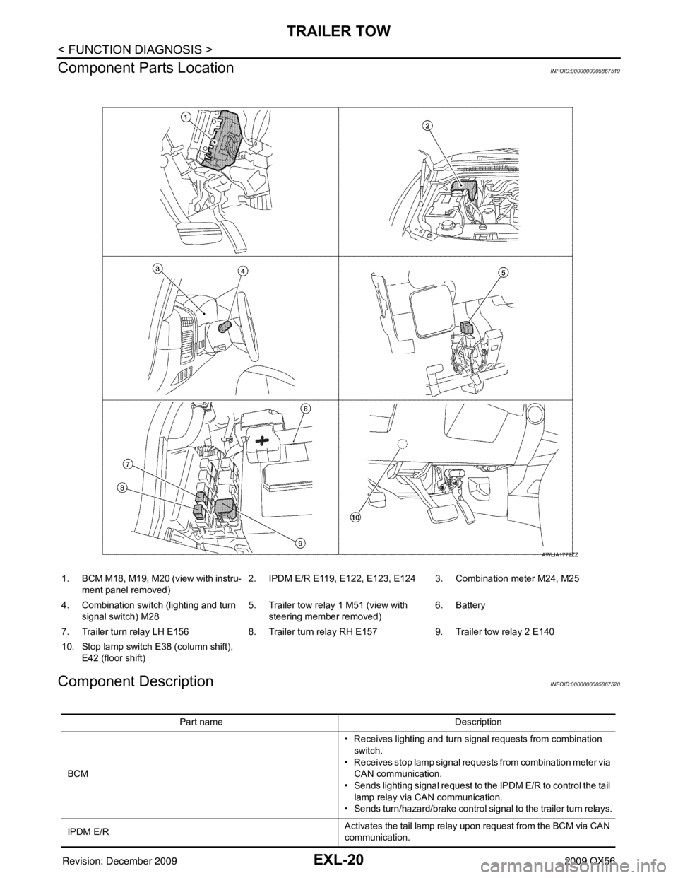
Component Parts Location
INFOID:0000000005867519
Component DescriptionINFOID:0000000005867520
1. BCM M18, M19, M20 (view with instru- ment panel removed) 2. IPDM E/R E119, E122, E123, E124 3. Combination meter M24, M25
4. Combination switch (lighting and turn signal switch) M28 5. Trailer tow relay 1 M51 (view with
steering member removed) 6. Battery
7. Trailer turn relay LH E156 8. Trailer turn relay RH E157 9. Trailer tow relay 2 E140
10. Stop lamp switch E38 (column shift), E42 (floor shift)
AWLIA1772ZZ
Part name Description
BCM • Receives lighting and turn signal requests from combination
switch.
• Receives stop lamp signal requests from combination meter via CAN communication.
• Sends lighting signal request to the IPDM E/R to control the tail lamp relay via CAN communication.
• Sends turn/hazard/brake control signal to the trailer turn relays.
IPDM E/R Activates the tail lamp relay upon request from the BCM via CAN
communication.
Revision: December 20092009 QX56
Page 1969 of 4171
TRAILER TOWEXL-21
< FUNCTION DIAGNOSIS >
C
DE
F
G H
I
J
K
M A
B
EXL
N
O P
Combination meter • Receives stop lamp switch signal from stop lamp switch.
• Sends stop lamp signal request to the BCM via CAN communi-
cation.
Combination switch (lighting and turn signal switch) Outputs lighting and turn signal requests to the BCM.
Revision: December 20092009 QX56
Page 1970 of 4171

EXL-22
< FUNCTION DIAGNOSIS >
DIAGNOSIS SYSTEM (BCM)
DIAGNOSIS SYSTEM (BCM)
HEADLAMP
HEADLAMP : CONSULT-III Function (BCM - HEAD LAMP)INFOID:0000000004215497
WORK SUPPORT
*: Initial setting
DATA MONITOR
ACTIVE TEST
Work Item Setting itemSetting
BATTERY SAVER SET ON* With the exterior lamp battery saver function
OFF Without the exterior lamp battery saver function
CUSTOM A/LIGHT SET-
TING MODE1* Normal
MODE2 More sensitive setting than normal setting (Turns ON earlier than normal operation.)
MODE3 More sensitive setting than MODE 2 (Turns ON earlier than MODE 2.)
MODE4 Less sensitive setting than normal setting (Turns ON later than normal operation.)
ILL DELAY SET MODE1* 45 sec.
Sets delay timer function timer operation time
(All doors closed)
MODE2
Without the func-
tion
MODE3 30 sec.
MODE4 60 sec.
MODE5 90 sec.
MODE6 120 sec.
MODE7 150 sec.
MODE8 180 sec.
Monitor Item [Unit] Description
IGN ON SW [ON/OFF] Ignition switch (ON) status judged from IGN signal (ignition power supply)
HI BEAM SW [ON/OFF]
Each switch status that BCM judges from the combination switch reading function
H/L SW POS [ON/OFF]
LIGHT SW 1ST [ON/OFF]
PASSING SW [ON/OFF]
AUTO LIGHT SW [ON/OFF]
FR FOG SW [ON/OFF]
DOOR SW-DR [ON/OFF]
The switch status input from front door switch LH
AUT LIGHT SYS [ON/OFF] Auto light system status that BCM judges from the vehicle condition
Test ItemOperation Description
TA I L L A M P ON
Transmits the position light reques
t signal to IPDM E/R with CAN com-
munication to turn the tail lamp ON.
OFF Stops the tail lamp request signal transmission.
HEAD LAMP HI
Transmits the high beam request signal with CAN communication to turn
the headlamp (HI).
LO Transmits the low beam request signal with CAN communication to turn
the headlamp (LO).
OFF Stops the high & low beam request signal transmission.
Revision: December 20092009 QX56