2009 INFINITI QX56 turn signal
[x] Cancel search: turn signalPage 1803 of 4171
![INFINITI QX56 2009 Factory Service Manual
EC-476
< SYMPTOM DIAGNOSIS >[VK56DE]
ENGINE CONTROL SYSTEM SYMPTOMS
1 - 6: The numbers refer to the order of inspection.
(continued on next page)
SYSTEM — ENGINE MECHANICAL & OTHER
Mass air flow se INFINITI QX56 2009 Factory Service Manual
EC-476
< SYMPTOM DIAGNOSIS >[VK56DE]
ENGINE CONTROL SYSTEM SYMPTOMS
1 - 6: The numbers refer to the order of inspection.
(continued on next page)
SYSTEM — ENGINE MECHANICAL & OTHER
Mass air flow se](/manual-img/42/57031/w960_57031-1802.png)
EC-476
< SYMPTOM DIAGNOSIS >[VK56DE]
ENGINE CONTROL SYSTEM SYMPTOMS
1 - 6: The numbers refer to the order of inspection.
(continued on next page)
SYSTEM — ENGINE MECHANICAL & OTHER
Mass air flow sensor circuit
1
12 2
222 2 EC-103,
EC-109
Engine coolant temperature sensor circuit
333
EC-120,
EC-128
Air fuel ratio (A/F ) sensor 1 circuit EC-136
,
EC-140
,
EC-143
,
EC-146
,
EC-377
Throttle position sensor circuit 22EC-124
,
EC-185
,
EC-302
,
EC-304
,
EC-369
Accelerator pedal position sensor circuit 3 2 1 EC-280
,
EC-362
,
EC-365
,
EC-373
Knock sensor circuit 2 3 EC-195
Crankshaft position sensor (POS) circuit 2 2EC-198
Camshaft position sensor (PHASE) circuit 3 2 EC-202
Vehicle speed signal circuit 2 3 3 3 EC-271
Power steering pressure sensor circuit 2 3 3 EC-277
ECM 22333333333 EC-280,
EC-282
Intake valve timing control solenoid valve cir-
cuit 32 13223 3
EC-100
Transmission range signal circuit 3 3 3 3 3 EC-288
Refrigerant pressure sensor circuit 2 3 3 4EC-416
Electrical load signal circuit 3EC-390
Air conditioner circuit 223333333 3 2HAC-25
ABS actuator and electric unit (control unit) 4 BRC-37
SYMPTOM
Refer-
ence page
HARD/NO START/RESTART (EXCP. HA)
ENGINE STALL
HESITATION/SURGING/FLAT SPOT
SPARK KNOCK/DETONATION
LACK OF POWER/POOR ACCELERATION
HIGH IDLE/LOW IDLE
ROUGH IDLE/HUNTING
IDLING VIBRATION
SLOW/NO RETURN TO IDLE
OVERHEATS/WATER TEMPERATURE HIGH
EXCESSIVE FUEL CONSUMPTION
EXCESSIVE OIL CONSUMPTION
BATTERY DEAD (UNDER CHARGE)
Warranty symptom code AA AB AC AD AE AF AG AH AJ AK AL AM HA
Revision: December 20092009 QX56
Page 1804 of 4171
![INFINITI QX56 2009 Factory Service Manual
ENGINE CONTROL SYSTEM SYMPTOMSEC-477
< SYMPTOM DIAGNOSIS > [VK56DE]
C
D
E
F
G H
I
J
K L
M A
EC
NP
O
SYMPTOM
Reference
page
HARD/NO START/RESTART (EXCP. HA)
ENGINE STALL
HESITATION/SURGING/FLAT SPOT
INFINITI QX56 2009 Factory Service Manual
ENGINE CONTROL SYSTEM SYMPTOMSEC-477
< SYMPTOM DIAGNOSIS > [VK56DE]
C
D
E
F
G H
I
J
K L
M A
EC
NP
O
SYMPTOM
Reference
page
HARD/NO START/RESTART (EXCP. HA)
ENGINE STALL
HESITATION/SURGING/FLAT SPOT](/manual-img/42/57031/w960_57031-1803.png)
ENGINE CONTROL SYSTEM SYMPTOMSEC-477
< SYMPTOM DIAGNOSIS > [VK56DE]
C
D
E
F
G H
I
J
K L
M A
EC
NP
O
SYMPTOM
Reference
page
HARD/NO START/RESTART (EXCP. HA)
ENGINE STALL
HESITATION/SURGING/FLAT SPOT
SPARK KNOCK/DETONATION
LACK OF POWER/POOR ACCELERATION
HIGH IDLE/LOW IDLE
ROUGH IDLE/HUNTING
IDLING VIBRATION
SLOW/NO RETURN TO IDLE
OVERHEATS/WATER TEMPERATURE HIGH
EXCESSIVE FUEL CONSUMPTION
EXCESSIVE OIL CONSUMPTION
BATTERY DEAD (UNDER CHARGE)
Warranty symptom code AA AB AC AD AE AF AG AH AJ AK AL AM HA
Fuel Fuel tank 5
5 FL-11
Fuel piping 5 5 5 5 5 5
FL-6
Va p o r l o c k —
Valve deposit 5 555 55 5 —
Poor fuel (Heavy weight gasoline,
Low octane) —
Air Air duct
55555 5 EM-25
Air cleaner
EM-25
Air leakage from air duct
(Mass air flow sensor — electric
throttle control actuator)
5555 EM-25
Electric throttle control actuator
EM-26
Air leakage from intake manifold/
Collector/GasketEM-26
Cranking Battery
111111
11
PG-77
Generator circuit
CHG-6
Starter circuit 3STR-8
Signal plate 6EM-45
Transmission range signal 4TM-44
Engine Cylinder head
55555 55 5 EM-68
Cylinder head gasket 4 3
Cylinder block
66666 66 6 4
EM-83
Piston
Piston ring
Connecting rod
Bearing
Crankshaft
Va l v e
mecha-
nism Timing chain
55555 55 5 EM-45
Camshaft
EM-53
Intake valve timing controlEM-53
Intake valve
3EM-68
Exhaust valve
Revision: December 20092009 QX56
Page 1903 of 4171

EM-80
< REMOVAL AND INSTALLATION >
ENGINE ASSEMBLY
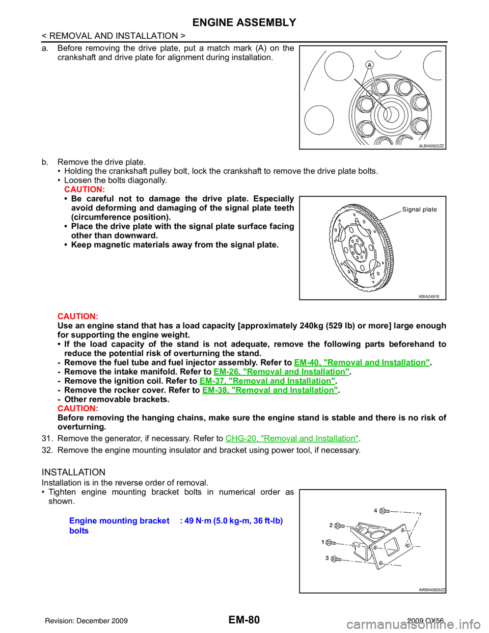
a. Before removing the drive plate, put a match mark (A) on thecrankshaft and drive plate for alignment during installation.
b. Remove the drive plate. • Holding the crankshaft pulley bolt, lock the crankshaft to remove the drive plate bolts.
• Loosen the bolts diagonally.
CAUTION:
• Be careful not to damage the drive plate. Especiallyavoid deforming and damaging of the signal plate teeth
(circumference position).
• Place the drive plate with th e signal plate surface facing
other than downward.
• Keep magnetic materials away from the signal plate.
CAUTION:
Use an engine stand that has a load capacity [a pproximately 240kg (529 lb) or more] large enough
for supporting the engine weight.
• If the load capacity of the stand is not adeq uate, remove the following parts beforehand to
reduce the potential risk of overturning the stand.
- Remove the fuel tube and fuel injector assembly. Refer to EM-40, "
Removal and Installation".
- Remove the intake manifold. Refer to EM-26, "
Removal and Installation".
- Remove the ignition coil. Refer to EM-37, "
Removal and Installation".
- Remove the rocker cover. Refer to EM-38, "
Removal and Installation".
- Other removable brackets.
CAUTION:
Before removing the hanging chains, make sure th e engine stand is stable and there is no risk of
overturning.
31. Remove the generator, if necessary. Refer to CHG-20, "
Removal and Installation".
32. Remove the engine mounting insulator and bracket using power tool, if necessary.
INSTALLATION
Installation is in the reverse order of removal.
• Tighten engine mounting bracket bolts in numerical order as shown.
ALBIA0522ZZ
KBIA2491E
Engine mounting bracket
bolts : 49 N·m (5.0 kg-m, 36 ft-lb)
AWBIA0820ZZ
Revision: December 20092009 QX56
Page 1949 of 4171

EXL-1
DRIVER CONTROLS
C
DE
F
G H
I
J
K
M
SECTION EXL
A
B
EXL
N
O P
CONTENTS
EXTERIOR LIGHTING SYSTEM
BASIC INSPECTION ....... .............................4
DIAGNOSIS AND REPAIR WORKFLOW ..... .....4
Work Flow ........................................................... ......4
FUNCTION DIAGNOSIS ...............................7
HEADLAMP .................................................... .....7
System Diagram .................................................. ......7
System Description ...................................................7
Component Parts Location ........................................7
Component Description .............................................7
DAYTIME LIGHT SYSTEM .................................9
System Diagram .................................................. ......9
System Description ...................................................9
Component Parts Location ........................................9
Component Description ...........................................10
AUTO LIGHT SYSTEM ......................................11
System Diagram ......................................................11
System Description .................................................11
Component Parts Location ......................................12
Component Description ...........................................12
HEADLAMP AIMING SYSTEM (MANUAL) .......13
System Diagram .................................................. ....13
System Description .................................................13
Component Parts Location ......................................13
Component Description ...........................................13
FRONT FOG LAMP ............................................14
System Diagram .................................................. ....14
System Description .................................................14
Component Parts Location ......................................14
Component Description ...........................................14
TURN SIGNAL AND HAZARD WARNING
LAMPS ...............................................................
15
System Diagram .................................................. ....15
System Description .................................................15
Component Parts Location ......................................15
Component Description ....................................... ....16
PARKING, LICENSE PLATE AND TAIL
LAMPS ..............................................................
17
System Diagram ......................................................17
System Description ..................................................17
Component Parts Location ......................................17
Component Description ...........................................18
TRAILER TOW ..................................................19
System Diagram ......................................................19
System Description ..................................................19
Component Parts Location ......................................20
Component Description ...........................................20
DIAGNOSIS SYSTEM (BCM) ...........................22
HEADLAMP ........................................................... ....22
HEADLAMP : CONSULT-III Function (BCM -
HEAD LAMP) ...........................................................
22
FLASHER ............................................................... ....23
FLASHER : CONSULT-III Function (BCM -
FLASHER) ...............................................................
23
COMB SW .............................................................. ....23
COMB SW : CONSULT-III Function (BCM -
COMB SW) ..............................................................
23
DIAGNOSIS SYSTEM (IPDM E/R) ...................25
Diagnosis Description ..............................................25
CONSULT - III Function (IPDM E/R) .......................27
COMPONENT DIAGNOSIS .........................30
POWER SUPPLY AND GROUND CIRCUIT ....30
BCM (BODY CONTROL MODULE) ...................... ....30
BCM (BODY CONTROL MODULE) : Diagnosis
Procedure ............................................................ ....
30
IPDM E/R (INTELLIGENT POWER DISTRIBU-
TION MODULE ENGINE ROOM) .......................... ....
31
Revision: December 20092009 QX56
Page 1950 of 4171

EXL-2
IPDM E/R (INTELLIGENT POWER DISTRIBU-
TION MODULE ENGINE ROOM) : Diagnosis Pro-
cedure .....................................................................
31
HEADLAMP (HI) CIRCUIT ................................32
Description ........................................................... ...32
Component Function Check ...................................32
Diagnosis Procedure - Without Daytime Light Sys-
tem ..........................................................................
32
Diagnosis Procedure - With Daytime Light System
...
33
HEADLAMP (LO) CIRCUIT ...............................35
Description ........................................................... ...35
Component Function Check ...................................35
Diagnosis Procedure - Without Daytime Light Sys-
tem ..........................................................................
35
Diagnosis Procedure - With Daytime Light System
...
36
FRONT FOG LAMP CIRCUIT ...........................38
Description ........................................................... ...38
Component Function Check ...................................38
Diagnosis Procedure ..............................................38
PARKING LAMP CIRCUIT ................................40
Description ........................................................... ...40
Component Function Check ...................................40
Diagnosis Procedure - Without Daytime Light Sys-
tem ..........................................................................
40
Diagnosis Procedure - With Daytime Light System
...
42
TURN SIGNAL LAMP CIRCUIT ........................46
Description ........................................................... ...46
Component Function Check ...................................46
Diagnosis Procedure ..............................................46
OPTICAL SENSOR ...........................................49
Description ..............................................................49
Component Function Check ...................................49
Diagnosis Procedure ..............................................49
HEADLAMP AIMING SWITCH ..........................51
Description ........................................................... ...51
Diagnosis Procedure - Without Daytime Light Sys-
tem ..........................................................................
51
Diagnosis Procedure - With Daytime Light System
...
52
HEADLAMP .......................................................53
Wiring Diagram .................................................... ...53
DAYTIME LIGHT SYSTEM ................................57
Wiring Diagram .................................................... ...57
AUTO LIGHT SYSTEM ......................................64
Wiring Diagram .................................................... ...64
HEADLAMP AIMING SYSTEM (MANUAL) ......71
Wiring Diagram .................................................... ...71
FRONT FOG LAMP SYSTEM ...........................75
Wiring Diagram .................................................... ...75
TURN SIGNAL AND HAZARD WARNING
LAMP SYSTEM .............................................. ...
78
Wiring Diagram .................................................... ...78
PARKING, LICENSE PLATE AND TAIL
LAMPS SYSTEM ...............................................
85
Wiring Diagram .................................................... ...85
STOP LAMP ......................................................91
Wiring Diagram .................................................... ...91
BACK-UP LAMP ............................................ ...95
Wiring Diagram .................................................... ...95
TRAILER TOW .................................................100
Wiring Diagram .....................................................100
ECU DIAGNOSIS ......................................106
BCM (BODY CONTROL MODULE) ............... ..106
Reference Value .................................................. .106
Terminal Layout ....................................................108
Physical Values .....................................................108
Wiring Diagram .....................................................114
Fail Safe ...............................................................118
DTC Inspection Priority Chart .............................119
DTC Index ............................................................119
IPDM E/R (INTELLIGENT POWER DISTRI-
BUTION MODULE ENGINE ROOM) ................
121
Reference Value .................................................. .121
Terminal Layout ....................................................123
Physical Values .....................................................123
Wiring Diagram .....................................................128
Fail Safe ...............................................................131
DTC Index ............................................................133
SYMPTOM DIAGNOSIS ...........................134
EXTERIOR LIGHTING SYSTEM SYMPTOMS ..134
Symptom Table .................................................... .134
NORMAL OPERATING CONDITION ...............136
Description ........................................................... .136
BOTH SIDE HEADLAMPS DO NOT SWITCH
TO HIGH BEAM ................................................
137
Description ........................................................... .137
Diagnosis Procedure .............................................137
BOTH SIDE HEADLAMPS (LO) ARE NOT
TURNED ON .....................................................
138
Description ............................................................138
Diagnosis Procedure .............................................138
PARKING, LICENSE PLATE AND TAIL
LAMPS ARE NOT TURNED ON ......................
139
Description ........................................................... .139
Revision: December 20092009 QX56
Page 1951 of 4171

EXL-3
C
DE
F
G H
I
J
K
M A
B
EXL
N
O P
Diagnosis Procedure ...........................................
..
139
BOTH SIDE FRONT FOG LAMPS ARE NOT
TURNED ON .....................................................
140
Description ............................................................140
Diagnosis Procedure .............................................140
PRECAUTION ............................................141
PRECAUTIONS .............................................. ..141
Precaution for Supplemental Restraint System
(SRS) "AIR BAG" and "SEAT BELT PRE-TEN-
SIONER" ............................................................. ..
141
Precaution Necessary for Steering Wheel Rota-
tion After Battery Disconnect ............................... ..
141
General precautions for service operations ..........142
ON-VEHICLE REPAIR .... ...........................143
ADJUSTMENT AND INSPECTION ................ ..143
HEADLAMP ........................................................... ..143
HEADLAMP : Aiming Adjustment .........................143
FRONT FOG LAMP ............................................... ..144
FRONT FOG LAMP : Aiming Adjustment .............144
REMOVAL AND INSTALLATION .............146
HEADLAMP .................................................... ..146
Bulb Replacement .................................................146
Removal and Installation .......................................147
Disassembly and Assembly ................................ ..147
AUTO LIGHT SYSTEM ....................................149
Removal and Installation ..................................... ..149
FRONT FOG LAMP ........................................150
Bulb Replacement .................................................150
Removal and Installation .......................................150
LIGHTING & TURN SIGNAL SWITCH ...........152
Removal and Installation .......................................152
HAZARD SWITCH ..........................................153
Removal and Installation .......................................153
PUDDLE LAMP ...............................................154
Removal and Installation .......................................154
Bulb Replacement .................................................154
LICENSE PLATE LAMP .................................155
Bulb Replacement .................................................155
Removal and Installation .......................................155
STOP LAMP ....................................................156
Bulb Replacement .................................................156
Removal and Installation .......................................156
REAR COMBINATION LAMP .........................157
Bulb Replacement .................................................157
Removal and Installation .......................................157
SERVICE DATA AND SPECIFICATIONS
(SDS) ............... .......................................... .
158
BULB SPECIFICATIONS ................................158
Headlamp ............................................................ ..158
Exterior Lamp ........................................................158
Revision: December 20092009 QX56
Page 1955 of 4171

HEADLAMPEXL-7
< FUNCTION DIAGNOSIS >
C
DE
F
G H
I
J
K
M A
B
EXL
N
O P
FUNCTION DIAGNOSIS
HEADLAMP
System DiagramINFOID:0000000005867511
System DescriptionINFOID:0000000005867512
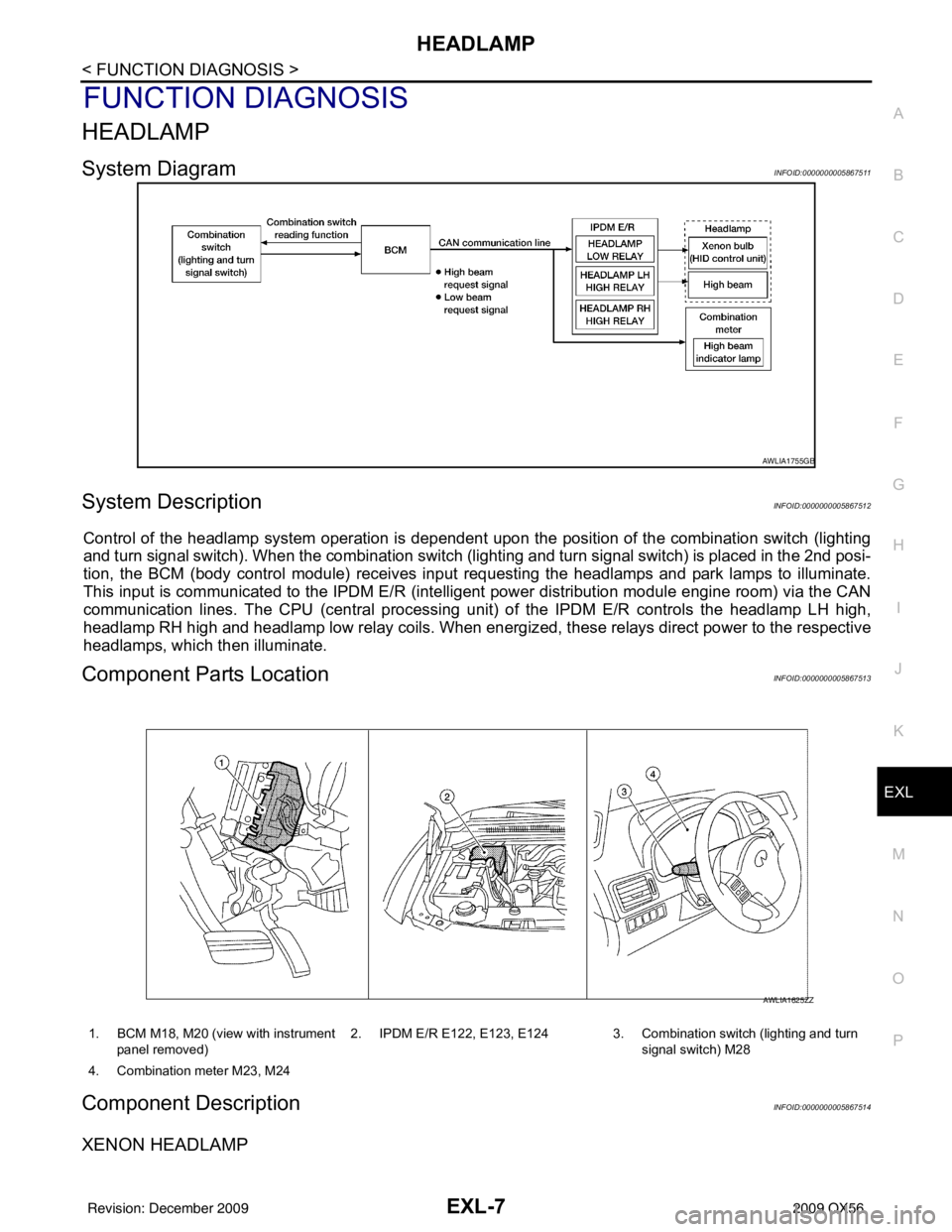
Control of the headlamp system operation is dependent upon t he position of the combination switch (lighting
and turn signal switch). When the combination switch (lighting and turn signal switch) is placed in the 2nd posi-
tion, the BCM (body control module) receives input requesting the headlamps and park lamps to illuminate.
This input is communicated to the IPDM E/R (intelligent power distribution module engine room) via the CAN
communication lines. The CPU (central processing unit) of the IPDM E/R controls the headlamp LH high,
headlamp RH high and headlamp low relay coils. When energiz ed, these relays direct power to the respective
headlamps, which then illuminate.
Component Parts LocationINFOID:0000000005867513
Component DescriptionINFOID:0000000005867514
XENON HEADLAMP
AWLIA1755GB
1. BCM M18, M20 (view with instrument
panel removed) 2. IPDM E/R E122, E123, E124 3. Combination switch (lighting and turn
signal switch) M28
4. Combination meter M23, M24
AWLIA1625ZZ
Revision: December 20092009 QX56
Page 1956 of 4171

EXL-8
< FUNCTION DIAGNOSIS >
HEADLAMP
A Xenon type headlamp is adapted to the low beam headlamps. Xenon bulbs do not use a filament. Instead,
they produce light when a high voltage current is pa ssed between two tungsten electrodes through a mixture
of Xenon (an inert gas) and certain other metal halides. In addition to added lighting power, electronic control
of the power supply gives the headlamps stable quality and tone color. Following are some of the advantages
of the Xenon type headlamp.
• The light produced by the headlamps is a white color comparable to sunlight that is easy on the eyes.
• Light output is nearly double that of halogen headlamps, affording increased area of illumination.
• The light features a high relative spectral distribution at wavelengths to which the human eye is most sensi- tive. This means that even in the rain, more light is reflected back from the road surface toward the vehicle,
for added visibility.
• Power consumption is approximately 25 percent less than halogen headlamps, reducing battery load.
HIGH BEAM OPERATION/FLASH-TO-PASS OPERATION
With the combination switch (lighting and turn signal switch) in the 2ND position and placed in HIGH position,
the BCM receives input requesting the headlamp high beams to illuminate. The flash to pass feature can be
used any time and also sends a signal to the BCM. This input is communicated to the IPDM E/R via the CAN
communication lines. The CPU of the combination meter c ontrols the ON/OFF status off the HIGH BEAM indi-
cator. The CPU of the IPDM E/R controls the headlamp LH high and RH high relay coils which supplies power
to the high beam headlamps.
The combination meter receives a high beam request signal (ON) via the CAN communication lines and turns
the high beam indicator lamp ON.
Revision: December 20092009 QX56